Williams CARMEL AC2030TNA User manual

WARNING: If the information in these instructions
is not followed exactly, a fire or explosion may result
causing property damage, personal injury or loss of life.
-Do not store or use gasoline or other flammable vapors
and liquids in the vicinity of this or any other appliance.
WHAT TO DO IF YOU SMELL GAS:
•Open all windows.
•Do not try to light any appliance.
•Do not touch any electrical switch; do not use
any phone or cell phone in your building.
•Extinguish any open flame.
•Immediately call your gas supplier from a neighbor’s
phone. Follow the gas supplier’s instructions.
•If you cannot reach the gas supplier, call the fire
department.
–Installation and service must be performed by a
qualified installer, service agency or the gas supplier.
20,000 - 30,000
BTU/hr.
CARMEL
TM AC2030TNA
TOP VENT GAS WALL HEATER
WARNING: INSTALLATION IN MANUFACTURED
HOMES Williams Top-Vent Furnaces are allowed in
manufactured homes when the following conditions are met:
-The manufactured home is permanently sited per local codes.
-The manufactured home is manufactured after
6/15/1976 and is HUD approved with a red certification
label (US only). These models are allowed only in
the USA. This applies to aftermarket manufactured
home installations where the home is sold, installed
and permanently sited. Not for
manufactured home
manufacturer (factory) installation. These units may not be
installed in trailers or recreational vehicles.
WARNING: This product can expose you to
chemicals including epichlorohydrin which is known to
the State of California to cause cancer and birth defects
and/or other reproductive harm. For information go to
www.p65warnings.ca.gov
WARNING: Improper installation, adjustment,
alteration, service or maintenance can cause injury or
property damage. Refer to this manual. For assistance or
for additional information consult a qualified installer,
service agency or the gas supplier.
SINGLE SIDED MODEL NUMBER:
AC2030TNA (natural gas)
SAVE THIS MANUAL FOR FUTURE REFERENCE.
READ THIS OWNER’S MANUAL CAREFULLY BEFORE YOU
INSTALL YOUR NEW WILLIAMS WALL FURNACE.
250 West Laurel Street, Colton CA 92324 • WWW.WFC-FC.COM • 1-888-444-1212
OWNER’S MANUAL
INSTALLATION INSTRUCTIONS
VISITEZ NOTRE SITE WEB POUR LA VERSION FRANÇAISE DE CE MANUEL
VISITE NUESTRA PÁGINA WEB PARA LA VERSIÓN EN ESPAÑOL DE ESTE MANUAL
https://www.williamscomfortprod.com/products/furnaces/

2CARMELTM AC2030TNA TOP VENT GAS WALL HEATER
WARRANTY
INSTALLATION RECORD
Model No.. Serial No.
Original Purchaser
Address
City and State Zip
Dealer
Address
City and State Zip
Installation Date Name Signature
(Dealer or authorized representative who certifies that this appliance is installed in accordance with Manufacturer’s instructions and local codes.)
The manufacturer, Williams, warrants this wall furnace or heater to
the original purchaser under the following conditions:
ANY WARRANTY CONSIDERATIONS ARE
CONTINGENT ON INSTALLATION BY A
QUALIFIED INSTALLER (CONTRACTOR).
SELF-INSTALLATION IS PROHIBITED AND
WILL INVALIDATE YOUR WARRANTY.
LIMITED ONE-YEAR WARRANTY
1. Any part thereof which proves to be defective in material or
workmanship within one year from date of original purchase
for use will be replaced at the Manufacturer’s option, FOB to
its factory.
2. No liability is assumed by the Manufacturer for removal or
installation labor costs, nor for freight or delivery charges.
LIMITED EXTENDED WARRANTY
1. In addition to the above limited one year warranty on the
complete unit, any combustion chamber which burns out or
rusts under normal installation, use and service conditions
during a period of nine years following expiration of the
one-year warranty period will be exchanged for a like or
functionally similar part.
2. No liability is assumed by the Manufacturer for removal or
installation labor costs, nor for freight or delivery charges.
LIMITATIONS
1. THIS LIMITED WARRANTY IS THE ONLY WARRANTY MADE BY
THE MANUFACTURER, IMPLIED WARRANTIES OF
MERCHANTABILITY OR FITNESS FOR ANY PARTICULAR
PURPOSE ARE LIMITED TO THE SAME ONE YEAR TERM AS
THE EXPRESS WARRANTY. UNDER NO CIRCUMSTANCES
SHALL THE MANUFACTURER BE LIABLE FOR INCIDENTAL,
CONSEQUENTIAL, SPECIAL OR CONTINGENT DAMAGES OR
EXPENSES ARISING DIRECTLY OR INDIRECTLY FROM ANY
DEFECT IN THE PRODUCT OR ANY COMPONENT OR
FROM THE USE THEREOF. THE REMEDIES SET FORTH
HEREIN ARE THE EXCLUSIVE REMEDIES AVAILABLE TO THE
USER AND ARE IN LIEU OF ALL OTHER REMEDIES.
Some states do not allow limitation on how long an implied
warranty lasts, and some states do not allow the exclusion or
limitation of incidental or consequential damages, so the above
limitations or exclusions may not apply to you.
2.
This warranty does not include any charge for labor or installation.
3. This warranty does not extend to painted surfaces or to damage
or defects resulting from accident, alteration, misuses or abuse
or improper installation.
4. This warranty does not cover claims which do not involve
defective workmanship or materials.
DUTIES OF THE CONSUMER
1.
The heating equipment must be installed by a qualified installer
and operated in accordance with the installation and
homeowner’s instructions furnished with the equipment.
2. Any travel, diagnostic costs, service labor, and labor to repair
the defective unit will be the responsibility of the owner.
3. A bill of sale, canceled check, payment record or permit should
be kept to verify purchase date to establish the warranty period.
4. Have the installer enter the requested information in the
space below.
GENERAL
1. The manufacturer neither assumes nor authorizes any person
to assume for it any other obligation or liability in connection
with said equipment.
2. Service under this warranty should be obtained by contacting
your dealer. Provide the dealer with the model number, serial
number, and purchase date verification.
3. If, within a reasonable time after contacting your dealer,
satisfactory service has not been received, contact: Customer
Service Department, 250 West Laurel Street, Colton, CA 92324
for assistance.
4. THIS WARRANTY GIVES YOU SPECIFIC LEGAL RIGHTS AND
YOU MAY ALSO HAVE OTHER RIGHTS WHICH VARY FROM
STATE TO STATE.
WARRANTY

CARMELTM AC2030TNA TOP VENT GAS WALL HEATER 3
YOUR WILLIAMS WARRANTY
INSTALLATION RECORD
TABLE OF CONTENTS
SAFETY RULES
INTRODUCTION
BASIC MATERIALS NEEDED
BASIC TOOLS NEEDED
OPTIONAL ACCESSORIES
INSTALLATIONS IN THE STATE OF MASSACHUSETTS
INSTALLING YOUR WALL FURNACE
LOCATING WALL FURNACE AND THERMOSTAT
COMBUSTION & VENTILATION AIR
INSTALLATION
RECESSED MOUNT INSTALLATION
SURFACE MOUNT INSTALLATION
VENT INSTALLATION
ATTACHING YOUR FURNACE
GAS SUPPLY AND PIPING
FRONT PANEL INSTALLATION
THERMOSTAT INSTALLATION
START UP PROCEDURE
OPERATING YOUR FURNACE
HOW TO CARE FOR YOUR FURNACE
INSTALLING YOUR MOTORIZED REAR OUTLET ACCESSORY
MOTORIZED REAR OUTLET REPLACEMENT PARTS
FURNACE EXPLODED VIEW
FURNACE REPLACEMENT PARTS
INSTALLING YOUR POWER SUPPLY KIT
INSTALLING YOUR EXTERNAL POWER SUPPLY KIT
WIRING DIAGRAM
TROUBLESHOOTING
SERVICE HINTS
Quick Reference
Here’s how to:
INSTALLING YOUR FURNACE
Recessed Mount, Surface Mount,
and Vent Installation are
explained starting on page 8.
OPERATING YOUR FURNACE
Igniting your furnace for the first time.
HOW TO CARE FOR YOUR FURNACE
Learn how to keep your new
Williams Furnace operating.
CONTENTS
2
2
3
4
5
6
6
6
6
7
7
8
8
11
13
15
16
17
19
20
21
22
23
24
27
28
29
30
31
32
33
36
8
21
22

4CARMELTM AC2030TNA TOP VENT GAS WALL HEATER
WARNING: Read these rules and the instructions
carefully. Failure to follow these rules and instructions
could cause a malfunction of the furnace. This could
result in death, serious bodily injury and/or property
damage. INSTALLATION MUST CONFORM TO
LOCAL CODES. IN THE ABSENCE OF LOCAL CODES,
INSTALLATION MUST CONFORM TO THE NATIONAL
FUEL GAS CODE, ANSI Z223.1. THE APPLIANCE, WHEN
INSTALLED MUST BE ELECTRICALLY CONNECTED AND
GROUNDED IN ACCORDANCE WITH LOCAL CODES
OR, IN THE ABSENCE OF LOCAL CODES, WITH THE
CURRENT NATIONAL ELECTRICAL CODE ANSI/NFPA
NO. 70.
IN CANADA: Installation must conform to local codes or,
in the absence of local codes, the current CAN/CGA B149
Installation code. The appliance, when installed, must
be grounded in accordance with local codes, with the
current CSA C22.1 Canadian Electrical Code. Reference is
made in this manual regarding gas type as Propane Be
advised that Propane is not available in Canada; refer
to propane.
WARNING: Do not use this furnace if any part has
been under water. Immediately call a qualified service
technician to inspect the furnace and to replace any
part of the control system and any gas control which has
been under water.
1. Use only manufacturer’s replacement parts. Use of any
other parts could cause injury or death.
2. DO NOT install the furnace where it could be isolated by
closing doors to the heated space.
3. DO NOT install these furnaces in a travel trailer,
recreational vehicle or mobile home.
4. MAINTAIN all clearances specified in section “Locating
Wall Furnace and Thermostat” and “Vent Installation.”
5. BE SURE the furnace is for type of gas being used. Check
the nameplate by the gas valve in the lower cabinet.
Do not change it to use other gases without the proper
manufacturer’s gas conversion kit.
6. For natural gas, the minimum inlet gas supply pressure
for the purpose of input adjustment is 5” water column.
The maximum inlet gas supply pressure is 7” water
column.
7. Any safety screen, guard or parts removed for servicing this
appliance must be replaced prior to operating the
appliance to avoid property damage, bodily injury or death.
8. Vent the furnace directly to the outdoors, so that harmful
gases will not collect inside the building. Follow the
venting instructions for your type installation exactly. Use
only the type and size of vent pipe and fittings specified.
9. Provide for adequate combustion and ventilation air. See
page 8-9. The flow of this air to the furnace must not be blocked.
10. NEVER vent flue gases into another room, a fireplace
or any space inside a building. This could cause property
damage, bodily injury or death.
11. NEVER test for gas leaks with an open flame. Use a soap
solution to check all gas connections. This will avoid the
possibility of fire or explosions.
12. ALLOW furnace to cool before servicing. Always shut off
electricity and gas to furnace when working on it. This
will prevent any electrical shocks or burns.
13. DUE TO HIGH TEMPERATURES, locate the furnace out of
traffic and away from furniture and draperies.
14. ALERT children and adults to the hazards of high surface
temperatures and warn them to keep away to avoid
burns or clothing ignition.
15. CAREFULLY supervise young children when they are in
the same room with the furnace.
16. DO NOT place clothing or other flammable material on
or near furnace.
17. INSTALLATION and REPAIR must be done by a qualified
service person. The appliance should be inspected
before use and at least annually by a professional service
person. More frequent cleaning may be required due
to excessive lint from carpeting, bedding material, etc.
It is imperative that control compartments, burners and
circulating air passages be kept clean.
18. BEFORE INSTALLING: To avoid electrical shock, turn off
electrical circuits that pass through the wall where you
are going to install the furnace.
19. BE AWARE of good safety practices by wearing personal
protective equipment such as gloves and safety glasses
to avoid being injured by sharp metal edges in or around
the furnace while cutting or drilling holes in wood and/or
sheet metal.
20. CAUTION: Label all wires prior to disconnection when
servicing controls.
21. DO NOT store or use gasoline or other flammable liquids
or vapors near the furnace.
WARNING: Do not install any of these furnaces in
mobile homes, trailers or recreational vehicles.
SAFETY RULES

CARMELTM AC2030TNA TOP VENT GAS WALL HEATER 5
INTRODUCTION
The following steps are all needed for proper installation
and safe operation of your furnace. If you have any doubts
as to any requirements, check with local authorities. Obtain
professional help where needed. All of the checks and
adjustments in the Start-Up Procedures are vital to the
proper and safe operation of the furnace. Please read the
instructions before you install and use your furnace. This
will help you obtain the full value from this furnace. It could
also help you avoid needless service costs if the answer to
the problem is found within this instruction manual.
Always consult your local heating or plumbing inspector,
building department or gas utility company regarding
regulations codes or ordinances which apply to the
installation of a vented wall furnace.
Check the furnace nameplate, located in the burner
compartment, to make sure your furnace is equipped to
operate on the type of gas available (DO NOT convert the
furnace from natural gas to propane).
Combustion air is drawn in from the room where the
furnace is located and is vented out of the top of the furnace
vertically through vent piping in the stud space to a roof
vent top. Vent material is not supplied with the furnace.
This furnace is equipped with a vent safety shutoff
system designed to protect against improper venting of
combustion products. Operation of this wall furnace when
not connected to a properly installed and maintained
venting system or tampering with the vent safety shutoff
system can result in carbon monoxide (CO) poisoning and
possible death.
The efficiency rating of this furnace is a product thermal
efficiency rating determined under continuous operating
conditions and was determined independent of any
installed system. The furnace will not function unless the
venting system is installed.
1) Seal any unused openings in the venting system.
2) Inspect the venting system for proper size and
horizontal pitch, as required in the National Fuel
Gas Code, ANSI Z223.1/NFPA 54 or the Natural Gas
and Propane Installation Code, CSA B149.1 and
these instructions. Determine that there is no
blockage or restriction, leakage, corrosion and other
deficiencies which could cause an unsafe condition.
3) As far as practical, close all building doors and
windows and all doors between the space in which
the appliance(s) connected to the venting system
are located and other spaces of the building.
4) Close fireplace dampers.
5) Turn on clothes dryers and any appliance not
connected to the venting system. Turn on
any exhaust fans, such as range hoods and
bathroom exhausts, so they are operating at
maximum speed. Do not operate a summer
exhaust fan.
WARNING: CARBON MONOXIDE POISONING HAZARD
Failure to follow the steps outlined below for each appliance connected to the venting system being placed
into operation could result in carbon monoxide poisoning or death.
The following steps shall be followed for each appliance connected to the venting system being placed into
operation, while all other appliances connected to the venting system are not in operation:
6) Follow the lighting instructions. Place the appliance
being inspected into operation. Adjust the thermostat
so appliance is operating continuously.
7) Test for spillage from draft hood equipped appliances
at the draft hood relief opening after 5 minutes
of main burner operation. Use the flame of a match
or candle.
8) If improper venting is observed during any of the
above tests, the venting system must be corrected
in accordance with the National Fuel Gas Code,
ANSI Z223.1/NFPA 54 and/or Natural Gas and Propane
Installation Code, CSA B149.1.
9) After it has been determined that each appliance
connected to the venting system properly vents
when tested as outlined above, return doors, windows,
exhaust fans, fireplace dampers and any other
gas-fired burning appliance to their previous
conditions of use.

6CARMELTM AC2030TNA TOP VENT GAS WALL HEATER
Basic Materials Needed
Pipe and fittings to make gas connections to the furnace.
Vertical venting materials. See page 15, Figure 8.
Pipe Joint Compound resistant to Propane.
Electrical wiring supplies as needed. Minimum wire size is
#14 gauge copper.
Basic Tools Needed
Hand drill or properly grounded electric drill
Expansion bit 1/2” to 1-5/8” or 1/2” and 1-1/2” blade bits
1/8” and 3/16” drill bit (metal)
6 ft. folding rule or tape measure
Screwdriver (medium blade)
Screwdriver (Phillips and Flat Head)
Pliers (wire cutting)
Hammer
Stud Locater or small finishing nails
Tin Snips
8" adjustable wrench
12" adjustable wrench
7/8" wrench
3/4" wrench
1" wrench
Gloves and safety glasses
Helpful Installation Information
The following booklets will help you in making the installation:
ANSI/NFPA 70, or current edition “National Electrical Code”.
In Canada: CSA C22.1 Canadian Electrical Code.
American National Standard Z223.1 or current edition of the
“National Fuel Gas Code.”
Obtain from the American National Standard Institute, Inc.,
1430 Broadway, New York, NY 10018. In Canada, CAN/CGA B149.
Optional Accessories
Free Standing Accessory 4901 (AC2030T Only)
This accessory allows the furnace to be mounted on the
surface of a wall.
Face Panel 4915 -Front Panel
Rear Outlet Registers 6920 (AC2030T Only)
When recessed into a standard 2 x 4 inch interior stud
partition, this accessory directs some of the heated air into the
room opposite the one in which the furnace is installed.
Oval B/W Vent Kit 9929 / 9930 CANADA - This U.L. Listed
B/W vent kit contains four feet of oval, double-walled vent
pipe, plate spacers and base or hold-down plate that starts
the venting from the top of furnace. See Vent Installation on
page 15 for additional items you will need.
Power Supply Kit M119046 - Power adapter for unit.
External Power Supply Kit M119015 - The unit’s standard
power adapter may not be long enough to reach an outlet.
Instead, this external power supply kit can be used to wire
through the wall and into the home’s power supply.
INTRODUCTION
Installations in the state of
Massachusetts
All installations in the State of Massachusetts must use
the following requirements when installing, maintaining
or operating direct-vent propane or natural gas-fired
space heaters.
For direct-vent appliances, mechanical-vent heating
appliances or domestic hot water equipment, where the
bottom of the vent terminal and the air intake is installed
below four feet above grade the following requirements
must be satisfied:
1. If there is not one already present, on each floor level
where there are bedroom(s), a carbon monoxide
detector and alarm shall be placed in the living area
outside the bedroom(s). The carbon monoxide detector
shall comply with NFPA 720 (2005 Edition).
2. A carbon monoxide detector shall be located in the
room that houses the appliance or equipment
and shall:
a. Be powered by the same electrical circuit as the
appliance or equipment such that only one service
switch services both the appliance and the carbon
monoxide detector.
b. Have battery back-up power;
c. Meet ANSI/UL 2034 Standards and comply with NFPA
720 (2005 Edition); and
d. Have been approved and listed by a Nationally
Recognized Testing Laboratory as recognized under
527 CMR.
A CARBON MONOXIDE DETECTOR SHALL:
a. Be located in the room that houses the appliance
or equipment;
b. Be either hard-wired or battery powered or both; and
c. Shall comply with NFPA 720 (2005 Edition).
3. A product-approved vent terminal must be used, and if
applicable, a product-approved air intake must be
used. Installation shall be in strict compliance with the
manufacturer’s instructions. A copy of the installation
instructions shall remain with the appliance or
equipment at the completion of the installation.
4. A metal or plastic identification plate shall be mounted
at the exterior of the building, four feet directly above
the location of vent terminal. The plate shall be of
sufficient size to be easily read from a distance of eight
feet away, and read “Gas Vent Directly Below”.

CARMELTM AC2030TNA TOP VENT GAS WALL HEATER 7
The following steps are needed for proper installation and
safe operation of your furnace. If you have any doubts as to
any requirements, obtain professional help. Remember to
ALWAYS consult your local heating or plumbing inspector,
building department or gas utility company regarding
regulations, codes, or ordinances which apply to the
installation and location of a vented wall furnace.
IMPORTANT
For satisfactory and trouble-free operation, be sure to:
1. Locate the furnace properly within the space to be
heated.
2. Install the furnace in accordance with local codes or
ordinances and instructions provided. In the absence of
local codes or ordinances, install the furnace to conform
with the current edition of the National Fuel Gas Code,
NFPA 54, ANSI Z223.1/Canadian Installation Code, CAN/
CGA B149.
3. Maintain minimum clearances: Floor 2½-inches, ceiling
16- inches, side wall 1-inch.
4. Provide enough combustion and ventilation air.
LOCATING WALL FURNACE & THERMOSTAT
The furnace is installed between 2x4 inch wall studs spaced
on 16-inch centers or a stud space that can be framed in to
16-inches. Consider the following points before attempting
to install the furnace:
CAUTION: Do not make cutouts in the wall or ceiling
before checking in the attic for ceiling joist locations and
proposed venting.
FIGURE 1 MINIMUM SPACING
1. Locate the furnace near the center of the space to be
heated for good air circulation. Do not put it behind a
door or draperies. Do not install the furnace where it
could be isolated by closing doors to the heated space.
Do not locate the furnace where a door could swing over
the front panel or where circulation could be retarded by
furniture or cabinets.
2. Check the minimum spacing needs as shown in Figure 1.
3. The top of the furnace must be at least 16-inches from
the ceiling.
4. When the furnace is properly installed with legs resting
on the floor plate, it sets the dimension from the face
panel to the bare floor. (Approximately 2½-inches
depending on the thickness of floor plate).
5. A protective barrier (metal or wood), cut to match the
width and depth of the furnace, should be used to cover
over any floor coverings such as carpet or vinyl under the
furnace. At no time should the dimension from the
bottom of the face panel to the protective barrier be less
than 1½- inches.
6. In the space to be heated, the side of the furnace may
be as close as 1-inch to an intersecting wall. The recessed
portion may have 0-inches clearance to combustible
material.
7. Select a location that will provide adequate accessibility
clearance for servicing and proper operation.
8. After picking a location, inspect the wall, floor, attic and
roof areas. Make sure there are no pipes, wiring, bracing,
etc., that will interfere with furnace or vent installation. If
required, move them or pick a new installation location.
9. Be sure that gas piping and electrical wiring can be
brought to the location. Electrical wiring is required for
optional blower accessory.
10. If installing the thermostat on the wall, locate the
thermostat approximately 5-feet above the floor on an
inside wall where it will sense the average room
temperature.
The thermostat should be sensing average room
temperature; avoid the following:
HOT SPOTS:
Concealed pipes or ducts
Fireplaces
Registers
TV sets
Radios
Lamps
Direct sunlight
Kitchen
COLD SPOTS:
Concealed pipes or ducts
Stairwell - drafts
Door - drafts
Unheated rooms on
other side of wall
DEAD SPOTS:
Behind doors
Corners and alcoves
7 MIN.
BARE
FLOOR
1 MIN. TO
CLOSET
SIDE WALL
WALL
FURNACE
WALL
APPROX. 2½
CEILING 16 MIN.
INSTALLING YOUR FURNACE

8CARMELTM AC2030TNA TOP VENT GAS WALL HEATER
After picking a location that meets the requirements, check
the walls, attic and roof to make sure there are no obstructions
such as pipes, electrical wiring, etc., which could interfere with
the installation of the furnace or vent pipe. If required, move
them or pick a new location.
WARNING: Danger of property damage, bodily
injury or loss of life. Do not install the furnace in any area
where oxygen is in use.
Combustion & Ventilation Air
When an existing category I heater is removed or replaced,
the original venting system may no longer be sized to
properly vent the attached appliances.
WARNING:
CARBON MONOXIDE POISONING HAZARD
Failure to follow the steps outlined below for each appliance
connected to the venting system being placed into operation
could result in carbon monoxide poisoning or death.
The following steps shall be followed for each appliance
connected to the venting system being placed into operation,
while all other appliances connected to the venting system
are not in operation:
1. Seal any unused openings in the venting system.
2. Inspect the venting system for proper size and horizontal
pitch, as required in the National Fuel Gas Code, ANSI
Z223.1/NFPA 54 or the Natural Gas and Propane
Installation Code, CSA 8149.1 and these instructions.
Determine that there is no blockage or restriction,
leakage, corrosion and other deficiencies which could
cause an unsafe condition.
3. As far as practical, close all building doors and windows
and all doors between the space in which the
appliance(s) connected to the venting system are located
and other spaces of the building.
4. Close fireplace dampers.
5. Turn on clothes dryers and any appliance not connected
to the venting system. Turn on any exhaust fans, such as
range hoods and bathroom exhausts, so they are
operating at maximum speed. Do not operate a summer
exhaust fan.
6. Follow the lighting instructions. Place the appliance
being inspected into operation. Adjust the thermostat
so appliance is operating continuously.
7. Test for spillage from draft hood equipped appliances
at the draft hood relief opening after 5 minutes of main
burner operation. Use the flame of a match or candle.
8. If improper venting is observed during any of the above
tests, the venting system must be corrected in
accordance with the National Fuel Gas Code, ANSI Z223.1/
NFPA 54 and/or Natural Gas and Propane Installation
Code, CSA 8149.1
9. After it has been determined that each appliance
connected to the venting system properly vents when
tested as outlined above, return doors, windows, exhaust
fans, fireplace dampers and any other gashed burning
appliance to their previous conditions of use.
WARNING: Danger of property damage, bodily
injury or loss of life. The furnace and any other fuel-
burning appliances must be provided with enough fresh
air for proper combustion and ventilation of flue gases.
Most homes will require that outside air be supplied into
the heated area.
The high cost of energy for home heating has brought about
new materials and methods used to construct or remodel most
current homes. The improved construction and additional
insulation has reduced the heat loss and made these homes
much tighter around windows and doors so that infiltrated air
is minimal. This creates a problem to supply combustion and
ventilation air for gas-fired or other fuel burning appliances.
Any use of appliances that pull air out of the house (clothes
dryers, exhaust fans, fireplaces, etc.) increases this problem and
appliances could be starving for air.
The combination of a tight energy efficient home with the use
of exhaust fans, fireplaces, clothes dryers, and gas appliances
result in more and more air being drawn from the house until
fresh air may be sucked back into the house down a furnace
flue or fireplace chimney. Carbon monoxide can be the result.
Carbon monoxide (CO) is a colorless, odorless gas produced
when fuel is not burned completely or when the flame does
not receive sufficient oxygen. Automobiles, charcoal, wood fires
and improperly vented or air-starved coal, oil and gas furnaces
or other appliances can produce carbon monoxide.
Do not install furnace in the same room or near a wood solid
fuel burning fireplace.
BE AWARE OF THESE AIRSTARVATION SIGNALS:
1. Headaches, nausea, dizziness.
2. Excessive humidity shown by heavily frosted windows or
a moist “clammy” sensation.
3. Fireplace smoke fills the room or will not draw.
4. Furnace flue backs up.
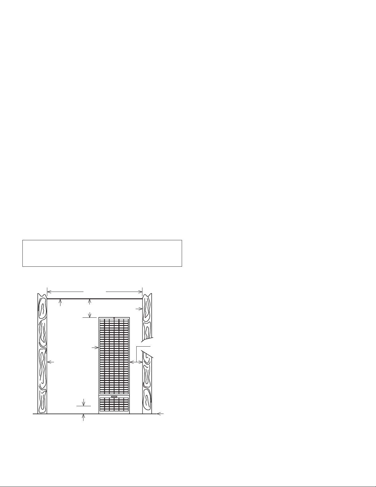
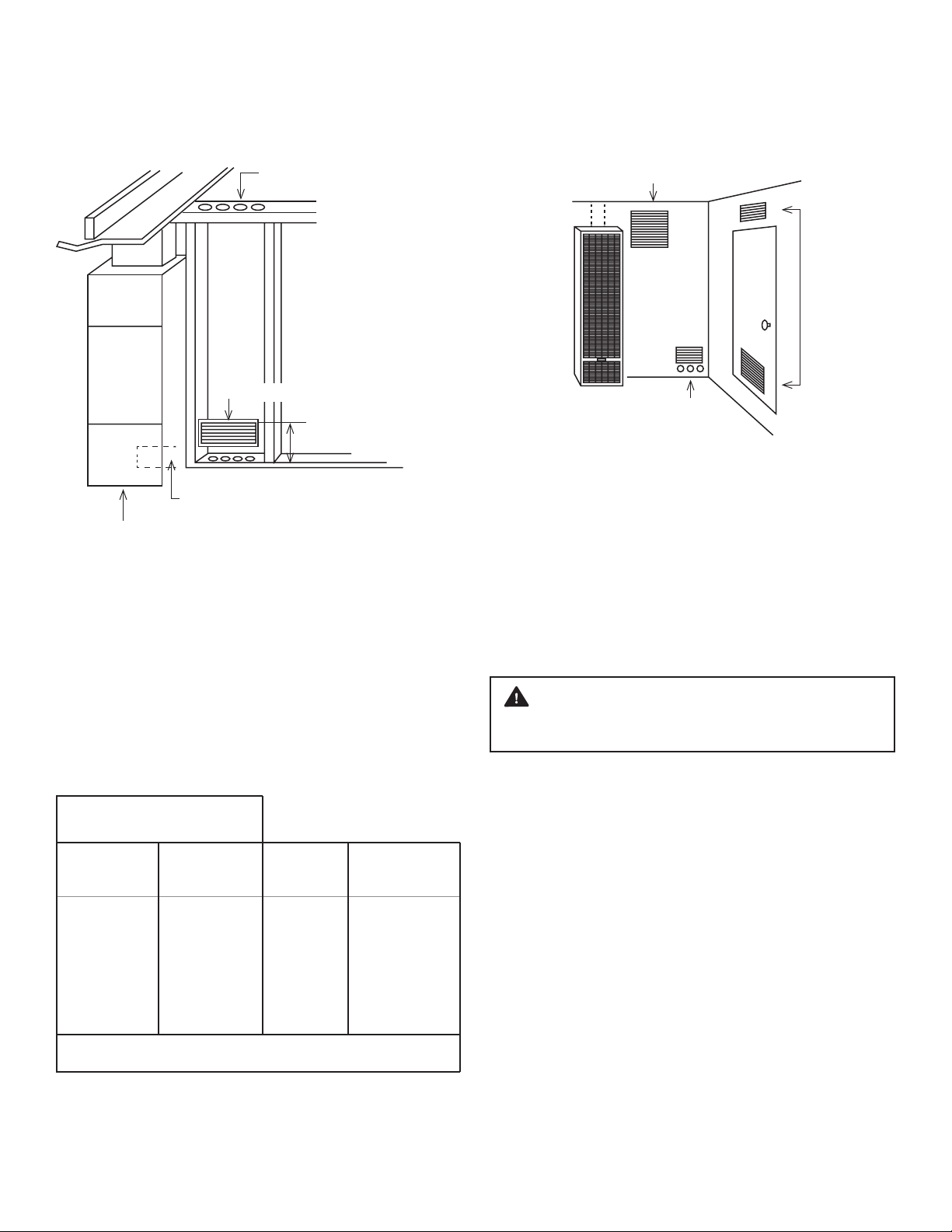
AIR REQUIREMENTS
The requirements for providing air for combustion and
ventilation are listed in the National Fuel Gas Code NFPA
54/ANSI Z223.1 (in Canada: CAN/CGA B149). Most homes
will require that outside air be supplied to the heated area
by means of ventilation grilles or ducts connecting directly
to the outside or spaces open to the outdoors such as attic
or crawl space. The only exception is when the heated area
meets the requirements and definitions for an unconfined
space with adequate air infiltration.
All air openings and connecting ducts must comply with
the following: (continued on next page)
INSTALLING YOUR FURNACE

CARMELTM AC2030TNA TOP VENT GAS WALL HEATER 9
If the furnace is installed in an area with another gas
appliance(s), the total input rating of all appliances must be
considered when determining the free area requirements
for combustion and ventilation air openings.
Ducts must have the same cross-sectional area as the free
area of the openings to which they connect. The minimum
dimension of rectangular air ducts must not be less than
3-inches in length or height.
WARNING: Danger of property damage, bodily
injury or loss of life. Even when a house meets
requirements for unconfined space with adequate air
infiltration, it is recommended that a fresh air intake be
installed to lessen the possible dangers from any future
changes on the home.
LOUVERS GRILLES AND SCREENS COVERING FREE
AREA OPENINGS
If a screen is used to cover the opening(s), it must not be
smaller than 1/4-inch mesh. Use the free area of a louver or grille
to determine the size opening required to provide the free area
specified. If the free area is not known, assume a 20% free area
for wood and a 60% free area for metal louvers or grilles.
INFILTRATION AIR
If your furnace is in an open area (unconfined space), the air
that leaks through the cracks around doors and windows
may be enough for combustion and ventilation air. The doors
should not fit tightly. The cracks around windows should not
be caulked or weather stripped.
Spillage means air starvation. A fresh air duct or air intake
opening must be installed to provide air directly to the
furnace or other gas appliances.
If spillage exists or when the furnace is in a building of tight
construction where the windows and doors are weather
stripped, air for combustion and ventilation must be
obtained from outdoors or space open to the outdoors.
To determine if infiltration air is adequate, perform the
following checks:
1. Close all doors and windows. If you have a fireplace, start
a fire and wait until flames are burning vigorously.
2. Turn on all exhausting devices, i.e., kitchen and bathroom
exhaust fans; water heaters (gas and electric).
3. Turn on all vented gas appliances, i.e., heating equipment
(includes any room heaters), water heaters.
4. Wait ten (10) minutes for drafts to settle.
5. Check for draft hood spillage at each appliance. Hold a lit
match two-inches from the draft opening. (Figure 2).
A. No Spillage
If the match flame pulls toward draft hood, this indicates
sufficient infiltration air. Return exhausting devices and
appliances to the condition you found them.
FIGURE 2 DRAFT HOOD SPILLAGE
If you have a fireplace, open a window or door near the
fireplace and then check for spillage. If spillage stops, do not
use the fireplace without a nearby window or door open until
you can supply fresh air by a permanent duct.
If you have kitchen and bathroom exhaust fans, turn them
off and check for spillage. If spillage stops, do not use exhaust
fans (circuit breakers for fans should be turned off) until you
can supply fresh air by a permanent duct.
Provide opening(s) having a total free area of one-square-
inch per 4,000 BTU/hr. of the total combined input ratings
for all appliances in the area. The required free area is shown
in Figure 3. This fresh air opening or duct must terminate at
a point not more than one-foot above the floor. It must have
at least one-square inch of free area for each 4,000 BTU/hr. of
input of all appliances in area.
FIGURE 3 FREE AREA
Free Area in Square Inches.
Each opening is based on one square inch per 4,000 BTU/hr
BTU/hr input
30,000
35,000
40,000
45,000
50,000
60,000
Square inches
of opening
7.5
8.75
10.00
11.25
12.50
15.00
1 - 1/2
7
8
9
10
11
13
2
4
5
5
6
8
8
3
2
2
3
3
3
4
Required number of holes
sill or header plates
DRAFT HOOD
OPENING
(match or smoke pen)
B. Draft Hood Spills If there is spillage at a draft hood
(match goes out or flame wavers away from draft hood),
check for plugged flue connectors and chimneys. Repair
blockage and test again.

10 CARMELTM AC2030TNA TOP VENT GAS WALL HEATER
HOLE PLACEMENT EXAMPLE
FURNACE LOCATED IN UNCONFINED SPACE
An unconfined space must have a volume of a minimum 50
cubic feet per 1,000 BTU/hr. of the total combined input of
all appliances in the area. Adjoining rooms may be included
only if there are no doors between the rooms or if special
provisions are made such as ventilation grilles installed
between connecting rooms. Figure 4 outlines the minimum
area in square feet, based on 8-foot ceiling heights for various
BTU/hr. input ratings.
FIGURE 4 MINIMUM AREA
EXAMPLES OF GRILL PLACEMENT
FURNACE LOCATED IN CONFINED SPACE
If a furnace is installed in a confined space, it must be
provided with free air for proper combustion and ventilation
of flue gases by one of the following methods:
A. Air From Inside the Building
If the confined space adjoins an unconfined space, provide
two permanent openings. One within 12-inches of the top
and another within 12-inches of the bottom of the room
directly connected to the unconfined space. Each opening
must have a free area of at least 100-square inches or 1-square
inch per 1,000 BTU/hr. of input for all appliances combined.
WARNING: Danger of property damage, bodily
injury or death. The adjoining unconfined space must
have adequate air infiltration.
B. Air From Outdoors
If confined space does not adjoin an unconfined space, then
air must be provided from outdoors or spaces open to the
outdoors such as an attic or crawl spaces.
Openings for inlet or outlet air should NOT be made into an
attic area if the attic is equipped with a thermostat controlled
power vent.
Provide two permanent openings, one within 12-inches of
the top and bottom of the room connecting directly to, or by
using ducts, with the outdoors or areas open to fresh air.
If the opening connects directly to, or with vertical ducts, the free
area of each opening must be at least 1-square inch per 4,000
BTU/hr. of the combined input of all appliances in the area.
If horizontal ducts are used, the free area of each opening
must be at least 1-square inch per 2,000 BTU/hr. of the
combined input of all appliances in the area.
HOLES FROM VENTILATED
ATTIC INTO STUD SPACE
AIR GRILLS TO STUD SPACE
12 MAX FROM FLOOR
HOLES FROM VENTILATED
CRAWL SPACE INTO STUD SPACE
HOLES IN BOTTOM ON BACK OF FURNACE INTO OPEN
STUD SPACE OR CRAWL SPACE
4,000 BTU/hr. per
square inch opening
Round duct dia.
4
4
4
4
4
4 ½
Rectangular
square duct size
3 x 3
3 x 3
3 x 4
3 x 4
3 x 5
3 x 5
*Uncontained space
min. area in sq. ft.
8 ceiling height
145
219
240
281
312
375
Max.
BTU/hr input
30,000
35,000
40,000
45,000
50,000
60,000
* Can be two or more rooms separated by ventilation gas fire.
VENTILATION GRILLES CONNECTING TWO
ROOMS TO MEET UNCONFINED SPACE
100 SQ IN
200 SQ IN
MINIMUM
BETWEEN
LARGE
ROOMS
100 SQ IN
RECOMMENDED FRESH AIR DUCT INTO CRAWL
SPACE IN FURNACE AREA OR IN CLOSET WITH
WATER HEATER
VENTILATION
GRILLES
INTO CLOSET
FOR HOT
WATER
HEATER
INSTALLING YOUR FURNACE

CARMELTM AC2030TNA TOP VENT GAS WALL HEATER 11
WARNING: Danger of illness, bodily injury or death.
Draft hood spillage, with unobstructed vents, indicates
that additional air must be brought into the structure
from the outside. Keep a window open (minimum
2-inches near the appliance until a permanent air duct
is installed.
FIGURE 5 RECESSED WALL MOUNT INSTALLATION
EXAMPLES OF AIR INLETS AND OUTLETS
Recessed Wall Mount
Installation
The maximum recess depth from rear of furnace forward
is 4½-inches.
FIND THE STUDS AND CEILING JOINTS
Use a stud locater or small finishing nails. Repeatedly
drive and remove a nail into the wall in the area of the
stud until it is located. Then find the inside edge of the
stud. Leave the nail at this location.
The other stud should be about 14½-inches from the
one found. Drive finishing nails on the inside of this stud.
Draw wall cutout to required size as shown in Figure 5.
If wall studs are not on 16-inch centers. See “CLOSE OFF
STUD SPACE.” Figure 6
CUT WALL OPENING
Cut wall opening 14⅜-inches wide and 66⅛-inches high
measured from the top of the floor plate. Figure 5, all
corners must be square.
INSTALLATION OF REAR OUTLET REGISTER
The optional rear outlet register may be installed when
the furnace is recessed into the wall. In new construction,
install the rear outlet plaster ground at the same time
you install the header plate. For existing construction,
make the necessary cutout and install the plaster ground
CHIMNEY OR GAS VENT
VENTILATED
ATTIC
OUTLET AIR
OUTLET AIR
INLET AIR
INLET AIR VENTILATED
CRAWL SPACE
10 CRAWL
SPACE
WALL
FURN
TO
ATTIC
12
OPTIONAL INLET AIR 1 SO
INCH PER 4,000 BTU/hr.
100 SQ
INCHES
EACH
1 SQ INCH
PER 4,000 BTU/hr.
MAX
12
2 x 4 STUDS
TOP OF
HEATER
FINISHED
FLOOR
2 X 4
FLOOR
PLATE
14 3/8
66 1/8
GAS STUB
LOCATION
B-W VENT
BASE PLATE
PLASTER TO TOP OF HEADER PLASTER GROUND
REAR REGISTER OPTIONAL FOR SINGLE
BURNER MODELS ONLY
PLASTER GROUND
NAIL FLANGE
8 18X 13 14
CUTOUT
REAR
OUTLET
REGISTER
OPENING
115.V OUTLET
FOR OPTIONAL
BLOWER
TOP OF HEADER
2 x 4
PLATE
ALTERNATE
GAS STUB
LOCATION
14 3/8
A = 4
MODELS
20,500 &
35,000
BTUHR.
A = 2 58
MODELS
50,000
BTUHR.
BOTTOM OF HEADER NAILING FLANGE
9 18
62 14
3 3/4
before you install the furnace. See instructions packed
with accessory and Figure 5.
Do not allow wall finish material to project into the
furnace recess.
Do not install rear outlet register where grille may be
blocked by a door, curtains or any other obstruction.
GAS SUPPLY OPENING
A hole must be drilled for the gas line. Decide whether
the gas line will come through the floor or wall. Drill a 1½-
inch hole through the floor or wall as needed. (Figure 5).
CAUTION: Be careful not to damage any furnace
components while making any alternate hole.

12 CARMELTM AC2030TNA TOP VENT GAS WALL HEATER
CLOSE OFF STUD SPACE (IF REQUIRED)
If studs are not on 16-inch centers, cut the hole for the
furnace next to an existing stud and frame in the other
side using a 2x4 and spacer blocks as required. Figure 6
CEILING PLATE OPENING
Cut away the ceiling plate between the studs where the
furnace is to be installed. Work from the top in the attic.
If there is no access to the top, remove the wall covering
between the two wall studs all the way to the ceiling. Work
through this opening. Cut out the entire plate so the plate
edges will be even with the inner face of the 2 x 4 studs.
Figure 7
INSTALL VENT BASE PLATE HOLDDOWN PLATE
Position base plate on top of header plate and fasten with
screws. Note: Hold down plate is not included.
HEADER PLATE VENT SUPPORT
Measure upward 62¼-inches from the top of the floor plate.
Place a mark on each stud at this distance. Figure 5. Place
the header plate between the studs with the lower edges
even with marks on the studs. Make sure header plate is level.
Locate rear edge of nailing tabs at back of the header. Nail
header plate to the 2 x 4 studs which will center the vent
collar in the wall. Figure 5
FIGURE 6 CLOSE OFF STUD SPACE
FIGURE 7 CEILING PLATE OPENING
CEILING PLATE
EXISTING STUD
FLOOR PLATE
EXISTING STUD
NEW STUD
SPACER
BLOCKS
AS REQ’D
14 38
INSTALL CEILING PLATE SPACER
Nail the ceiling plate spacers either across or in between
the cut out section of ceiling plate. If nailed between, ends
must be bent at 90 degrees. They must be fastened along
each long edge of the ceiling plate hole to hold the oval
vent pipe in the center of the hole. Ceiling plate spacers
preserve structural strength and position oval vent pipe in the
center of the cut out opening. Ceiling plate spacers are not
included.
CEILING PLATE
SPACERS NAILED
IN BETWEEN
CEILING PLATES
OR ACROSS FACE
IF ACCESSIBLE
PLATE SPACER
CEILING PLATE 14 38
2 X 4 STUD
2 X 4 STUD
INSTALLING YOUR FURNACE

CARMELTM AC2030TNA TOP VENT GAS WALL HEATER 13
Surface Mount Installation
The use of the optional Free Standing Accessory No.
4901 allows single-sided furnaces to be surface mounted
instead of recessed into a wall. This is ideal for remodeling
existing masonry wall construction or when studding is
substandard. This kit drastically cuts installation time and
eliminates the expense of cutting into the walls and ceiling
plates. Be sure this accessory is of the type and design
required for the use with your furnace.
NOTE: After picking a location that meets the
requirements, check the wall, attic, and roof to make sure
there are no obstructions such as pipes, electrical wiring,
etc., which could interfere with the installation of the
furnace or vent pipe. If required, move them or pick a
new location.
FIND THE WALL STUDS OR CEILING JOISTS
Find two studs or joists at the spot where the furnace is
to be located. Use a stud locater or small finishing nails.
Repeatedly drive and remove a nail into the wall or ceiling
in the area of the stud or joust until you find it. Then find
the its side and leave the nail there. Drive another nail just
on the other side other the same stud or joist.
The inside of the next stud or joist should be about 14½
inches from the first one found. Drive a nail on the inside of
this stud or joist.
Using the nails as a guide, draw two lines down the side of
the wall from the ceiling to locate the furnace and ceiling
hole cutout for venting.
FREE STANDING ACCESSORY ASSEMBLY & INSTALLATION
1. Attach the base plate panel as shown in Figure A to the
bottom of the side rails with four (4) # 6, ⅜” screws.
2. Attach the header plate, (included with the furnace), to
the side rails using four (4) #8, ⅜” screws. Flanges of the
header plate go against the wall. Figure A.
3. Install extension side rails as shown in Figure A, by
telescoping them inside the lower side rails. Adjust the
extension side rails by sliding them up or down to
ceiling height. Maximum: 8 feet 9 inches, Minimum:
7 feet 9 inches.
4. If the wall has a baseboard, cut the baseboard out to fit
against the side rails. Stand the side rails against the
wall and fasten them to the wall securely with screws
or bolts in the holes provided. Use a level to assure the
enclosure is plumb. Screws and bolts for wall
fastening are not included.
5. After positioning the enclosure, cut a 3½ X 14 inch hole
in the ceiling, centered between the studs or joists as
shown in Figure B.
6. Cut ¼ inch off each end of the ceiling spacer plate.
Place the ceiling spacer plate to the back of the wall
and centered in the enclosure as shown in Figure C.
7. Install Type B/W vent though the roof and studs or
joists in accordance with the installation instructions
packed with the furnace and local codes. See Vent
Installation, page 14-15.
8. Set the furnace body into position. Figure 10, page 16.
The furnace legs will rest on the bottom of the base
plate panel. Utilizing the holes provided in the furnace
legs, secure the furnace to the brackets attached to the
bottom panel with two (2) #10, ¾” screws.
9. Install the vent enclosure panel, fastening it to the side
rails with six (6) #6, ⅜” screws. Trim the bottom of the
panel to fit the header plate.
10. Install gas inlet through the back wall or one of the two
holes provided in the bottom base plate panel.
Figure D Connect gas line to furnace. See Gas supply
and Piping, page 17.
11. Install furnace face panel. See Front Panel Installation,
page 19. NOTE: The panel recesses ¼-inch between the
vertical edges of the enclosure.
FIGURE A
HEADER PLATE
SIDE RAIL
SIDE RAIL
BASE PLATE PANEL

14 CARMELTM AC2030TNA TOP VENT GAS WALL HEATER
FIGURE B
FIGURE D
FIGURE C
VENT INSTALLED
FRONT PANEL INSTALLED
STUD WALL
CENTERED
14
3 12
STUD WALL
GAS STUB LOCATIONS
STUD WALL
STUD WALL
16
4 716
A
PLUMBERS
TAPE
BW VENT PIPING
CEILING PLATE SPACER
VENT
HOLD DOWN
PLATE
HEADER
FURNACE
SIDE RAIL
BASE PLATE
PANEL
INSTALLING YOUR FURNACE

CARMELTM AC2030TNA TOP VENT GAS WALL HEATER 15
Vent Installation
The vent installation must comply with all local codes and
ordinances. If in doubt, consult your local codes or inspector.
The furnace vent must be directed to the outdoors so that
harmful combustion gases will not collect inside the building.
This furnace must not be connected to a chimney flue
serving a separate solid-fuel burning appliance.
This product design is certified to ANSI Z21.86. It must be
installed with a U.L. tested and listed type “B” approved vent
and type “B/W” approved vent, Figure 8. Older style terra-
cotta, transite pipe, clay, concrete or masonry type vent pipe
cannot be used with this appliance. These types of vent
pipe will not heat fast enough to establish a draft, which
will result in improper venting of combustion products.
FIGURE 8 TYPICAL VENT INSTALLATION
VENT CAP MUST BE MINIMUM 2 FEET
HIGHER THAN ANY POINT WITHIN
10 FEET OF THE VENT CAP
10 FEET
LISTED
VENT CAP
STORM
COLLAR
ROOF
FLASHING
HEIGHT FROM HEADER PLATE
TO THE VENT CAP TOP MUST
BE 6 FEET MINIMUM
1 INCH MIN. CLEARANCE TO COMBUSTIBLES
LISTED 4ROUND B VENT
OVAL TO ROUND
ADAPTER
OVAL BW VENT
DOUBLE WALL
PLATE SPACER
RECESSED MOUNT
2 REQUIRED
BASE PLATE HOLD DOWN
OR STARTER PLATE SCREWED
DOWN TO HEADER PLATE
NOTE: THESE PARTS ARE SUPPLIED WITH THE FURNACE
GASKET
HEADER PLATE AND GASKETS
PROVIDED WITH FURNACE
FIGURE 8 ALTERNATIVE VENTING
IF VENT EXTENDS OVER 5 FEET
ABOVE ROOF, GUY OR BRACE.
SEAL AROUND COLLAR
AND FLASHING
MAINTAIN LISTED
CLEARANCE
LOCK JOINTS
SUPPORT LATERALS
MAXIMUM VERTICAL RISE
MAINTAIN
LISTED
CLEARANCE
SUPPORT IF
NECESSARY
TYPE B ROUND OR OVAL
INSULATION SHIELD,
IF ATTIC IS INSULATED
ATTACH
HEADER
PLATE
MINIMUM
HEIGHT
12 FEET
FIRE STOP
SPACE
MULTISTORY
UPPER FLOORS
SHEET
METAL
SLEEVE
CEILING
SPACER
SINGLE STORY
OR FIRST FLOOR
OF MULTISTORY
SEAL AND
BASE PLATE
HEATER HEADER
PLATE

16 CARMELTM AC2030TNA TOP VENT GAS WALL HEATER
Attaching Your Furnace
Clear the wall recess of all debris, remove any wood or plaster.
Stand the furnace in front of recess, holding the furnace body
at an angle. Insert flue collar into the opening in the header
plate and raise furnace carefully, Figure 10. Swing bottom of
furnace into wall recess with front edges of legs flush with
2x4 floor plate. In the holes provided, nail through the legs
into studs or floor plate, Figure 11.
Do not damage gasket glued to underside of header plate
when placing furnace in wall. Avoid nailing the legs so tightly
that it disturbs the inner furnace casing. Do not try to force
the furnace into a smaller-than-specified recess.
If an existing gas line is preventing the installation of the
furnace, a cut-out may be made using tin snips on one of
the legs to clear this existing gas line. This cut-out will be on
one side of the unit on the rear side of the leg and only if
necessary.
FIGURE 10 INSERT FURNACE
FIGURE 11 NAIL PLACEMENT
BW VENT
BOTTOM OF
FURNACE
NAIL FURNACE LEG TO
STUD OR FLOOR PLATE
SEE DETAIL BELOW
FLOOR PLATE
LEG
NAIL AT
ANGLE
BOTTOM OF FURNACE
INSTALLING YOUR FURNACE
Consequently, this could cause the vent safety control
system to shut down the furnace.
The area above header within the stud space MUST be kept
clear of any attic insulation to allow the free circulation of
air around the oval vent piping. In some areas the building
code requires the use of an attic shield.
The B/W vent must extend through the ceiling and roof
terminating at least 12-feet above the finished floor on
which the furnace rests.
The vent should also be pressed down until the vent
presence switch on the header plate makes a clicking
sound, as shown below in Figure 9.
INSTALL FURNACE VENT
Attach a 4-foot length of oval, double-wall vent pipe
through the plate spacers to the hold-down plate. Push
the vent pipe into the hold-down plate until it is completely
seated. The hold-down cleat will engage the groove in the
vent pipe.
COMPLETE THE VENTING
Type B/W gas vent shall extend from the header plate of
the furnace to a point above the highest ceiling plate within
the stud space through which the vent passes, without any
offsets or crossovers. The first vent pipe offset, (if required),
may not be any closer than 2-feet from the header and
needs to extend past the ceiling plate. After a type B/W gas
vent passes through the highest ceiling plate within a stud
space above the furnace to which it serves, the vent system
may be completed with a Type B gas vent, from the SAME
manufacturer (do not mix brands of pipe). Offsets cannot
be greater than 45 degrees from vertical. Refer to The
Uniform Mechanical Code.
Install the oval-to-round adapter. Complete the piping
extending it through the roof. Use a 4-inch round, double-
wall (Type B) vent pipe, roof flashing, storm collar and vent
cap as shown. The vent cap must be at least 2-feet higher
than any point that is within 10- feet of the vent cap. There
must be at least a 1-inch clearance between the vent pipe
and any combustible material.
CAUTION: To avoid damage to wiring, be sure to route
the wires away from the path of the furnace vent.
FIGURE 9 VENT PRESENCE SWITCH
VENT SHOULD BE
PRESSED DOWN
UNTIL CLICKING
NOISE IS HEARD.

CARMELTM AC2030TNA TOP VENT GAS WALL HEATER 17
FIGURE 12 REMOVE KNOCKOUT PLATES
REAR OUTLET KIT INSTALLATION (OPTIONAL)
If the Rear Outlet Register Accessory kit 6920 is used, the
following procedure must be completed before placing
furnace body into wall recess, Figure 12. Attach speed nuts
to outer shield and remove knockout plates from both the
outer and inner shields as follows:
1. Punch in the lower corners with a screwdriver blade.
2. Break the knockout side and bottom connecting tabs
by holding a screwdriver blade sideways against the
tab and striking the head of the screwdriver lightly
with a hammer.
3. Swing the plate outward; bend it back and forth to
break the top tabs. Use caution when handling sharp
metal edges.
CAUTION: Do not install rear outlet kit where grille may
be blocked by a door, curtains, or any other obstruction.
WARNING: Never shear or cut the furnace legs.
INNER SHIELD
KNOCKOUT PLATE
ON OUTER SHIELD
HOLD SCREWDRIVER
SIDEWAYS AGAINST
TABS AND STRIKE
LIGHTLY WITH
HAMMER
10 24 SPEED NUT
After furnace is in position, install rear outlet register as shown
in Figure 13. Have damper in open position when inserting
the assembly. Secure the rear outlet register to speed nuts
with the machine screws furnished.
FIGURE 13 MOUNTING REAR OUTLET REGISTER
Gas Supply and Piping
The gas control valve, in the furnace, is shipped with a seal
over the gas inlet tapping. Do not remove the seal until ready
to connect the piping.
WARNING: Danger of property damage, bodily
injury or death. Make sure the furnace is equipped to
operate o the type of gas available. Models designed
as natural gas are to be used with natural gas only.
Models designed for use with liquefied petroleum
propane gas have orifices sized for commercially pure
propane gas. They cannot be used with butane or a
mixture of butane and propane.
GAS SUPPLY
For natural gas, the minimum inlet gas supply pressure
for the purpose of input adjustment is 5-inches water
column. The maximum inlet gas supply pressure is
7-inches water column.
Gas pressure and input to the burners must not exceed
the rated input and pressure shown on the nameplate.
REGISTER
ASSEMBLY
HEAT SENSOR
SWITCH
BLOWER AND
MOTOR
FURNACE
SHEILDS

18 CARMELTM AC2030TNA TOP VENT GAS WALL HEATER
All piping must comply with local codes and ordinances
or with the National Fuel Gas Code (ANSI Z223.1 NFPA No.
54), whichever applies. (In Canada: CAN/C.GA B149). Refer
to FIGURE 15 for the general layout of the unit. It shows the
basic fittings needed.
The following rules apply:
1. Use new, properly reamed steel or black iron pipe and
fittings free of metal chips and debris that are approved by
local codes. Metal chips and debris can damage the valve.
2. Do not thread pipe too far. Valve distortion or malfunction
may result from excess pipe within the gas control valve.
Apply a moderate amount of good quality dope to the
pipe only. Leave the two end threads bare. (Figure 17).
3. Use ground joint unions.
4. Install a drip leg (sediment trap) to trap dirt and moisture
before it can enter the gas valve. The nipple must be a
minimum of 3-inches long.
5. Install a manual shutoff valve.
6. Provide a 1/8” NPT test gauge connection immediately
before the gas supply connection to the furnace.
FIGURE 14 PIPE CAPACITY
ORIFICE SIZES
The efficiency rating of this appliance is a product Annual
Fuel Utilization Efficiency rating determined under
continuous operating conditions and was determined
independently of any installed system.
This furnace is equipped with a automatically controlled
modulating valve and power burner. For elevations above
2,000 feet, adjust thermostat settings to the appropriate
elevation during installation.
The gas supply line must be of adequate size to handle the
BTU/hr. requirements and length of the run for the unit
being installed.
Determine the minimum pipe size from Figure 14, based on
the length of the run from the gas meter to the unit.
PIPE CAPACITY BTUhr. WITH FITTINGS
NATURAL GAS
LENGTH
OF PIPE
FEET
PIPE SIZE
1/2”
3/4” 1”
20
40
60
92,000
63,000
50,000
190,000
130,000
105,000
350,000
245,000
195,000
GAS CONNECTION
Use two pipe wrenches when making the connection to
the valve to prevent turning and/or damage to the valve
or orifice. Use one pipe wrench to maintain the valve’s
position and use another to install the gas nipple and line.
Refer to Figure 16 below.
Connections between the manual shutoff valve and burner
control assembly can be made with an A.G.A./C.G.A. design
certified flexible connector if allowed by local codes. Drip
leg and ground joint unions are still required.
Tighten all joints securely including orifice and manifold.
Test all piping for leaks. When checking gas piping to the
furnace with gas pressure less than 1/2 PSI, shut off manual
gas valve to the furnace. If gas piping is to be checked with
the pressure at or above 1/2 PSI, the furnace and manual
shutoff valve must be disconnected during testing. (SEE
WARNING). Apply soap solution (or a liquid detergent) to
each joint. Bubbles forming indicate a leak. Correct even
the slightest leak at once.
WARNING: Danger of property damage, bodily injury
or death. Never use a match or open flame to test for
leaks. Never exceed specified pressures for testing. Higher
pressures may damage the gas valve and cause over-
firing which may result in component(s) failure. Never
attempt start-up of unit before thoroughly ventilating the
area and smelling near the floor for gas odor.
INSTALLING YOUR FURNACE
FIGURE 16 VALVE CONNECTION
USE FIRST WRENCH
TO HOLD VALVE
FIRMLY IN PLACE.
USE SECOND WRENCH TO
HOLD FITTING. TURN
WRENCH COUNTER-
CLOCKWISE TO TIGHTEN
THE FITTING TO THE VALVE.

CARMELTM AC2030TNA TOP VENT GAS WALL HEATER 19
FIGURE 15 GAS PIPING
MANUAL SHUTOFF VALVE
18NPT
PLUGGED
HOLE FOR
TEST
GAUGE
DROP
GROUND JOINT UNION
GAS
VALVE
GAS
VALVE
GAS
VALVE
PIPED GAS SUPPLY
PIPED GAS SUPPLY
TUBING GAS SUPPLY
CAUTION: Shut off the main gas supply before removing the end cap to prevent
gas from filling the work area. Test for gas leakage when installation is complete.
2
CAUTION: All bends in metal tubing must be smooth.
1
2CAP
2CAP
2CAP
1
HORIZONTAL
3 76.2 MM MINIMUM
3 76.2 MM
MINIMUM
3 76.2 MM MINIMUM
MANUAL SHUTOFF VALVE
MANUAL
SHUTOFF VALVE
NIPPLE
TEE
FITTING
NIPPLE
TEE
FITTING
NIPPLE
RISER
RISER
DROP
HORIZONTAL
GROUND JOINT
UNION
GROUND JOINT UNION
FIGURE 17 PROPER PIPING PRACTICE
PROPER PIPE
THREADING
INCORRECT
THREADING
2 THREADS EXPOSED
SEALANT THIN
ENOUGH TO SHOW
THREADS
OVERTHREADED
SEALANT
TOO THICK
SEALANT
PAST TIP
DAMAGED
THREADS
Front Panel Installation
Place the front panel top over the channel on the header
plate, as shown in Figure 18. Press the panel tight against
wall, and secure it to the header channel with the screw
provided in final assembly package. Open the control
door at bottom of panel and fasten the panel at each side
through slots in flanges with screws provided.
Attach handle to the front panel door with the screw
provided.
Install the second face panel in same manner for 500
Series models.
FIGURE 18 PANEL PLACEMENT

20 CARMELTM AC2030TNA TOP VENT GAS WALL HEATER
Thermostat Installation
Use the thermostat supplied with the unit.
1. Use cable supplied with the unit.
2. If a new location is chosen or if this is a new installation,
thermostat cable must first be run to the location
selected. These instructions cover bringing the cable
down from the attic but it may be run from a
basement or crawl space using similar methods.
3. Before drilling a hole in the wall at the selected location,
drive a small finish nail through the ceiling in the
corner of the wall and ceiling above the thermostat
location. Pull the nail out and push a small, stiff wire
through the hole so it can be found in the attic.
Drill a ½-inch hole through the ceiling wall plate.
4. Probe for obstructions in the partition. Then, drill a
½-inch to 1-inch hole through the wall at the selected
location for the thermostat.
5. From the attic, feed the thermostat cable through the
wall until even with the thermostat location.
IMPORTANT: Keep the thermostat cable away from the combustion
chamber.
Access Settings/Back
Date
Decrease Set Temp/Scroll Down
Confirm/Select
Increase Set Temp/Scroll Up
Set Temperature
BTU Output Level
Room Temperature
FIGURE 19 THERMOSTAT SETTINGS
Settings
Mode
Time
INSTALLING YOUR FURNACE
6. Snag the thermostat cable through the hole and pull
the cable through the hole in the wall so that 6-inches
of the cable protrude.
7. Route cable to the furnace.
8. Never use nails or staples across the thermostat cable.
WALLMOUNTED THERMOSTAT INSTALLATION
1. Mount thermostat mounting plate on wall making sure
the opening on the plate matches up with the hole in
the wall were the thermostat cable will be threaded
through.
2. Thread thermostat cable through the hole in the wall
and mounting plate.
3. Connect thermostat cable to thermostat.
4. Mount thermostat onto mounting plate.
NOTE: A step-by-step “Customer Thermostat Settings” instructions sheet is included in your shipping
box. These instruction will guide you through programming your thermostat and other important
settings. This instruction document can also be found online at:
https://www.williamscomfortprod.com/products/furnaces/tg2030t
Table of contents
Other Williams Heater manuals

Williams
Williams AC2030T User manual

Williams
Williams CARMEL TG2030TN User manual

Williams
Williams 696542 Quick start guide

Williams
Williams 1286513 User manual

Williams
Williams 3501522A User manual

Williams
Williams 2696541 Quick start guide

Williams
Williams 1773512 Quick start guide

Williams
Williams 1753012 User manual

Williams
Williams Slim Tech Series Assembly instructions

Williams
Williams 4007332 User manual