Wilo Wilo-DrainLift KH 32-0,4 User manual

Einbau- und Betriebsanleitung
Installation and operating Instructions
Notice de montage et de mise en service
Onderhouds- en bedieningsvoorschriften
Instrucciones de instalación y funcionamiento
Istruzioni di montaggio, uso e manutenzione
Beépítési és üzemeltetési utasítás
Instalacja i instrukcje obsługi
Návod k montáˇzí a obsluze
Οδηγίες εγκατάστασης και λειτουργίας
Instrukciå po montaøu i zkspluatacii
Monterings- och skötselanvisning
Wilo-Drain-Lift KH 32-0,4
D
GB
F
NL
E
I
H
PL
CZ
GR
RUS
S
Pumpen-Perfektion
und mehr . . .
2044035/ 2002.10 DDD

Fig. 1

Fig. 2

Fig. 3

Fig. 5
Fig. 4

DCE-Konformitäts-
erklärung
Hiermit erklären wir, daß die-
ses Aggregat folgenden ein-
schlägigen Bestimmungen
entspricht:
EG-Maschinenrichtlinien
89/392/EWG i.d.F.,
91/368/EWG, 93/44/EWG,
93/68/EWG
Elektromagnetische
Verträglichkeit
89/336/EWG i.d.F.
92/31/EWG, 93/68/EWG
Angewendete harmonisierte
Normen, insbesondere
EN 809, EN 50 081-1,
EN 50 082-1, EN 50 081-2,
EN 50 082-2.
GB EC declaration of
conformity
We hereby declare that this
unit complies with the
following relevant provisions:
EC machinery directive
89/392/EWG in this version,
91/368/EWG, 93/44/EWG,
93/68/EWG
Resistance to
electromagnetism
89/336/EWG in this version
92/31/EWG, 93/68/EWG
Applied harmonized stan-
dards in particular:
EN 809, EN 50 081-1,
EN 50 082-1, EN 50 081-2,
EN 50 082-2.
FDéclaration de
conformité CE
Par la présente, nous
déclarons que cet
agrégat sitisfait aux
dispositions suivantes:
Directives CEE relatives
aux machines 89/392/CEE,
91/368/CEE, 93/44/CEE,
93/68/CEE
Compatibilité
électromagnétique
89/336/CEE, 92/31/CEE,
93/68/CEE
Normes utilisées harmo-
nisées, notamment
EN 809, EN 50 081-1,
EN 50 082-1, EN 50 081-2,
EN 50 082-2.
NL EG-verklaring van
overeenstemming
iermede verklaren wij dat
deze machine voldoet aan
de volgende bepalingen:
EG-richtlijnen betreffende
machines 89/392/EEG,
91/368/EEG, 93/44/EEG,
93/68/EEG
Elektromagnetische
tolerantie
89/336/EEG, 92/31/EEG,
93/68/EEG
Gebruikte geharmoniseerde
normen, in het bijzonder
EN 809, EN 50 081-1,
EN 50 082-1, EN 50 081-2,
EN 50 082-2.
EDeclaración de
conformidad CE
Por la presente declaramos
que esta unidad satisface las
disposiciones pertinentes
siguientes:
Directivas CE sobre
máquinas 89/392/CEE,
91/368/CEE, 93/44/CEE,
93/68/CEE
Compatibilidad electro-
magnética 89/336/CEE,
92/31/CEE, 93/68/CEE
Normas armonizadas
utilizadas particularmente
EN 809, EN 50 081-1,
EN 50 082-1, EN 50 081-2,
EN 50 082-2.
IDichiarazione di
conformità CE
Con la presente si dichiara
che le presenti pompe sono
conformi alle seguenti
direttive di armonizzazione
Direttiva Macchine CEE
89/392/CEE, 91/368/CEE,
93/44/CEE, 93/68/CEE
Compatibilità
elettromagnetica
89/336/CEE, 92/31/CEE,
93/68/CEE
Norme armonizzate applica-
te, in particolare
EN 809, EN 50 081-1,
EN 50 082-1, EN 50 081-2,
EN 50 082-2.
SF CE-standardinmukai-
suusseloste
Ilmoitamme täten, että tämä
laite vastaa seuraavia
asiaankuuluvia määräyksiä:
EY-konedirektiivit
89/392/ETY, 91/368/ETY,
93/44/ETY, 93/68/ETY
Sähkömagneettinen
soveltuvuus
89/336/ETY, 92/31/ETY,
93/68/ETY
Käytetyt yhteensovitetut
standardit, erityisesti
EN 809, EN 50 081-1,
EN 50 082-1, EN 50 081-2,
EN 50 082-2.
SEEC konformitets-
deklaration
Härmed förklaras att denna
maskin uppfyller följande
bestämmelser:
EEC maskindirektiv
89/392/EEC i denna version,
91/368/EEC, 93/44/EEC,
93/68/EEC
Elektromagnetisk kompati-
bilitet 89/336/EEC i denna
version, 92/31/EEC,
93/68/EEC
Tillämpade harmoniserade
normer, särskilt:
EN 809, EN 50 081-1,
EN 50 082-1, EN 50 081-2,
EN 50 082-2.
HEK. azonossági
nyilatkozat
Ezennel kijelentjük, hogy az
agregát a megkívánt alanti
feltételeknek
megfelel:
EK-Gépirányelvek
89/392/EWG, 91/368/EWG,
93/44/EWG, 93/68/EWG
Elektromagnetikus
ÖsszeegyeztethetŒség
89/336/EWG, 92/31/EWG,
93/68/EWG
Alkalmazott, harmonizált
normák, különösen az
EN 809, EN 50 081-1,
EN 50 082-1, EN 50 081-2,
EN 50 082-2.

GR ∆ήλωση συµµρφωσης
µε τους κανονισµούς CE
∆ηλώνουµε τι το προϊν
αυτ ικανοποιεί τις
ακλουθες διατάξεις:
Οδηγίες CEE σχετικά
µε µηχανήµατα
89/392/CEE, 91/368/CEE,
93/44/CEE, 93/68/CEE
Ηλεκτροµαγνητική
συµβαττητα
89/336/CEE, 92/31/CEE,
93/68/CEE
Εναρµονισµένα
χρησιµοποιούµενα
πρτυπα, ιδιαίτερα
EN 809, EN 50 081-1,
EN 50 082-1, EN 50 081-2,
EN 50 082-2.
CZ Osvûdãení o shodnosti s
normami EU
Prohla‰ujeme tímto, Ïe toto
zafiízení odpovídá následu-
jícím pfiíslu‰n˘m ustanovením:
Smûrnice o strojírenském
zafiízení ES 89/392/EHS
vãetnû dodatkÛ,
91/368/EHS, 93/44/EHS,
93/68/EHS
Elektromagneticá sná‰en-
livost 89/336/EHS vãetnû
dodatkÛ, 92/31/EHS,
93/68/EHS
PouÏité souhlasné normy,
zejména:
EN 809, EN 50 081-1,
EN 50 082-1, EN 50 081-2,
EN 50 082-2.
PL OÊwiadczenie
zgodnoÊci EC
Niniejszym oÊwiadczamy, ˝e
pompa odpowiada nast´pujà-
cym w∏aÊciwym dla niej
dyrektywom:
Wytyczne dla przemys∏u
maszyncwego EC
89/392/EEC w tej wersji,
91/368/EEC, 94/44/EEC,
93/68/EEC
OdpornoÊç elektroma-
gnetyczna EC 89/336/EEC
w tej wersji, 92/31/EEC,
93/68/EEC
Zastosowano normy zharmo-
nizowane, w szczególnoÊci:
EN 809, EN 50 081-1,
EN 50 082-1, EN 50 081-2,
EN 50 082-2.
RUS Zaåvlenie o sootvetst-
vii normam, dejst-
vuœwim v Evropejs-
kom Soob-westve
Nastoåwim dokumentom
zaåvlåem, hto dannaå usta-
novka sootvetstvuet sle-
duœwim postanovleniåm:
Директивы EC относи-
тельно машин и станков
89/392/ЦЕЕ, 91/368/ЦЕЕ,
93/44/ЦЕЕ, 93/68/ЦЕЕ
Qlektromagnitnaå sov-
mestimostæ 89/336/CEE,
92/31/CEE, 93/68/CEE
Ispolæzovavπieså garmo-
nizirovannye standarty i
normy, v hastnosti
EN 809, EN 50 081-1,
EN 50 082-1, EN 50 081-2,
EN 50 082-2.
DK EF-overensstemmels-
eserklæring
Det erklæres hermed, at
dette udstyr er i overens-
stemmelse med følgende
bestemmelser:
EU maskindirektiver:
89/392/EØF i denne
udgave, 91/368/EØF,
93/44/EØF, 93/68/EØF
Elektromagnetisk
kompatibilitet:
89/336/EØF i denne udga-
ve, 92/31/EØF, 93/68/EØF
Anvendte harmoniserede
normer, især:
EN 809, EN 50 081-1,
EN 50 082-1, EN 50 081-2,
EN 50 082-2.
NEU-overensstemmelse-
serklæring
Det erklæres herved at dette
utstyret stemmer overens
med følgende bestemmel-
ser:
EU-direktiver for maskiner
89/392/EEC og følgende,
91/368/EEC, 93/44/EEC,
93/68/EEC
Elektromagnetisk
kompatibilitet
89/336/EEC og følgende,
92/31/EEC, 93/68/EEC
Anvendte harmoniserte nor-
mer, i særdeleshet
EN 809, EN 50 081-1,
EN 50 082-1, EN 50 081-2,
EN 50 082-2.
TR Uygunluk Belgesi
As¸agˇí´daki cihazlarí´n takibi
standartlara
vygun oldugˇ unu temin
ederiz:
AB-Makina Standartlari
89/392/EWG i.d.F.,
91/368/EWG, 93/44/EWG,
93/68/EWG
Elektromanyetik
Uyumluluk
89/336/EWG i.d.F.,
92/31/EWG, 93/68/EWG
Özellikle kullaní´lan Normlar
EN 809, EN 50 081-1,
EN 50 082-1, EN 50 081-2,
EN 50 082-2.
2011678.3
WILO AG
Nortkirchenstraße 100
44263 Dortmund · Germany
Quality Management

3
D
1. Allgemeines . . . . . . . . . . . . . . . . . . . . . . . . . 5
2. Sicherheit . . . . . . . . . . . . . . . . . . . . . . . . . . . 5
3. Transport und Zwischenlagerung. . . . . . . . . 6
4. Beschreibung des Erzeugnisses . . . . . . . . . 6
5. Aufstellung/Einbau . . . . . . . . . . . . . . . . . . . . 7
6. Inbetriebnahme . . . . . . . . . . . . . . . . . . . . . . 8
7. Wartung . . . . . . . . . . . . . . . . . . . . . . . . . . . . 8
8. Störungen, Ursachen und Beseitigung . . . . 9
GB
1. General Information . . . . . . . . . . . . . . . . . . . 10
2. Safety precautions . . . . . . . . . . . . . . . . . . . . 10
3. Transport and storage . . . . . . . . . . . . . . . . . 11
4. Description of product and accessories . . . 11
5. Assembly and installation . . . . . . . . . . . . . . 12
6. Starting up . . . . . . . . . . . . . . . . . . . . . . . . . . 13
7. Maintenance. . . . . . . . . . . . . . . . . . . . . . . . . 13
8. Faults, causes and remedies . . . . . . . . . . . . 14
F
1. Généralités . . . . . . . . . . . . . . . . . . . . . . . . . . 15
2. Sécurité . . . . . . . . . . . . . . . . . . . . . . . . . . . . 15
3. Transport et stockage
avant utilisation . . . . . . . . . . . . . . . . . . . . . . 16
4. Description du produit . . . . . . . . . . . . . . . . . 16
5. Installation/Montage . . . . . . . . . . . . . . . . . . 17
6. Mise en service . . . . . . . . . . . . . . . . . . . . . . 17
7. Entretien. . . . . . . . . . . . . . . . . . . . . . . . . . . . 17
8. Défauts, causes et remèdes . . . . . . . . . . . . 19
NL
1. Algemeen . . . . . . . . . . . . . . . . . . . . . . . . . . . 20
2. Veiligheid . . . . . . . . . . . . . . . . . . . . . . . . . . . 20
3. Transport en tussenopslag. . . . . . . . . . . . . . 21
4. Beschrijving van het product . . . . . . . . . . . 21
5. Opstelling/Montage . . . . . . . . . . . . . . . . . . . 22
6. Inwerkingstelling . . . . . . . . . . . . . . . . . . . . . 23
7. Onderhoud . . . . . . . . . . . . . . . . . . . . . . . . . . 23
8. Storingen, oorzaken en oplossingen . . . . . . 24
E
1. Generalidades . . . . . . . . . . . . . . . . . . . . . . . 25
2. Instrucciones de seguridad . . . . . . . . . . . . . 25
3. Transporte y almacenamiento . . . . . . . . . . . 26
4. Descripción del producto. . . . . . . . . . . . . . . 26
5. Colocación/Instalación. . . . . . . . . . . . . . . . . 27
6. Puesta en funcionamiento . . . . . . . . . . . . . . 28
7. Mantenimiento . . . . . . . . . . . . . . . . . . . . . . . 28
8. Fallos: causas y eliminación . . . . . . . . . . . . 29
I
1. Generalità. . . . . . . . . . . . . . . . . . . . . . . . . . . 30
2. Sicurezza . . . . . . . . . . . . . . . . . . . . . . . . . . . 30
3. Trasporto e magazzinaggio . . . . . . . . . . . . . 31
4. Descrizione del prodotto
e accessori. . . . . . . . . . . . . . . . . . . . . . . . . . 31
5. Montaggio/Installazione . . . . . . . . . . . . . . . 31
6. Messa in esercizio . . . . . . . . . . . . . . . . . . . . 32
7. Manutenzione. . . . . . . . . . . . . . . . . . . . . . . . 32
8. Blocchi, cause e rimedi. . . . . . . . . . . . . . . . 34

4
H
1. Általános tudnivalók. . . . . . . . . . . . . . . . . . . 35
2. Biztonsági elo´´írások. . . . . . . . . . . . . . . . . . . 35
3. Szállítás és ideiglenes tárolás . . . . . . . . . . . 36
4. A termék ismertetése . . . . . . . . . . . . . . . . . . 37
5. Felállítás/beépítés . . . . . . . . . . . . . . . . . . . . 37
6. Üzemeltetés . . . . . . . . . . . . . . . . . . . . . . . . . 38
7. Karbantartás. . . . . . . . . . . . . . . . . . . . . . . . . 38
8. Üzemzavarok, azok okai
és elhárításuk . . . . . . . . . . . . . . . . . . . . . . . . 40
CZ
1. Obecně. . . . . . . . . . . . . . . . . . . . . . . . . . . . . 46
2. Bezpečnost . . . . . . . . . . . . . . . . . . . . . . . . . 46
3. Přeprara a skladování . . . . . . . . . . . . . . . . . 47
4. Popis výrobku . . . . . . . . . . . . . . . . . . . . . . . 47
5. Instalace/montáž . . . . . . . . . . . . . . . . . . . . . 48
6. Uvedení do provozu. . . . . . . . . . . . . . . . . . . 49
7. Údržba . . . . . . . . . . . . . . . . . . . . . . . . . . . . . 49
8. Poruchy, jejich příčiny a odstraňování . . . . . 50
S
1. Allmänt . . . . . . . . . . . . . . . . . . . . . . . . . . . . . 63
2. Säkerhet . . . . . . . . . . . . . . . . . . . . . . . . . . . . 63
3. Transport och mellanlagring. . . . . . . . . . . . . 64
4. Produkt- och tillbehörsbeskrivning . . . . . . . 64
5. Placering och installation . . . . . . . . . . . . . . . 65
6. Igångsätting . . . . . . . . . . . . . . . . . . . . . . . . . 66
7. Skötsel . . . . . . . . . . . . . . . . . . . . . . . . . . . . . 66
8. Fel, orsaker och åtgärder. . . . . . . . . . . . . . . 67
PL
1. Uwagi ogólne . . . . . . . . . . . . . . . . . . . . . . . . 41
2. Bezpieczneństwo użytkowania. . . . . . . . . . . 41
3. Transport i tymczasowe
przechowywanie . . . . . . . . . . . . . . . . . . . . . 42
4. Opis wyrobu i wyposażenie . . . . . . . . . . . . . 42
5. Montaż i instalacja . . . . . . . . . . . . . . . . . . . . 43
6. Rozruch . . . . . . . . . . . . . . . . . . . . . . . . . . . . 44
7. Konserwacja. . . . . . . . . . . . . . . . . . . . . . . . . 44
8. Zakłócenia, przyczyny i
ich usuwanie . . . . . . . . . . . . . . . . . . . . . . . . 45
RUS
1. Общие положения . . . . . . . . . . . . . . . . . . . 57
2. Техника безопасности . . . . . . . . . . . . . . . . 57
3. Транспортировка и хранение . . . . . . . . . . 58
4. Описание изделия . . . . . . . . . . . . . . . . . . . 58
5. Установка/сборка. . . . . . . . . . . . . . . . . . . . 59
6. Ввод в эксплуатацию . . . . . . . . . . . . . . . . . 60
7. Обслуживание . . . . . . . . . . . . . . . . . . . . . . 60
8. Неисправности, причины и способы
устранения . . . . . . . . . . . . . . . . . . . . . . . . . 62
GR
1. Γενικά . . . . . . . . . . . . . . . . . . . . . . . . . . . . . 51
2. Ασφάλεια. . . . . . . . . . . . . . . . . . . . . . . . . . . 52
3. Μεταφορά και προσωρινή αποθήκευση . . 53
4. Περιγραφή του προïντος και των
εξαρτηµάτων του . . . . . . . . . . . . . . . . . . . . 53
5. Τοποθέτηση/Εγκατάσταση . . . . . . . . . . . . 53
6. Θέση σε λειτουργία . . . . . . . . . . . . . . . . . . 55
7. Συντήρηση . . . . . . . . . . . . . . . . . . . . . . . . . 55
8. Βλάβες, αίτια και αποκατάσταση . . . . . . . 56

DEUTSCH
Bedienungshinweise
für den Betreiber
Sehr geehrter Kunde!
In diesem Kapitel wollen wir Ihnen die Funktionen
und die Bedienung der fertig installierten Anlage
erklären.
Lesen Sie aber auch bitte aufmerksam die in der ge-
samten Einbau- und Betriebsanleitung beschriebe-
nen Sicherheitshinweise.
Reparaturen an der Anlage sollten Sie dem Fach-
handwerk oder dem Wilo-Kundendienst überlassen.
Die Funktionen der Anlage laufen automatisch ab.
Eine Bedienung der Anlage ist nicht erforderlich.
Erforderlichenfalls ist eine Reinigung gemäß folgen-
dem Hinweis vorzunehmen.
Reinigung
Bei regelmäßigem Gebrauch reinigt sich die Anlage
selbst. Nur gelegentlich benutzte Anlagen sollten 1/4-
jährlich wie folgt auch innen gereinigt werden:
Netzstecker aus der Steckdose ziehen. Ein mildes
Reinigungsmittel in das WC-Becken geben und Spü-
lung betätigen. Nach ca. 5 Minuten Einwirkzeit den
Stecker wieder einstecken. Spülung betätigen, bis
die Pumpe einschaltet und den Behälter abpumpt.
Danach nochmals nachspülen.
Langfristig wird die Betriebssicherheit erhöht, wenn
einwandfreie Funktion und ruhiger Lauf der Pumpe
durch einen Fachbetrieb kontrolliert werden.
1. Allgemeines
Einbau und Inbetriebnahme nur
durch Fachpersonal!
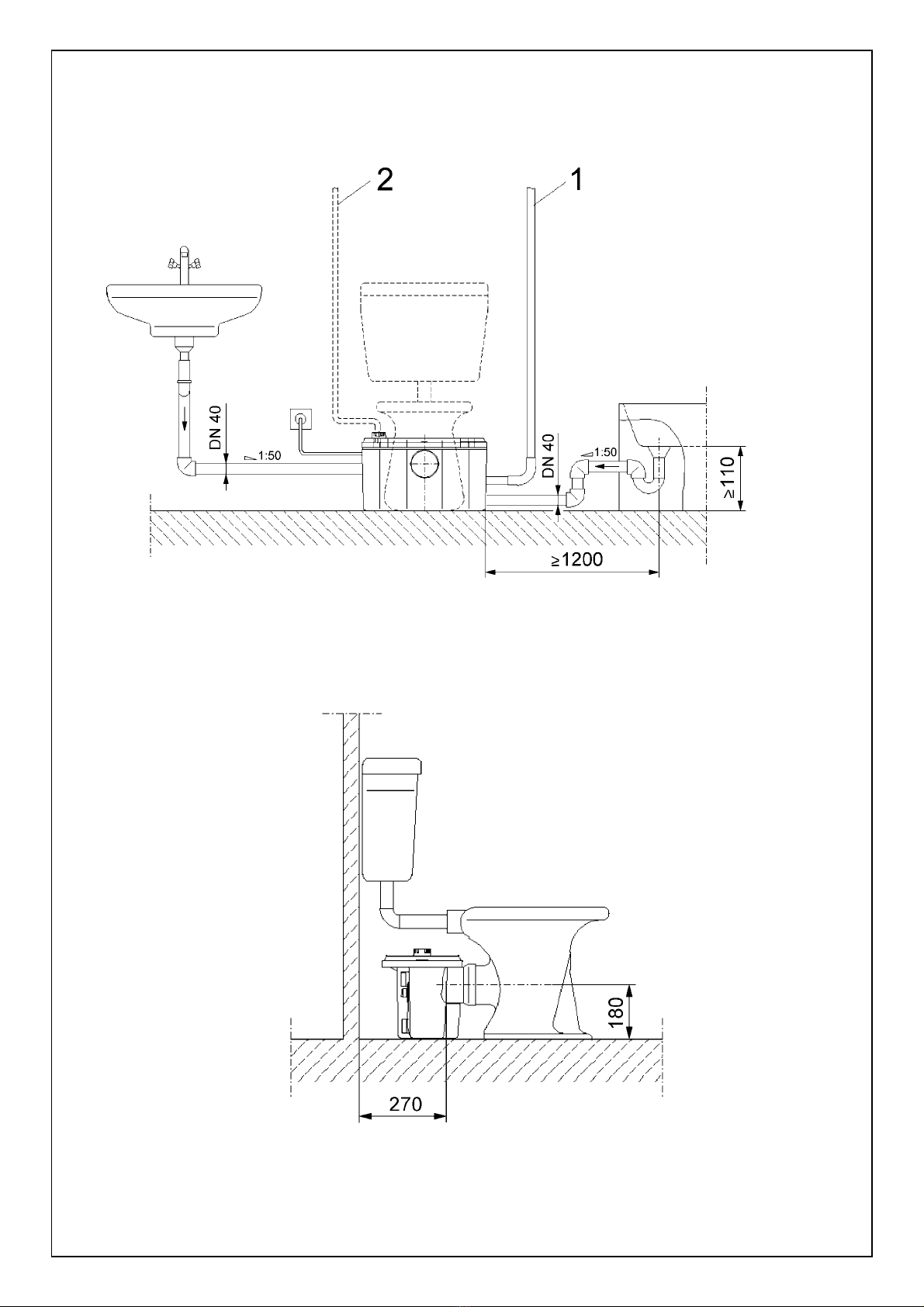
1.1 Verwendungszweck
Automatisch arbeitende Kleinhebeanlage mit Schneid-
werk zur Entsorgung einer Einzeltoilette sowie zu-
sätzlich eines Handwaschbeckens, einer Dusche
und eines Bidet, deren Schmutz-/Abwässer nicht
mit natürlichem Gefälle dem Kanalsystem zugeführt
werden können und deshalb über die Rückstau-
ebene angehoben werden müssen. Die zusätzlich
angeschlossenen Entwässerungsstellen müssen sich
im selben Raum befinden (begrenzte Verwendung
der Kleinhebeanlage). Ferner muß ein weiteres WC
oberhalb der Rückstauebene zur Verfügung stehen.
Die Anlage ist besonders geeignet für die Entsorgung
von Toiletten und Duschen in Kellerräumen.
Für den Einsatz der Anlage sind grundsätzlich die
Normen DIN EN 12050-3, DIN EN 1256 sowie die
DIN 1986-100 einzuhalten.
Die Hebeanlage ist nicht geeignet zur Förderung von
festen Stoffen wie Hygieneartikel, Speisereste, lang-
faserige Stoffe oder von Lösungsmitteln, Fetten und
Öl. Der Anschluß einer Toilette mit Druckspülung ist
nicht zugelassen.
1.2 Anschluß- und Leistungsdaten
– Maximale Fördermenge: 4 m3/h
– Maximale Förderhöhe: 5,7 m
– Max. Fördermedien-Temp.: 35 °C
– Spannung / Frequenz: 1~230 V, 50 Hz
– Aufnahmeleistung: 0,45 kW
– Drehzahl: 2650 1/min
– Nennstrom: 2,1 A
– Betriebsart: S3 28 %, 36 s
– Schutzart: IP 44
– Druckanschluß: DN 25/32
– Zulauf: DN 100 mit
Dichtmanschette
– Nebenzuläufe: 2 x DN 40 nach
DIN 1986 incl.
Blinddeckel und
Manschette
– Entlüftung: 25 mm Außen-Ø
– Abmessungen B x H x T: 511 x 300 x 269 mm
– Nutzvolumen: 12 l
– Gewicht: 7,8 kg
Bei Ersatzteilbestellungen sind sämtliche Daten des
Anlagentypenschildes anzugeben.
2. Sicherheit
Diese Betriebsanleitung enthält grundlegende Hin-
weise, die bei Aufstellung und Betrieb zu beachten
sind. Daher ist diese Betriebsanleitung unbedingt vor
Montage und Inbetriebnahme vom Monteur sowie
dem zuständigen Betreiber zu lesen. Es sind nicht nur
die unter diesem Hauptpunkt Sicherheit aufgeführten
allgemeinen Sicherheitshinweise zu beachten, son-
dern auch die unter den folgenden Hauptpunkten
eingefügten, speziellen Sicherheitshinweise.
5

DEUTSCH
2.1 Kennzeichnung von Hinweisen in der
Betriebsanleitung
Die in dieser Betriebsanleitung enthaltenen Sicher-
heitshinweise, die bei Nichtbeachtung Gefährdungen
für Personen hervorrufen können, sind mit dem all-
gemeinen Gefahrensymbol
bei Warnung vor elektrischer Spannung mit
besonders gekennzeichnet.
Bei Sicherheitshinweisen, deren Nichtbeachtung Ge-
fahren für die Anlage und deren Funktion hervorrufen
können, ist das Wort
eingefügt.
2.2 Personalqualifikation
Das Personal für die Montage muß die entsprechen-
de Qualifikation für diese Arbeiten aufweisen.
2.3 Gefahren bei Nichtbeachtung der
Sicherheitshinweise
Die Nichtbeachtung der Sicherheitshinweise kann
eine Gefährdung für Personen und Anlage zur Folge
haben. Die Nichtbeachtung der Sicherheitshinweise
kann zum Verlust jeglicher Schadenersatzansprüche
führen.
Im einzelnen kann Nichtbeachtung beispielsweise
folgende Gefährdungen nach sich ziehen:
– Versagen wichtiger Funktionen der Anlage,
– Gefährdungen von Personen durch elektrische und
mechanische Einwirkungen,
– Gefährdungen von Personen und Umwelt durch
Nichtbeachtung von Hygienevorschriften für den
Umgang mit Fäkalien.
2.4 Sicherheitshinweise für den Betreiber
Die bestehenden Vorschriften zur Unfallverhütung
sind zu beachten.
Gefährdungen durch elektrische Energie sind auszu-
schließen. Vorschriften des VDE und der örtlichen
Energieversorgungsunternehmen beachten.
Der beigelegte Warnaufkleber muß gut sichtbar auf
dem Toilettendeckel angebracht werden (ggfs. An-
bringung im unmittelbaren Sichtbereich der Toilette).
2.5 Sicherheitshinweise für Inspektions- und
Montagearbeiten
Der Betreiber hat dafür zu sorgen, daß alle Inspek-
tions- und Montagearbeiten von autorisiertem und
qualifiziertem Fachpersonal ausgeführt werden, das
sich durch eingehendes Studium der Betriebsanlei-
tung ausreichend informiert hat.
Grundsätzlich dürfen Arbeiten an der Anlage nur im
Stillstand durchgeführt werden.
2.6 Eigenmächtiger Umbau und
Ersatzteilherstellung
Veränderungen der Anlage sind nur nach Absprache
mit dem Hersteller zulässig. Originalersatzteile und
vom Hersteller autorisiertes Zubehör dienen der
Sicherheit. Die Verwendung anderer Teile kann die
Haftung für die daraus entstehenden Folgen auf-
heben.
2.7 Unzulässige Betriebsweisen
Die Betriebssicherheit der gelieferten Anlage ist nur
bei bestimmungsmäßiger Verwendung entsprechend
Abschnitt 1 der Betriebsanleitung gewährleistet. Die
im Katalog/Datenblatt angegebenen Grenzwerte
dürfen auf keinen Fall über- oder unterschritten
werden.
3. Transport und
Zwischenlagerung
– Beim Transport ist darauf zu achten, daß die An-
lage keinen Stoßbelastungen ausgesetzt wird.
– Die Anlage ist trocken und frostsicher zu lagern.
4. Beschreibung des
Erzeugnisses
4.1 Beschreibung der Anlage
Die automatisch arbeitende Kleinhebeanlage (Bild 1)
besteht aus einem gas- und wasserdichten Sammel-
tank aus Kunststoff, der direkt hinter einer boden-
stehenden Toilette mit horizontalem Abgangstutzen
aufgestellt wird (DIN EN 37). Die Abdichtung des
Zulaufes (Bild 1, Pos.1) erfolgt mit einer selbstdich-
tenden Manschette.
6
ACHTUNG !

DEUTSCH
Die Anschlüsse (Bild 1, Pos. 2) für 2 zusätzliche
Entwässerungsstellen sowie für die Druckleitung
(Bild 1, Pos. 3) befinden sich auf der Rückseite des
Behälters. Der hinter der Anlage verfügbare Platz
ermöglicht eine einfache Rohrführung. Dadurch las-
sen sich die zusätzlichen Zuläufe und die Druck-
leitung von beiden Seiten anschließen.
Die im Behälter eingebaute Pumpe (Bild 2, Pos. 1)
ist mit oben liegendem und leicht zugänglichen
Schneidwerk (Bild 2, Pos. 2) ausgestattet. Die Dick-
stoffe werden soweit zerkleinert, daß sie sicher durch
Pumpe und Druckleitung (Bild 2, Pos. 3) gefördert
werden können.
Die Motorwicklung ist mit einer Überlastsicherung
geschützt, die den Motor bei übermäßiger Bean-
spruchung automatisch abschaltet und nach Abküh-
lung automatisch wieder einschaltet.
Der eingebaute Staudruckschalter (Bild 2, Pos. 4)
schaltet die Anlage niveauabhängig ein und aus.
Die Be- und Entlüftung erfolgt durch den in der An-
lage integrierten Aktivkohlefilter (Bild 2, Pos. 5) direkt
in den Aufstellungsraum oder über eine separat an-
zuschließende Entlüftungsleitung über Dach. Um zu
verhindern, daß bei einem Ausfall der Pumpe und
steigendem Flüssigkeitsstand der Sammeltank
durch den Aktivkohlefilter überläuft, ist eine zusätz-
liche Rückschlagklappe (Bild 2, Pos. 6) eingebaut.
Der Abflußanschluß enthält ebenfalls eine Rück-
schlagklappe (Bild 2, Pos. 7).
4.2 Lieferumfang
– Kleinhebeanlage
– Schlauchanschluß-Set
– 1 Rückschlagklappe für Zulauf DN 40
– 2 Blindverschlüsse für DN 40 (liegen lose bei)
– Warnaufkleber
– Einbau- und Betriebsanleitung
5. Aufstellung/Einbau
5.1 Montage
– Die Anlage ist in einem frostfreien Raum aufzu-
stellen.
– Die Aufstellungsfläche muß waagerecht und plan sein.
– Die Hebeanlage und elektrischer Anschluß (Netz-
stecker) müssen für Wartungsarbeiten auch nach
der Montage zugänglich bleiben.
– Abdeckhaube (Bild 2, Pos. 8) durch Betätigen
des Drehstiftes (Bild 2, Pos. Z) und Drücken der
3 Schnapphaken (seitlich und vorne) abnehmen,
– Die Hebeanlage wird unmittelbar an das Toiletten-
becken mit horizontalem Abgangsstutzen (nach
DIN EN 37) angeschlossen.
– Die weiteren Entwässerungsstellen (z. B. Hand-
waschbecken, Bidet oder Dusche) werden an
die zusätzlichen Zuläufe angeschlossen. Dann die
Überwurfmutter, den Druckring und die vorhandene
Winkelmanschette über die Zulaufleitung (Außen-Ø
40 mm, handelsübliches PVC-Rohr) schieben.
Das PVC-Rohr in den Zulaufstutzen schieben und
die Überwurfmutter fest auf den Zulaufstutzen
schrauben.
Die nicht gebrauchten Zulauföffnungen müssen mit
den mitgelieferten Verschlußkappen verschlossen
werden:
– Druckring auf die Verschlußkappe schieben,
– Dichtung (Querschnittsform: dreieckig) mit der
breiten Kante zum Druckring weisend aufschieben,
– Verschlußkappe in die Überwurfmutter legen und
auf die Zulauföffnung schrauben.
Die seitlichen zusätzlichen Zuläufe
(DN 40) müssen oberhalb des
höchstmöglichen Wasserspiegels
(180 mm) liegen. Deshalb muß das
Aufstellungsniveau (Sohle) der
Duschtasse mindestens 180 mm
höher liegen als das Aufstellungs-
niveau der Kleinhebeanlage (Bild 3).
Unter Verwendung einer Viega-
domoplex-Ablaufgarnitur kann die
Höhe der Duschunterkante bis auf
110 mm über der Aufstellebene
reduziert werden, wenn der Abstand
zwischen der Hebeanlage und Dusche
gleich oder größer 1.200 mm ist.
– Die Rückschlagklappe (Bild 4) wird in die untere
Zulauföffnung bis zum Anschlag so eingeschoben,
daß die Klappe sich zum Behälter öffnen läßt.
Dann, wie oben beschrieben, die Zulaufleitung ein-
schieben (Verwendung der Klappe in Deutschland
nicht zulässig.).
– Druckschlauch auf die gewünschte Länge kürzen,
in der gewünschten Position auf den Schlauch-
stutzen der Anlage schieben und mit der
Schlauchschelle befestigen.
– Das konische Ende des Druckschlauches so tief
wie möglich auf die bauseits zu erstellende Druck-
leitung (DN 25 oder DN 32) schieben und mit einer
Schlauchschelle gegen Abrutschen sichern.
7
ACHTUNG !

DEUTSCH
– In die Druckleitung wird der Einbau einer Absperr-
armatur empfohlen. Sie muß für fäkalienhaltiges
Schmutzwasser geeignet sein und ist bauseits bei-
zustellen.
– Druckleitung (Bild 3, Pos. 1, Mindest-Ø DN 25)
steigend an die Sammelleitung anschließen.
– Soll die Druckleitung horizontal verlaufen, muß sie
nach Austritt aus dem Gerät mit einer Schleife ver-
legt werden.
– Abdeckhaube aufdrücken.
– Zum Schutz gegen evtl. Rückstau aus dem öffent-
lichen Kanal ist die Druckleitung als „Rohrschleife“
auszubilden. Sie muß über der örtlich festgelegten
Rückstauebene (meist Straßenniveau) liegen.
– Soll die Entlüftung nicht durch den im Gerät inte-
grierten Aktivkohlefilter erfolgen, sondern durch
eine Entlüftungsleitung über Dach, so ist die
Abdeckung (Bild 2, Pos. 9) über der Entlüftung zu
entfernen und die Entlüftungsleitung (Bild 3, Pos. 2,
Innen-Ø 25 mm, handelsübliches PVC-Rohr) über
ein flexibles Schlauchstück auf den Stutzen zu
schieben. Der Aktivkohlefilter (Bild 2, Pos. 5) kann
entfernt werden.
– Der mitgelieferte Warnaufkleber (Bild 5) muß gut
sichtbar auf dem Toilettendeckel angebracht wer-
den (ggfs. Anbringung im unmittelbaren Sicht-
bereich der Toilette).
5.2 Elektrischer Anschluß
Die Installation der Steckdose ist von
einem beim örtlichen EVU zugelassenen
Elektroinstallateur und entsprechend den
geltenden VDE-Vorschriften auszuführen.
Wenn die Anschlußleitung dieser Anlage
beschädigt ist, muss sie durch den Kun-
dendienst oder eine ähnlich qualifizierte
Person ersetzt werden.
– Stromart und Spannung des Netzanschlusses
müssen den Angaben auf dem Typenschild der an-
zuschließenden Anlage entsprechen,
– Anlage vorschriftsmäßig erden,
– Netzseitige Absicherung: 10 A, träge.
6. Inbetriebnahme
– Schukostecker einstecken,
– Toilettenspülung bei Erstinbetriebnahme 2-mal
betätigen,
– Alle Rohrverbindungen auf Dichtigkeit kontrollieren.
Evtl. Schlauchschellen nachziehen,
– Spülkasten der Toilette so einstellen, daß das Spül-
volumen von 6 l Wasser nicht unterschritten wird.
7. Wartung
Langfristig wird die Betriebssicherheit erhöht, wenn
einwandfreie Funktion und ruhiger Lauf der Pumpe
kontrolliert werden.
Bei regelmäßigem Gebrauch reinigt sich die Anlage
selbst. Selten benutzte Anlagen sollten von Zeit zu
Zeit wie folgt auch innen gereinigt werden:
Netzstecker ziehen. Ein mildes Reinigungsmittel in
das WC-Becken geben und Spülung betätigen.
Nach ca. 5 Min. Einwirkzeit den Stecker wieder ein-
stecken, Spülung betätigen, Anlage abpumpen las-
sen und danach nochmals nachspülen.
7.1 Wartung und Pflege des Gerätes (Bild 2)
– Spülung 2-3-mal betätigen und Behälter leer-
pumpen,
Vor der Überprüfung der Anlage Netz-
stecker ziehen!
– Abdeckhaube (Bild 2, Pos. 8) durch Betätigen
des Drehstiftes (Bild 2, Pos. Z) und Drücken der
3 Schnapphaken (seitlich und vorne) abnehmen,
Verletzungs- und Infektionsgefahr am
Schneidmesser! Schutzhandschuhe be-
nutzen!
– Bei Bedarf Siebkorb herausnehmen und ggfs. alle
Fremdkörper aus dem Gerät entfernen,
– Verunreinigungen an den Behälterwänden besei-
tigen,
– Entlüftungsleitung bzw. Entlüftungsventil reinigen,
Aktivkohlefilter erneuern,
– Montage in umgekehrter Reihenfolge,
– Bei der Verwendung von Dauerreinigern auf deren
sichere Fixierung am WC achten.
7.2 Demontage der Pumpe (Bild 2)
Spülung, Öffnen des Gerätes sowie Beachtung der
Warnhinweise wie in 7.1 beschrieben,
– 3 Schrauben der Motorbefestigung lösen (Bild 2,
Pos. 11),
– Obere Schlauchschelle (Bild 2, Pos. 12) des
Abflußanschlusses lösen,
– Verschraubung des Entlüftungsröhrchens (Bild 2,
Pos. 13) an der Behälterwand lösen und Entlüf-
tungsröhrchen abziehen,
8

DEUTSCH
– PG-Verschraubung des Anschlußkabels (Bild 2,
Pos. 14) an der Behälterwand lösen und Kabel zur
Behälterinnenseite durchziehen,
– Falls die Pumpe ganz aus dem Behälter herausge-
nommen werden soll, den Stecker des elektrischen
Anschlusses abschrauben und das Kabel aus der
PG-Verschraubung herausziehen,
– Pumpe mit Staudruckschalter und Elektroanschluß
herausnehmen,
– Reinigen des Schneidmessers, des Laufrades und
der Öffnung des Staudruckschalters,
– Montage der Bauteile in umgekehrter Reihenfolge
durchführen,
– Probelauf durchführen.
Vor dem Transport einer benutzten
KH 32-0,4, ist die Anlage aus hygie-
nischen Gründen zu entleeren und zu
reinigen. Außerdem müssen alle mit
infektiösem Material in Berührung gekommenen Teile
desinfiziert (Sprühdesinfektion) werden. Die Teile
müssen in reißfesten, ausreichend großen Kunst-
stoffsäcken dicht verschlossen und auslaufsicher
verpackt werden und sind mit bekannten Spedi-
teuren unverzüglich einzusenden.
9
Störung Ursache Abhilfe
Motor läuft nicht Netzspannung fehlt Spannung u. Sicherung überprüfen
Schneidmesser blockiert, Haube demontieren, Motorwelle im Uhrzeigersinn frei-
Überlastschalter hat aus- drehen, Schneidmesser reinigen. Im Wiederholungs-
gelöst fall Kundendienst einschalten.
Motor überlastet, Überlast- bei wiederholtem Auftreten Kundendienst einschalten
sicherung hat ausgelöst
Staudruckschalter defekt Kundendienst einschalten
Motor defekt Kundendienst einschalten
Motor läuft, Druckleitung verstopft oder Verstopfung bzw. Knicke beseitigen,
Pumpe fördert nicht geknickt Probelauf durchführen
Anlagenentlüftung Entlüftungsrohr abziehen und reinigen bzw. Aktiv-
verstopft kohlefilter erneuern
Pumpe läuft in Entlüftung verstopft Entlüftung reinigen
kurzen Intervallen Rückschlagklappe undicht Säubern bzw. erneuern
Spülkastenventil hängt fest Funktion wiederherstellen
Motor dreht mit gro- Fremdkörper im Gerät Motor ausbauen und reinigen, ggfs. Kundendienst
ßen Laufgeräuschen einschalten
8. Störungen, Ursachen und Beseitigung
Läßt sich die Betriebsstörung nicht beheben, wenden Sie sich bitte an Ihren Sanitär- und Heizungs-
fachhandwerker oder an den Wilo-Kundendienst.
Technische Änderungen vorbehalten!

ENGLISH
Information on operation
Dear customer,
In this chapter we would like to explain how the
ready-installed unit functions and operates.
However, we would also encourage you to read the
safety instructions described in the complete manual
for assembly and operation carefully.
Repairs on this unit should only be carried out by an
expert or by Wilo customer services.
The unit’s functions are all automatic. It is not neces-
sary to service the unit. Cleaning, if required, should
be carried out in accordance with the following in-
structions.
Cleaning
The unit cleans itself during regular use. Only seldom-
used units should be cleaned every three months
(also internally) as follows:
Pull the plug out of the socket. Pour a mild cleaning
agent into the toilet bowl and flush. After approxi-
mately 5 mins, plug the plug back in. Flush until the
pump switches on and pumps out the cistern. Then
flush again.
In the long term, the level of safety is increased when
the pump’s functioning and quiet running are checked
by a technical operator.
1. General Information
Installation and commissioning
by qualified personnel only!
1.1 Uses
An automatic mini lifting unit with cutting implement
for the sanitation of individual toilets, hand basins,
showers and bidets, whose dirty or waste water cannot
be transported into the canal system with a natural fall
and must therefore be lifted above the reflux level. The
additional draining points connected to the unit must
be located in the same room (limited use of mini lifting
unit). Another WC must be available above the reflux
level. This unit is particularly suitable for the sanitation
of toilets and showers in cellars.
The norm DIN EN 12050-3, DIN EN 12056 and
DIN 1986-100 should be adhered to when installing
the unit.
The lifting unit is not suitable for transporting solid
material such as hygiene articles, food leftovers,
long-fibred materials or solvents, fats and oil. It is
not permitted to connect the unit to a toilet with a
flushing valve.
1.2 Technical description
– Maximum transporting
capacity: 4 m3/h
– Maximum head: 5.7 m
– Max. flow medium
temperature: 35 °C
– Voltage/frequency: 1~230 V, 50 Hz
– Power input: 0.45 kW
– Speed: 2650 1/min
– Nominal current: 2.1 A
– Type of operation: S3 28 %, 36 s
– Type of protection: IP 44
– Discharge connection: DN 25/32
– Inlet connection: DN 100 with seal collar
– Additional supply: 2 x DN 40 in
accordance with
DIN 1986 incl. blind
cover and collar
– Ventilation: 25 mm outer diameter
– Dimensions W x H x D: 511 x 300 x 269 mm
– Useful volume: 12 l
– Weight: 7.8 kg
When ordering spare parts, all details on the unit’s
rating plate should be given.
2. Safety precautions
These instructions contain important information
which must be followed when installing and operat-
ing the pump. It is therefore imperative that they be
read by both the installer and the operator before the
pump is installed or started up. Both the general
safety instructions in the ‘Safety precautions’ section
and those in subsequent sections indicated by danger
symbols should be carefully observed.
2.1 Danger symbols used in these
operating instructions
Safety precautions in these operating instructions
which, if not followed, could cause personal injury are
10

ENGLISH
indicated by the symbol:
Safety precautions warning of danger due to electri-
city are indicated by the symbol:
Safety precautions which, if not followed, could
damage the pump or installation and cause it to mal-
function are indicated by the word:
2.2 Qualified Personnel
The personnel installing the pump must be appro-
priately qualified to carry out this work.
2.3 Risks incurred by failure to comply
with the safety precautions
Failure to comply with the safety precautions could
result in personal injury or damage to the pump or
installation. Failure to comply with the safety precau-
tions could also invalidate any claim for damages.
In particular, failure to comply with these safety pre-
cautions could give rise, for example, to the following
risks:
– the failure of important parts of the pump or installation,
– personal injury due to electrical and mechanical
causes,
– personal injury and damage to the environment due
to failure to comply with hygiene regulations when
handling sewage.
2.4 Safety precautions for the operator
Existing regulations for the prevention of accidents
must be followed.
To prevent the risk of electric shock or electrocution,
VDE regulations and those of the local supply com-
pany must be followed.
The warning stickers included in the delivery must be
attached in a visible position on the toilet cover (in
direct view of the toilet, if necessary).
2.5 Safety precautions for inspection
and installation
The operator must ensure that all inspection and
installation work is carried out by authorised and
qualified specialists who have carefully studied these
instructions. In principle, work on the unit may only
be carried out after it has been brought to a stand-
still.
2.6 Unauthorised alterations and manufacture
of spare parts
Alterations to the pump or installation may only be
carried out with the manufacturer’s consent. The use
of original spare parts and accessories authorised by
the manufacturer will ensure safety. The use of any
other parts may invalidate claims invoking the liability
of the manufacturer for any consequences.
2.7 Improper use
The operational safety of the unit supplied can only
be guaranteed if it is used in accordance with para-
graph 1 of the operating instructions. Under no cir-
cumstances may the limits exceed or fall short of
those given in the catalogue or data sheet.
3. Transport and storage
– Care should be taken during transport that the unit
is not damaged by impact against other objects.
– The unit should be stored in a dry, frost-free place.
4. Description of the product
4.1 Description of the unit
The automatic mini lifting unit (fig. 1) is a plastic gas-
proof and waterproof collector tank which is placed
directly behind a pedestal type toilet with a horizon-
tal waste connection pipe (DIN EN 37).
The supply channel is sealed with a self-sealing collar
(see fig. 1, pos. 1).
The connections (fig. 1, pos. 2) for two additional
drainage points and also for the compressed air
piping (fig. 1, pos. 3) are located at the back of the
cistern. The space behind the unit makes it easy to
guide the pipes. In this way, the additional supply
channels and the compressed air piping can be
connected from both sides.
The pump which is built into the cistern (fig. 2, pos. 1)
is equipped with a cutting tool (fig. 2, pos. 2) which
lies above it and is easily accessible. The thick matter
is broken down enough that it can be transported
through the pump and compressed air piping (fig. 2,
pos. 3).
11
ATTENTION!

ENGLISH
The motor coil is protected by an overload safety
device which automatically switches off the motor if
exposed to an above-average level of stress. After
the motor has cooled down, it is automatically
switched back on.
The in-built booster relay (fig. 2, pos. 4) switches the
unit on and off, depending on the level.
The activated carbon filter integrated into the unit
(fig. 2, pos. 5) enables airing and ventilation to take
place directly in the installation room or by means of
an aeration pipe on the roof which should be connec-
ted separately. In order to prevent the collection tank
from overflowing through the activated carbon filter in
the event of pump failure and an increase in the level
of liquid, an additional flap trap (fig. 2, pos. 6) has
been added. The drain connection also contains a
flap trap (fig. 2, pos. 7).
4.2 Products delivered
– mini lifting unit
– hose connection set
– 1 inlet checkvalue DN 40
– 2 welches for DN 40 (enclosed)
– warning sticker
– instructions for assembly and operation
5. Assembly/Installation
5.1 Assembly
– The unit should be installed in a frost-free room.
– The assembly area must be horizontal and flat.
– The lifting unit and the electrical connection (plug)
must remain accessible for maintenance even after
assembly.
– Remove covering cap (fig. 2, pos. 8) using the
tommy bar (fig. 2, pos. Z) and pressing the 3 spring
hooks (at side and front).
– The lifting unit is connected directly to the toilet
bowl with a horizontal waste connection pipe (in
accordance with DIN EN 37).
– The remaining drainage areas (e.g. wash basin,
bidet or shower) are connected to the additional
supply channels. The union nut, pressure ring and
existing angle collar should then be pushed over
the supply channel (outer-Ø 40 mm, commercially
available PVC pipe).
Push the PVC pipe into the supply channel connec-
tion pipe and screw the union nut tightly on to the
inlet connection pipe.
The unused inlet opening must be locked with the
cowl provided:
– Push the pressure ring on to the cowl
– Slide on the seal (cross section form: three-sided)
with the wide edge pointing to the pressure ring
– Lay the cowl in the union nut and screw on to the
supply channel opening.
The additional side supply channels
(DN 40) must be positioned above the
highest possible water lever (180 mm).
For this reason the construction level
(base) of the shower basin must lie
at least 180 mm higher than the
construction level of the mini lifting
unit (fig. 3). The shower surface may
be reduced to 110 mm above the
construction level when installing
Viega-domoplex discharge fittings,
when the distance between the lifting
unit and the shower is equal to or
larger than 1,200 mm.
– The flap trap (fig. 4) is pushed into the lower supply
channel opening as far as the limit stop in such a
way that the trap is open to the cistern. Then push
in the supply pipe as described above (use of trap
not permissible in Germany).
– Shorten the pressure hose to the desired length,
push it into the desired position on the hose
connection pieces and secure with the clamp.
– Push the conical end of the pressure hose as far as
possible onto the pressure pipeline (DN 25 or DN 32)
which should be connected on site and secure
against sliding with a clamp.
– It is recommended that a shut-off device be instal-
led in the pressure pipeline. It must be suitable for
waste water containing sewage and should be
connected on site.
– Connect pressure pipeline (fig. 3, pos. 1, minimum-
Ø DN 25) upwardly onto the collector pipe.
– If the pressure pipeline runs horizontally off centre, it
must be laid with a loop when it comes out of the unit.
– Press on covering cap.
– In order to protect against possible reflux out of the
public channel, the pressure pipeline should be
formed as a “pipe loop”. It must be placed over the
locally set reflux level (usually street level).
– If ventilation takes place through a vent connection
in the roof rather than through the activated carbon
filter which is integrated into the unit, the cap
12
ATTENTION!

ENGLISH
(fig. 2, pos. 9) should be removed from the ventila-
tion and the vent connection (fig. 3, pos. 2, inner-
Ø 25 mm, commercially available PVC pipe) and
should be pushed by a flexible piece of hose on to
the support. The activated carbon filter (fig. 2, pos. 5)
can be removed.
– The warning sticker included in the delivery (fig. 5)
must be adhered in a visible position on the toilet
cover (if necessary, in direct view of the toilet).
5.2 Electrical installation
–Electrical work must be carried out by a
qualified and licensed electrician in strict
compliance with local regulations. If the
units power cable is damaged it must be
replaced by the customer service or a
similar qualified person.
– The mains current and voltage must comply with the
data on the rating plate of the unit to be connected.
– Earthing must be carried out according to regulations.
– Line side fuse protection: 10 A, neutral.
6. Starting up
– Plug in shock-proof plug
– Flush toilet twice during initial start-up
– Monitor all pipe connections for leakages. If neces-
sary, tighten hose clamps.
– Adjust the cistern so that the flushing volume does
not fall below 6 l of water.
7. Maintenance
The operation reliability is increased in the long run
when the perfect functioning and quiet running of the
pump are monitored.
The unit cleans itself when used regularly. Seldom-
used units should be cleaned internally now and
again as follows:
Pull out the plug. Pour a mild cleaning agent into the
toilet bowl and flush. After approximately 5 mins, plug
in the unit, flush, leave the unit to pump and then flush
again.
7.1 Maintenance and care of unit (fig. 2)
– Flush 2–3 times and pump the cistern empty
Pull out the plug before checking the
unit!
– Remove covering cap (fig. 2, pos. 8) using the
tommy bar (fig. 2, pos. Z) and pressing the 3 snap
hooks (side and front).
Danger of injury and infection from
cutting instruments! Use protective
gloves!
– If necessary, remove strainer basket and all foreign
bodies from the unit.
– Eliminate impurities on the cistern walls.
– Clean vent pipe or ventilating valve, renew acti-
vated carbon filter.
– Assemble in opposite order
– When using toilet freshners, make sure that they
are safely secured to the WC.
7.2 Dismantling the pump (fig. 2)
Flushing, opening the unit and observing warning
symbols as described in 7.1
– Unscrew the 3 fixing screws at the motor flange
(fig. 2, pos. 11).
– Unscrew the upper hose clamp (fig. 2, pos. 12) on
the discharge connection.
– Unscrew the screw of the ventilation pipe (fig. 2,
pos. 13) on the cistern wall and pull off the ventila-
tion pipe.
– Unscrew the connection cable PG screw joint
(fig. 2, pos. 14) on the tank wall and pull the cable
through to the inside of the cistern.
– If the pump is to be removed from the tank com-
pletely, screw off the electric plug and take the
cable out of the PG screw joint.
– Take out the pump with booster relay and electri-
cal connection.
– Clean the cutting instrument, impeller and the
opening of the booster relay.
– Assemble the components in the opposite order.
– Carry out test run.
For reasons of hygiene, used KH 32–0.4
units should be emptied and cleaned
before transportation. Furthermore, all
components which come into contact
with infectious material should be disinfected
(spray disinfected). The components must be
tightly sealed in sufficiently large, tear-resistant
plastic sacks and packed so that they do not leak.
They should be disposed of by reliable haulage
contractors immediately.
13

ENGLISH
14
Fault Cause Remedy
Motor does not run Lack of voltage Check voltage and fuses
Cutting implement blocked, Dismantle cap, rotate motor shaft clockwise freely,
overload switch clean cutting implement. In the event of reoccurrence,
disengaged contact customer services.
motor overloaded, overload If the event of reoccurrence, contact customer
switch disengaged services.
booster relay defect contact customer services
motor defect contact customer services
motor runs, pump pressure pipeline blocked remove blocking or buckling
does not function or buckled carry out test run
unit ventilation blocked remove and clean ventilation pipe or replace activated
carbon filter
pump runs in short ventilation blocked clean ventilation
intervals leak in flap trap clean or replace
cistern ventilation stops reproduce function
motor makes loud foreign bodies in unit Dismantle motor and clean. If necessary, contact
noises when rotating customer services.
8. Faults, causes and remedies
If the fault cannot be remedied, please contact your local plumbing and heating specialist or Wilo
customer services.
Subject to technical alterations!

FRANÇAIS
Conseil d’utilisation
Chers clients,
Dans ce chapitre, nous voudrions vous expliquer les
fonctions de l’installation prête au raccordement.
Nous vous prions de lire attentivement les instruc-
tions de sécurité contenues dans la notice de mon-
tage et de mise en service.
Nous vous conseillons de confier les réparations
de l’appareil à un fournisseur spécialisé ou au SAV
Wilo.
L’installation est automatique. Il n’est pas nécessaire
de la piloter. En cas de nécessité, il faut procéder au
nettoyage de l’appareil comme suit.
Nettoyage
L’appareil utilisé régulièrement est auto-nettoyant.
Seules les installations peu utilisées devront être
nettoyées tous les trimestres comme suit:
Débrancher l’appareil. Verser un produit de nettoyage
non agressif dans la cuvette des toilettes et actionner
la chasse d’eau. Laisser agir 5 mn et rebrancher
l’appareil. Actionner la chasse d’eau jusqu’à ce que
la pompe s’enclenche et que le réservoir se vide. Puis
rincer de nouveau.
Le fonctionnement de l’installation s’améliore en
cours d’usage, lorsqu’elle est utilisée correctement.
1. Généralités
Montage et mise en service uniquement
par du personnel qualifié!
1.1 Application
Mini station de relevage automatique avec broyeur
pour l’assainissement des toilettes, mais aussi d’un
lavabo, d’une douche et d’un bidet, dont les eaux
usées ne peuvent pas être évacuées naturellement
vers la canalisation, et doivent être relevées vers le
niveau de refoulement. Les autres appareils sanitaires
doivent se trouver dans la même pièce (d’où rayon
d’utilisation de la station limité). Il faut absolument
que d’autres toilettes, situées au dessus du niveau
de refoulement, soient accessibles. La station est
particulièrement adaptée pour l’assainissement de
toilettes et de douches situées en sous-sol.
Observer les normes DIN EN 12050-3, DIN EN
12056 et DIN 1986-100.
La station n’est pas adaptée pour véhiculer des rési-
dus solides tels que des protections hygiéniques,
des restes de repas, des résidus à fibres longues ou
des solutions, des graisses ou de l’huile. Elle ne doit
pas être raccordée à des toilettes avec robinet de
chasse.
1.2 Raccordement et puissance
– Débit maxi: 4 m3/h
– Hauteur manométrique maxi: 5,7 m
– Température du fluide maxi: 35 °C
– Nature du courant: Mono 230 V, 50 Hz
– Puissance absorbée: 0,45 kW
– Vitesse: 2650 tr/min
– Intensité nominale: 2,1 A
– Niveau d’utilisation: S3 28 %, 36 s
– Protection: IP 44
– Diamètre de raccordement: DN 25/32
– Aspiration: DN 100 avec
manchette
d’étanchéité
– Aspirations annexes: 2 x DN 40 selon
DIN 1986 ainsi que
bouchon et
manchettes
– Ventilation: 25 mm dia. externe
– Volume utile: 12 litres
– Encombrements B x H x T: 511 x 300 x 269 mm
– Poids: 7,8 kg
Lors de la commande de tout accessoire, indiquer les
caractéristiques de la plaque signalétique.
2. Sécurité
La présente notice contient les instructions à res-
pecter lors du montage et de la mise en service. C’est
pourquoi elle devra être lue attentivement par le mon-
teur et l’utilisateur. Il y a lieu d’observer non seulement
ce point principal mais aussi les prescriptions de
sécurité spécifiques abordées dans les points
suivants.
2.1 Signalisation des consignes de la notice
Les prescriptions de sécurité contenues dans cette
notice pour mettre en garde les personnes sont
symbolisées par:
15
Other manuals for Wilo-DrainLift KH 32-0,4
1
Table of contents
Languages:
Other Wilo Plumbing Product manuals
Popular Plumbing Product manuals by other brands

Lamona
Lamona Arroscia manual

Fontana Showers
Fontana Showers FS145112 installation instructions

Signature Hardware
Signature Hardware SHWE2020 quick start guide

American Standard
American Standard Colony Soft 3875.220 installation instructions

Krowne
Krowne SILVER Series installation manual

Laufen
Laufen ILBAGNOALESSI One 8.1197.2 Installation