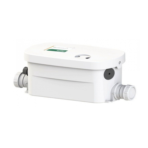
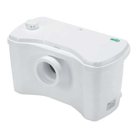
Wilo HiSewlift 3 Series User manual

4 194 364-Ed.01 / 2014-11-Wilo
Wilo-HiSewlift 3
Pioneering for You
de Einbau- und Betriebsanleitung
en Installation and operating instructions
fr Notice de montage et de mise en service
nl Inbouw- en bedieningsvoorschriften
es Instrucciones de instalación y funcionamiento
it Istruzioni di montaggio, uso e manutenzione
pt Manual de Instalação e funcionamento
tr Montajvekullanmakılavuzu
el Οδηγίεςεγκατάστασηςκαιλειτουργίας
sv Monterings- och skötselanvisning
pl Instrukcjamontażuiobsługi
ru Инструкцияпомонтажуиэксплуатации
uk Iнструкціязмонтажутаексплуатації
ro Instrucţiunidemontajşiexploatare
bg Инструкциязамонтажиексплоатация
zh 安装及操作说明

Fig. 1
2

Fig. 2
3
HiSewlift3-15
HiSewlift3-35
261,5
261,5
511
622
243
243
184
184
317
317
138
138
184
184
185,5185,5
Ø110
Ø110
Ø110Ø110
Ø40
Ø40
Ø32
Ø32
Ø28
Ø28
Ø22
Ø22
53,5
53,5
347,5
347,5
98
65
1 2 3 4
7

Fig. 3
4
HiSewlift3-I35
355
282,5
184
184
39
369,5
470 74,2
53
Ø40
Ø40
Ø110
Ø32
39
512
103,5 163,5
148,5
Ø28
Ø22
765
1 2 3 4
8

Fig. 4
Fig. 5
5
>2%
>2%

Fig. 6
6
1
2
x
x
x
x
x
✓
✓
✓✓
✓
✓✓

Fig. 7
7
1
2
3
4

Fig.8
8
1
3
5
7
2
4
6
8

Fig. 9
9
1
3
2
4

10

22
English
1 General
1.1 About this document
The language of the original operating instructions is French. All other languages
of these instructions are translations of the original operating instructions.
These installation and operating instructions are an integral part of the product.
They must be kept readily available at the place where the product is installed.
Strict adherence to these instructions is a precondition for the proper use and
correct operation of the product.
These installation and operating instructions correspond to the relevant version of
the product and the underlying safety standards valid at the time of going to print.
EC declaration of conformity:
A copy of the EC declaration of conformity is a component of these operating
instructions.
If a technical modification is made on the designs named there without our
agreement, this declaration loses its validity.
2 Safety
These installation and operating instructions contain important information
which must be adhered to during installation, operation and maintenance. For this
reason, these instructions must, without fail, be read by the service technician and
the responsible specialist/operator before installation and commissioning.
It is not only the general safety instructions listed under the main point “safety”
that must be adhered to but also the special safety instructions with danger
symbols included under the following main points.
2.1 Symbols and signal words in the operating instructions
Symbols:
General danger symbol
Danger due to electrical voltage
NOTE
Signal words:
DANGER!
Acutely dangerous situation.
Non-observance results in death or the most serious of injuries.
WARNING!
The user can suffer (serious) injuries. ‘Warning’ implies that (serious) injury to
persons is probable if this information is disregarded.
ATTENTION!
There is a risk of damaging the product/unit. ‘Caution’ implies that damage to the
product is likely if this information is disregarded.
09/2014

23
English
WILO SE
NOTE: Useful information on handling the product. It draws attention to possible
problems.
Information that appears directly on the product, such as.
• Direction of rotation arrow,
• Marks identifying connections,
• Rating plate,
• Warning stickers,
must be strictly complied with and kept in legible condition.
2.2 Personnel qualifications
The installation, operating and maintenance personnel must have the appropriate
qualifications for this work. Area of responsibility, terms of reference and
monitoring of the personnel are to be ensured by the operator. If the personnel
are not in possession of the necessary knowledge, they are to be trained and
instructed. This can be accomplished if necessary by the manufacturer of the
product at the request of the operator.
2.3 Danger in the event of non-observance of the safety instructions
Non-observance of the safety instructions can result in risk of injury to persons
and damage to the environment and the product/unit. Non-observance of the
safety instructions results in the loss of any claims to damages. In detail, non-
observance can, for example, result in the following risks:
• Danger to persons due to electrical, mechanical and bacteriological factors,
• Damage to the environment due to leakage of hazardous materials,
• Property damage,
• Failure of important product/unit functions,
• Failure of required maintenance and repair procedures.
2.4 Safety consciousness on the job
The existing directives for accident prevention must be adhered to.
Danger from electrical current must be eliminated. Local directives or general
directives [e.g. IEC, VDE etc.] and instructions from local energy supply companies
must be adhered to.
2.5 Safety instructions for the operator
This appliance is not intended for use by persons (including children) with reduced
physical, sensory or mental capabilities, or lack of experience and knowledge,
unless they have been given supervision or instruction concerning use of the
appliance by a person responsible for their safety.
Children should be supervised to ensure that they do not play with the appliance.
• If hot or cold components on the product/the unit lead to hazards, local measures
must be taken to guard them against touching.
• Guards which protect personnel from coming into contact with moving
components (e.g. the coupling) must not be removed while the product is in
operation.

24
English
• Leakages (e.g. from the shaft seals) of hazardous fluids (which are explosive, toxic
or hot) must be led away so that no danger to persons or to the environment
arises. National statutory provisions are to be complied with.
• Danger from electrical current must be eliminated. Local directives or general
directives [e.g. IEC, VDE etc.] and instructions from local energy supply companies
must be adhered to.
2.6 Safety instructions for installation and maintenance work
The operator must ensure that all maintenance and installation work is carried out
by authorised and qualified personnel, who are sufficiently informed from their
own detailed study of the installation and operating instructions. Work on the
product/unit must only be carried out when at a standstill. It is mandatory that
the procedure described in the installation and operating instructions for shutting
down the product/unit be complied with.
Immediately on conclusion of the work, all safety and protective devices must be
put back in position and/or recommissioned.
2.7 Unauthorised modification and manufacture of spare parts
Unauthorised modification and manufacture of spare parts will impair the safety
of the product/personnel and will make void the manufacturer’s declarations
regarding safety. Modifications to the product are only permissible after
consultation with the manufacturer.
Original spare parts and accessories authorised by the manufacturer ensure safety.
The use of other parts will absolve us of liability for consequential events.
2.8 Improper use
The operating safety of the supplied product is only guaranteed for conventional
use in accordance with Section 4 of the operating instructions. The limit values
must on no account fall under or exceed those values specified in the catalogue/
data sheet.
3 Transport and intermediate storage
When you receive the equipment, check that it has not been damaged during
transport. If you notice a fault, take all necessary action with the carrier within the
time allowed.
• Unpack the lifting unit and recycle or dispose of the packaging in an environmen-
tally responsible manner.
• Be sure to check the condition of the product upon delivery.
CAUTION! Storage environment may cause damage!
If the equipment is to be installed at a later date, store it in a dry place and protect
it from impacts and any external stresses (humidity, frost etc.).
Temperature range for transport and storage: -30°C to +60°C.
Handle the system with care so as not to damage the product before installation.
09/2014

25
English
4 Applications
This device is a compact lifting unit designed for draining wastewater coming from
a toilet via horizontal drainage, from a washbasin, from a shower* or from a bidet*.
(*: depending on the model).
This device complies with the standard EN 12050-3 and with the European
standards for electrical safety and electromagnetic compatibility.
DANGER! Risk of explosion!
Do not use this system to lift flammable or explosive liquids.
5 Product information
5.1 Type key (Fig. 1)
WILO SE
Example: HiSewlift 3-I35
HiSewlift Version
HiSewlift: Standard version
3 Product grade
1: Standard
3: Efficient
5: Premium
I Front-wall installation
I: Can be installed in a frame in front of the
wall
3Number of connections + toilet
5Delivery head

5.2 Technical data
5.3 Included in delivery
• Lifting system
• Operating manual
For HiSewlift 3-15: outlet elbow (x1), 3-outlet bushing (x1), clamp 32x55 (x4),
clamp 25x40 (x1), clamp 20x32 (x1), hose (x1), Ty Wrap (x1), clamp 90x110 (x1),
inlet elbow (x1), screw (x2), fixation strip (x2).
For HiSewlift 3-35: outlet elbow (x1), 3-outlet busching (x1), clamp 32x55 (x8),
clamp 25x40 (x1), clamp 20x32 (x1), hose (x1), Ty Wrap (x1), clamp 90x110 (x1),
inlet bushing (x3), lateral inlet bushing (x1), vis(x2), fixation strip(x2).
For HiSewlift 3-I35: outlet elbow (x1), 3 outlet bushing(x1), clamp 32x55 (x4),
clamp 25x40 (x1), clamp 20x32 (x1), inlet bush (x1), lateral inlet plug (x2), screw
(x2), fixation strip(x2).
5.4 Description
HiSewlift 3-15 and HiSewlift 3-35 (Fig. 2)
1 - Bushing
2 - Elbow
3 - 3-outlet bushing
4 - Plug
5 - Fixation strip (x2)
6 - Screw (x2)
7 - Screw clamp (x2 for each part number)
8 - Hose
9 - Ty-Wrap
Hydraulic data HiSewlift 3-15 HiSewlift 3-35 HiSewlift 3-I35
Maximum vertical delivery 5 m 5 m 5 m
Maximum Horizontal delivery 90 m 90 m 90 m
Maximum altitude 1000 m 1000 m 1000 m
DN of suction connection DN40 DN40 DN40
DN of pressure connection DN32-28-22 DN32-28-22 DN32-28-22
Number of connections
1 for toilet + 1 1 for toilet + 3 1 for toilet + 3
Temperature range
Fluid temperature range +5°C to +35°C +5°C to +35°C +5°C to +35°C
Ambient temperature Max. +40°C Max. +40°C Max. +40°C
Electrical data
Motor protection rating IP 44 IP 44 IP 44
Insulation class Class I Class I Class I
Frequency 50 Hz 50 Hz 50 Hz
Voltage 220/240 V 220/240 V 220/240 V
Rated current 1.9 A 1.9 A 1.9 A
26
English
09/2014

27
English
HiSewlift 3-I35 (Fig. 3)
1 - Bushing
2 - Elbow
3 - 3-outlet bushing
4 - Plug
5 - Fixation strip (x2)
6 - Screw (x2)
7 - Foam foot (x4)
8 - Screw clamp (x2 for each part number)
6 Description and function
6.1 Description of the product (see figures)
Compact lifting unit for domestic wastewater which cannot flow naturally into the
sewer or natural outfall.
6.2 Function of the product
Automatic collection and drainage of domestic wastewater.
7 Installation and connections
DANGER! Risk of fatal injury!
Any improper installation or improper electrical connection may have fatal
consequences. Danger from electrical current must be eliminated.
• Installation and electrical connection work must always be carried out by
qualified technical personnel and in accordance with the applicable regulations.
• Comply with accident prevention regulations.
• Follow the instructions of the local energy supply company!
• The comminutor must be in the same room as the toilet and the other sanitary
installations connected.
• The device must be easily accessible for inspection, maintenance and repair.
• The installation and functioning of your device must comply with local regulations
and the standard EN12056-4.
• To make the most of the latest developments for noise reduction included in the
design of this device, it is important to:
- Install the tank so that it is not touching the walls of the room if possible,
- Position the tank on a completely flat surface so as not to impair the function of
the anti-vibration supports,
- Secure the drainage piping correctly, avoiding distances greater than one metre
between fixation points.
• HiSewlift 3-15 and HiSewlift 3-35 (Fig. 4 and 6)
• HiSewlift 3-I35 (Fig. 5 and 6)
WILO SE

7.1 Hydraulic connections
• HiSewlift 3-15 and HiSewlift 3-35 (Fig. 7)
• HiSewlift 3-I35 (Fig. 8)
General connection instructions
• Use flexible, braid-reinforced hose piping or rigid piping.
• The system must not bear the weight of the pipes.
• Seal the piping well using appropriate products.
NOTE: The air cushion in the connection pipe may cause problems with flow and
blockage. To prevent any blockage, the inlet pipe should be purged at its highest
point.
Installing the lifting unit before putting the cover back on the frame facilitates the
installation and inspection of the connections.
Suction connection
• The diameter of the suction pipe must never be less than the port on the system.
7.2 Electrical connection (Fig. 9)
WARNING! Risk of electric shock!
Danger from electrical current must be eliminated.
• Have all electrical work carried out by a qualified electrician only!
• Before any electrical connection is made, the unit must be de-energised
(switched off) and protected against unauthorised restarting.
• To ensure safe installation and operation, the unit must be earthed correctly with
the earth terminals of the power supply.
ATTENTION! risk of damaging the product/unit!
An error in the electrical connection will damage the motor.
The power cable must never touch the piping or the system, and must be kept
away from any moisture.
• Do not switch on the power supply until the electrical connections have been fully
completed.
• When positioning the device, make sure that the mains power plug is accessible.
• The power supply circuit of the device must be earthed (class I) and protected by a
high sensitivity residual-current device (30 mA).
• The connection must be used solely to supply power to the device.
• If the cable of this device is damaged, it must be replaced by the manufacturer or
the manufacturer’s customer service.
• Observe the requirements of the standard applicable in the country of use (in
France, for example: NF C 15-100) governing electrical safety zones in bathrooms.
28
English
09/2014

29
English
8 Commissioning
• Flush the toilet several times. The toilet bowl outlet must be free of leaks.
• Switch on the power supply to the system.
• Check that there are no leaks at the connections to the sanitary devices
connected to the lifting unit.
• Check that the current consumed is less than or equal to the rated current.
9 Maintenance
All maintenance work must be carried out by authorised and qualified
personnel!
WARNING! Risk of electric shock!
Danger from electrical current must be eliminated.
Before any electrical work, the unit must be DE-ENERGISE (switched off) and
protected against unauthorised restarting.
In the event of prolonged absence, be sure to cut off the mains water supply to
the house and protect the installation from freezing.
Cleaning/descaling
To descale and clean the lifting unit, regularly use a descaling agent specially
designed to remove scale without damaging the internal components of your
device.
WILO SE

10 Faults, causes and remedies
WARNING! Risk of electric shock!
Before any work on the system, DE-ENERGISE the unit by disconnecting
the electrical supply to the system, and prevent unauthorised restarting.
The indicator light being off does not mean that the pump is de-energised.
If you cannot remedy the fault, please contact Wilo customer service.
30
English
Faults Causes Remedies
The motor will not start Device is not plugged in Plug in the device
Faulty power supply Check the power supply
Problem with motor or
control system
Contact an approved repair
technician
The motor is running
with a rattling noise or is
humming but not running
Motor blocked by a foreign
object
Remove the foreign object
Problem with motor or
control system
Contact an approved repair
technician
The device keeps stopping
and starting
The connected sanitary
devices are leaking
Check the upstream installations
The non-return valve is
leaking
Clean or replace the non-return
valve.
The motor is running
correctly but does not
stop or runs for a very
long time
The height or length of the
drain is too great (friction
loss)
Review the installation
Hydraulic problem (clogging) Contact an approved repair
technician
The device has stopped The device was running for
too long (high temperature
cut-out)
Wait for reset, then contact an
approved repair technician if
necessary
The motor is running
jerkily and the water in
the toilet bowl is going
down slowly
The vent in the cover is
blocked up
Unblock the vent hole
Motor problem Contact an approved repair
technician
Turbid water flowing
back into the shower
(device with lateral inlets)
Shower connected too low
relative to the comminutor
Review the installation
Flaps on lateral inlets clogged Clean the flaps, then contact
an approved repair technician if
necessary
09/2014

31
English
11 Spare parts
All spare parts should be ordered directly from WILO customer service.
To prevent errors, always quote the data on the pump’s rating plate when making
an order.
The spare parts catalogue is available at: www.wilo.com.
Subject to technical modifications.
WILO SE
Other manuals for HiSewlift 3 Series
2
This manual suits for next models
3
Table of contents
Other Wilo Plumbing Product manuals

Wilo
Wilo DrainLift Box Series User manual

Wilo
Wilo Wilo-DrainLift KH 32-0,4 User manual

Wilo
Wilo DrainLift WS625 User manual

Wilo
Wilo Wilo-Port 800 User manual

Wilo
Wilo EHV G2 - DN 50/2RK User manual

Wilo
Wilo HiDrainlift 3 Series User manual

Wilo
Wilo DrainLift WS 830 User manual
Wilo
Wilo Port 600 User manual