WindowMaster WWS 100 User manual

Contents
Safety 2
Intended use 3
Operating environment 3
Operation 3
Interference 4
Mounting 4
Wiring diagram 5
Connections 6
Connection between two WWS 100 6
Connection between WWS 100 and WCC 3x0 Plus 6
Connection between WWS 100 and WSC 3x0 Plus 7
Technical data 8
WWS 100
Room sensor, Installation manual
ENGLISH 1
DEUTSCH 9
DANSK 17
FR ANÇAIS 25
2
Safety
!
WARNING
230V AC can cause death, severe injury or considerable damage to assets.
The installation and connection of this product must be carried out only by a skilled
person.
!
CAUTION
• Read and understand the manual completely before use.
• Only allow correspondingly trained, qualifi ed and skilled personnel to carry out
the installation.
• Never use this product in other ways than are specifi ed in this manual.
• Inappropriate use of the product can cause damage to property and persons.
• Do not perform repairs, disassembly, or assembly operations, extensions,
re-adjustments or modifi cations to this product. These must be carried out by
WindowMaster or by persons authorized by WindowMaster only.
• Never use the product if it is defective or damaged. Do not use a defective
product before it has been repaired.
• Reliable operation and avoidance of damage and hazards are only guaranteed
if installation and confi gurations are carried out carefully in accordance with
these instructions.
• Always check that your system meets the valid national regulations.
• Connect only to suitable supply voltage.
• Installation must be in accordance with the national electrical regulation.
IMPORTANT
• The electronic circuit is protected against a wide range of external infl uences.
Incorrect operating may occur if external infl uences exceed certain limits!
• Warranty will be void if the housing is opened by an unauthorized person.
• WindowMaster does not assume any liability for possible damage resulting
from inappropriate use.
• The device has to be disposed in an environmentally friendly manner
according to local regulations.

3
Operating environment
Operate the device exclusively in a dry room. It is
not intended for outdoor
use and in wet rooms.
Operation
The two touch buttons on the front are
configurable, for example, to open and close all
windows in the zone or room.
After initial startup, the device requires up to 5
minutes until the first correct measurement is
available.
Intended use
This product is designed for monitoring of the air quality in buildings like
schools, offices, hotels, conference venue etc.. Data transfer via bus
system.
The device is not qualified for security relevant tasks such as emergency
doors, fire protection equipment, fermenting cellars etc.
4
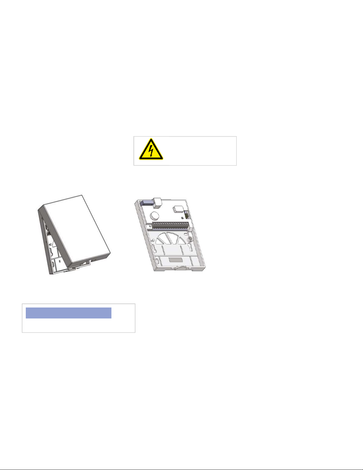
Mounting
• This device is suitable for wall
mounting.
• The device should not be mounted
in dusty environment.
• Ensure that no dust get inside of
this device.
Open the box at the bottom and remove
the front cover! Unplug the ribbon cable
Mount the rear cover on a wall or on a
flush-mounting box.
NOTICE
Make sure to reattach the ribbon cable.
Disconnect the power
supply before wiring
and installation.
Interference
The measurement results of the device can be influenced by external factors.
Possible sources of interference are:
• Air movement, e.g. through windows, doors, by convection, heating.
• Direct sunlight and other heat sources.
• If the device is installed close to electrical consumers e.g. dimmers.
• Vibrations or shocks.
• Pollution due to paint, wallpaper paste and dust from renovation/construction
work
• Organic solvents and their vapours.
• Plasticizers from stickers and packaging: e.g. bubble wrap or polystyrene

5
Wiring diagram
Recommended cable types
A 2 x 2 x 0.8
B 2 x 2 x 0.8
C 2 x 0.8
D 2 x 0.75 (max. 100m)
A
A
A
B
B D
BCC
6
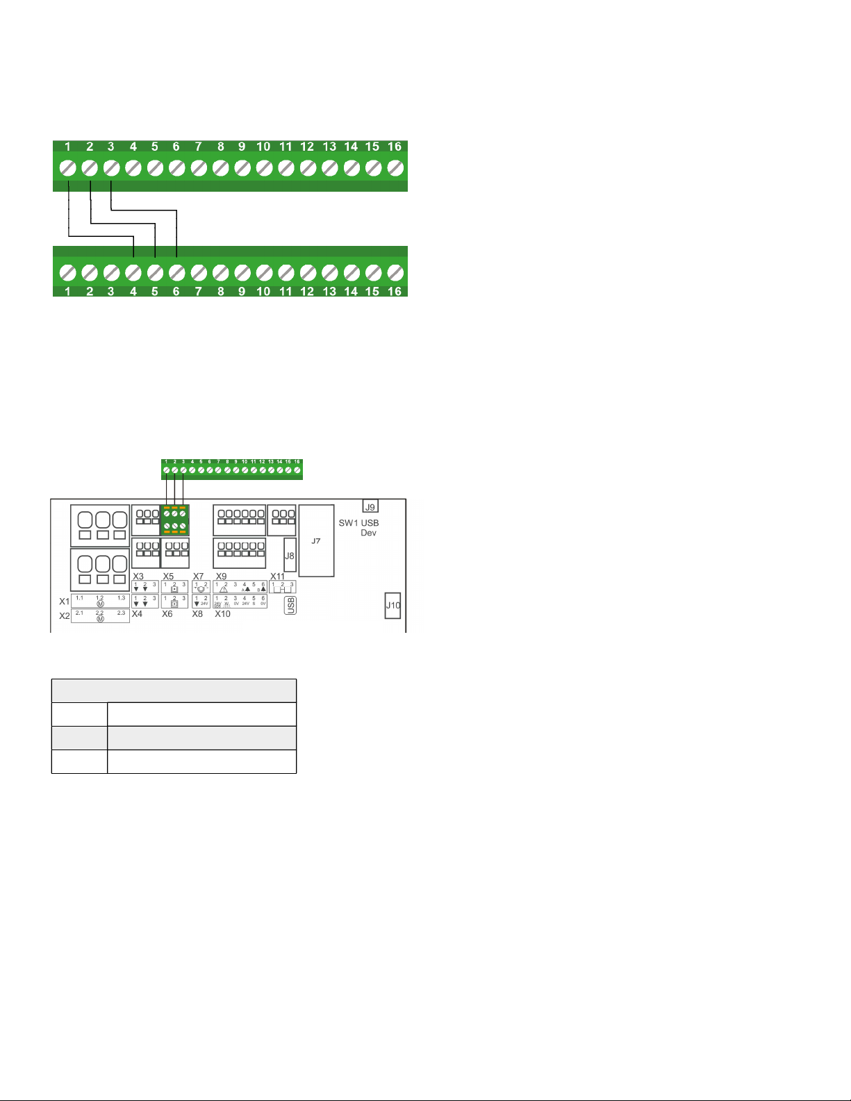
Connections
Connection between two WWS 100
WWS 100 #2
WWS 100 #1
The WWS 100 Sensor is connected to the 5X or 6X on
the panel (the input for break glass unit or Master-Slave
connection).
Connection between WWS 100 and WCC 3x0 Plus
X5 or X6 (WSK-Link™ Master/Slave)
1 24V
2 Comm
3 0V
The WWS 100 Sensor is connected to
the 5X or 6X on the MotorController
(the Master-Slave connection).
Up to 15 sensors can be connected per
MotorController (plus version).
WWS 100 #1
WCC 3x0 P
7
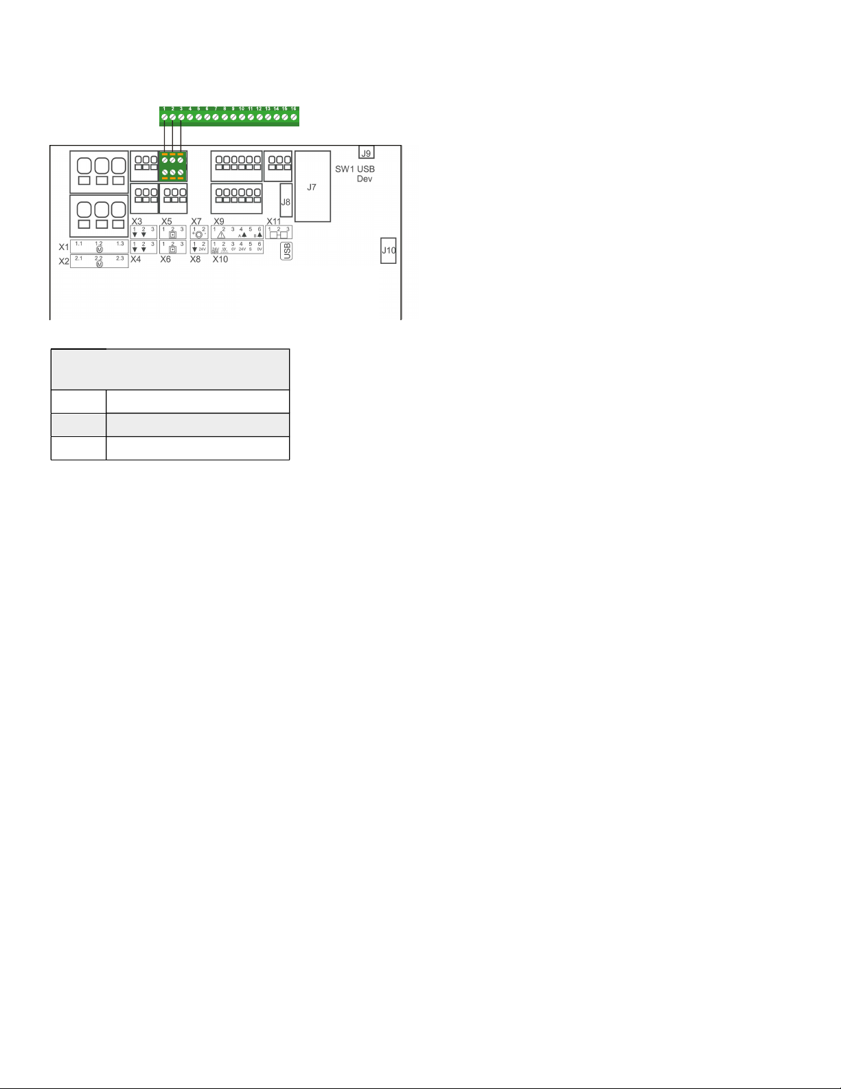
Connection between WWS 100 and WSC 3x0 Plus
X5 or X6
(Break glass unit 1&2)
1 24V
2 Comm
3 0V
The WWS 100 Sensor is connected to
the 5X or 6X on the smoke panel (the
input for break glass unit or Master-Slave
connection).
The max number of sensors, which
can be connected to the smoke panel
depends of type of smoke panel and
number of break glass units (WSK 50x)
also connected to the smoke panel.
Max number of sensor and break glass
units connected to the smoke panel (plus
version):
WSC 310 P:
•
1 x WWS 100 + 5 x WSK 50x
or
•
2 x WWS 100 + 2 x WSK 50x
WSC 320 P:
•
2 x WWS 100 + 10 x WSK 50x
or
•
3 x WWS 100 + 5 x WSK 50x
WWS 100
WSC 3x0 P
8
Technical data
Power supply
Via WSK-Link™
Bus current
< 10 mA
Bus system
WSK-Link™
Sensors
CO
2
, relative humidity, temperature, atmospheric
pressure
CO
2
meassurement
±150 ppm during lifetime at 25°C and 950 - 1050
hPa
Humidity meassurement,
relative
0–100%
Temperature
meassurement
0–50°C, ±0.5°C at 25°and ±1°at 0..50°C
Operating conditions
0–50°C, for indoor wall mounting and must not be
mounted in dusty surroundings or covered
Material
Self-extinguishing thermoplastic
Mounting
Wall
Type of connection
WSK-Link™
IP rating
IP 20 to DIN EN 60529
Class of protection
III when installed according to regulations
Calibration CO
2
Factory calibrated to better than ±50 ppm at 600ppm
and 1000ppm. Auto calibration via ABC-Logic™
Handling
Do not expose to mechanical shock or vibration
Dimensions
83 x 114 x 24mm (WxHxD)
Colour
Studio white (similar to RAL 9016)

9
WWS 100
Raumsensor, Installationshandbuch
Inhalt
Sicherheit 10
Verwendung 11
Betriebsumgebung 11
Betrieb 11
Störungen 12
Montage 12
Schaltplan 13
Verbindungen 14
Verbindung zwischen zwei WWS 100 14
Verbindung zwischen WWS 100 und WCC 3x0 Plus 14
Verbindung zwischen WWS 100 und WSC 3x0 Plus 15
Technische Daten 16
10
Sicherheit
!
WARNUNG
230V AC kann zum Tod und zu schweren Verletzungen führen, oder erheblichen
Schaden an Geräten anrichten. Die Installation und der Anschluss dieses Produkts
darf nur von Fachkräften durchgeführt werden.
!
VORSICHT
• Lesen und verstehen Sie das Handbuch vollständig, bevor Sie das Gerät
verwenden.
• Gestatten Sie nur entsprechend ausgebildeten, qualifi zierten und fähigen
Mitarbeitern, die Installation durchzuführen.
• Verwenden Sie dieses Produkt nur so, wie es in diesem Handbuch angegeben
ist.
• Unsachgemäße Nutzung dieses Produkts kann zu Schäden an Eigentum oder
zu Verletzungen bei Personen führen.
• Führen Sie keine Reparaturen, Demontagen, Montagen, Erweiterungen,
Neueinstellungen oder Modifi kationen an diesem Produkt durch. Diese
müssen von WindowMaster oder von Personen durchgeführt werden, die
ausschließlich von WindowMaster dazu berechtigt wurden.
• Verwenden Sie dieses Produkt nicht, wenn es defekt oder beschädigt ist.
Verwenden Sie ein defektes Produkt erst wieder, nachdem es repariert wurde.
• Der zuverlässige Betrieb ohne Schäden und Gefahren kann nur gewährleistet
werden, wenn die Installation und die Konfi guration sorgfältig anhand dieser
Anweisungen durchgeführt wurde.
• Überprüfen Sie stets, ob Ihr System den gültigen nationalen Bestimmungen
entspricht.
• Nur an eine passende Spannungsquelle anschließen.
• Beachten Sie die Bestimmungen und Anweisungen im ZVEI/ZVEH-Handbuch
(Gebäude-Systemtechnologie).
Table of contents
Languages:
Other WindowMaster Accessories manuals


