INSPECTION
Carefully unpack and inspect your ma
-
chine for shipping damage. Each unit is
operated and thoroughly inspected before
shipment, and any damage Is the re
-
sponsibility of the delivering carrier who
?
should be notified immediately.
ELECTRICAL
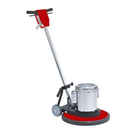
This rotary polisher is designed to oper
-
ate on a standard 15 amp,
115
volt,
60
hz,
AC household current. Check that the
voltage shown on the serial number plate
is suitable for the supply available. Volt
-
ages below 105 volts or above 125 volts
could cause damage to the motor.
NOTE
230 volt 50 hz model is available.
G
RO
U
NDING
I
NSTRUCTIONS
This machine must be grounded. If it
should maifunctionor breakdown,ground
-
ing providesa path of least resistance for
electric current to reduce the risk of
electric shock. This machine is equipped
with a cord having an equipment rounding
conductor and grounding plug.yhe plug
must
be
plugged into an appropriate outlet
that is properly installed and grounded in
accordance wlth all local codes and
ordinances.
WARNING:
improper connection of
the equipment
-
groundingconductor can
result in a risk of electric shock. Check
with a qualified electrician or service
person
if
you are in doubt as to whether
the outlet is properly grounded.
Do
not
modify the plug providedwith the appliance
-
If
It will not fit the outlet, have a proper
outlet installed by a qualified electrician.
This machine is for use on a nominal
120
-
voltcircuit, and has a grounded plug
that looks like the plug illustrated
In
Fig.
A.
A
temporary adapter that looks like the
adapter illustrated in Figs.
B
and C may
be used to connect this plug to a 2-pOle
receptacleas shown inFig.
B
If
a properly
grounded outlet is not available. The
temporary adapter should be used only
until a properly grounded outlet (Fig. A)
can be installedby a qualified electrician.
The green colored rigid ear, lug, or the
like extendlng from the adapter must be
connected to a permanent ground such
as a
properly grounded outlet box cover.
Whenever the adapter is used, it must be
held inplace by a metalscrew.
GROUNDING
PIN
(A)
.
ADAPTER
GROUNDED
OUTLET
BOX
CONTROLS
TOP
OF
SWITCH
HOUSING
Safety Interlock Thumb Levers
and squeeze
Circuit Breaker switch lever
I
I
2
Slide outward
and squeeze
Circuit Breaker switch lever
‘T
Indicator
light
ON
when machine
is
connected
to
electrical
outlet.
To put machlhe in “store” position
. .
.
squeeze handle adjusting lever and fold
main handle forward. Release adjusting
lever to lock handle. Lift up on main
handleto store machine.
MACH
IN
E
PREPARATION
WARNING:
Always remove the power
cord from the electrical outlet before
in
-
stalling or changing the polishing pad.
The drive pad is bolted to the machine.
A
threaded pad holder holds the polishing
padto the driver.
To
install polishingpad
1.
With the handle locked in the upright
position, tilt the machine back until
the handle
is
resting on the
floor
ex
-
posingthe drive pad.
2.
Remove the pad holder by turning
counterclockwise.
3.
Put the polishing pad on the drive pad
makingsure the pad iscentered. Install
the pad holderby turning clockwise.
Pullpolishing pad away from drive pad in
several places to insure pad is centered
on drive pad.
With the pad properly installed return
machineto upright position.
OPERATING THE MACHINE
The L1500-20is a high speed floor polish
-
ing machineand should be operated in a
straight line
-
forward and rearwad
-
not sideto side as you would a low speed
polisher. Use the machine for olishin
DO NOT USE THE MACHINE
fOR
W&
SCRUBBING.
CAUTION:
To prevent possibledamage
to the floor surface, always keep the
machine moving when the ad is in con
-
tact wlth the floor.
DO
NO$
LIFT
UP
ON
THE HANDLETO APPLY PAD PRESSURE.
KEEP THE WHEELS
ON
THE FLOOR AT
ALL TIMES.
TO START THE MACHINE
CAUTION:
Because of the high starting
torque of the machine make sure you
hold the handlewith both hands.
1.
Plug machine into the power su ply
and check that the red indicator {ght
(located on top of switch housing) is
on.
2
Pull up on the adjusting lever and
lower the handle to a comfortable
working height. Release adjusting
lever to lock handle inplace.
3


