Solark L8K-2P User manual

March 22nd , 2022 1
UPON RECEIVING SHIPMENT ................................................................................................................................. 4
SPEC SHEET............................................................................................................................................................ 5
WIRE GAUGE GUIDE (COPPER)............................................................................................................................... 7
WIRING DIAGRAMS ............................................................................................................................................... 8
GUI SCREENS........................................................................................................................................................ 11
PHYSICAL INSTALLATION ..................................................................................................................................... 13
INVERTER COMPONENTS................................................................................................................................................13
DECIDING BACKUP CIRCUITS...........................................................................................................................................13
MOUNTING THE SOL-ARK..............................................................................................................................................14
INTEGRATING BATTERIES (SOL-ARK POWERED “OFF”).....................................................................................................14
CONNECTING SOLAR PANELS ..........................................................................................................................................15
INTEGRATING A GENERATOR...........................................................................................................................................16
INTEGRATING SENSORS AND ACCESSORY PLACEMENT..........................................................................................................17
WIRING THE GRID AND BACKUP LOADS ............................................................................................................................19
POWERING-UP AND TESTING THE SOL-ARK L8K-2P ...........................................................................................................21
CHECK THE VOLTAGE ON EACH PV INPUT CIRCUIT ...............................................................................................................21
WI-FI / INTERNET CONNECTION........................................................................................................................... 22
REMOTE MONITORING SETUP ........................................................................................................................................22
IP ADDRESS SETUP INSTRUCTIONS (PC OR SMART PHONE) ..................................................................................................25
PROGRAMMING GUIDE ....................................................................................................................................... 27
MAIN SCREENS (TOUCHSCREEN).....................................................................................................................................28
BASIC SETUP ...............................................................................................................................................................29
SYSTEM ALARMS..........................................................................................................................................................29
BATTERY SETUP ...........................................................................................................................................................30
GRID SETUP ................................................................................................................................................................32
LIMITER SENSOR AUTOMATIC SETUP................................................................................................................................35
INSTALL TIPS ........................................................................................................................................................ 36
OFF-GRID INSTALL TIPS.................................................................................................................................................36
GRID-TIE /NO BATTERY INSTALL TIPS ..............................................................................................................................36
BATTERIES…………………………………………………………………………………………………………………………………………………………37
BATTERY CHARGING INFORMATION .................................................................................................................................37
MODBUS/RJ45 APPLICATION NOTE..............................................................................................................................39
TROUBLESHOOTING GUIDE.................................................................................................................................. 40
TROUBLESHOOTING PHASING ISSUES................................................................................................................................41
SOL-ARK L8K-2P ERROR CODES.....................................................................................................................................42
INSTALL VERIFICATION CHECKLIST ....................................................................................................................... 43
SOL-ARK L8K-2P LIMITED WARRANTY.................................................................................................................. 44
SOL-ARK L8K-2P INSTALL GUIDE & OWNER’S MANUAL
L8K-2P

March 22nd , 2022 2
Disclaimer
UNLESS SPECIFICALLY AGREED TO IN WRITING, SOL-ARK:
(a) MAKES NO WARRANTY REGARDING THE ACCURACY, SUFFICIENCY, OR SUITABILITY OF ANY TECHNICAL
OR OTHER INFORMATION PROVIDED IN ITS MANUALS OR OTHER DOCUMENTATION.
(b) ASSUMES NO RESPONSIBILITY OR LIABILITY FOR LOSS OR DAMAGE, WHETHER DIRECT, INDIRECT,
CONSEQUENTIAL, OR INCIDENTAL, WHICH MIGHT ARISE OUT OF THE USE OF SUCH INFORMATION. THE USE
OF ANY SUCH INFORMATION WILL BE ENTIRELY AT THE USER’S RISK.
Sol-Ark cannot be responsible for system failure, damages, or injury resulting from improper installation of
their products.
The information included in this manual is subject to change without notice.
This version is for OUTDOOR MODELS ONLY; previous hardware versions of the Sol-Ark L8K-2P are
not compatible with the wire diagrams and instructions contained herein.
March 22nd , 2022 3
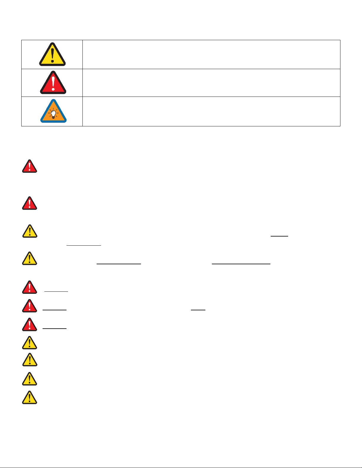
Warning Symbols
This symbol indicates information that, if ignored, could result in minor injury or
damage to the equipment.
This symbol indicates information that, if ignored, could result in serious injury,
damage to the equipment, or death.
This symbol indicates information that is important but not hazard-related.
Warnings
Read this entire document before installing or using the Sol-Ark L8K-2P inverter. Failure to follow any
of the instructions or warnings in this document can result in electrical shock, serious injury, or
death. Damage to the L8K-2P inverter is also possible, potentially rendering it inoperable.
High Life Risk Due to Fire or Electrocution –ONLY qualified persons should install the Sol-Ark L8K-2P
inverter.
The system must have Ground connections and Neutral connections. Ground MUST be bonded to
Neutral ONLY ONCE in the circuit.
Solar PV+/PV- are UNGROUNDED. Note, you may ground PV Racking/Mounts, but doing so directly
to the Sol-Ark will likely result in damage in the case of a direct lightning strike to the PV array.
DO NOT connect the grid to the Load Output Breaker.
DO NOT reverse the polarity of batteries. Damage WILL occur.
DO NOT exceed more than 500Voc on any MPPT on the Sol-Ark.
DO NOT use impact drivers to tighten any fasteners on the Sol-Ark.
MUST use Strain Reliefs ON ALL wires entering/exiting the Sol-Ark L8K-2P user area.
MUST use conduit (or double insulated wire) for AC Wires entering/exiting Sol-Ark L8K-2P user area.
ALL terminals/breakers including battery, MPPT, and AC breaker inputs should only have one
conductor connecting to them.

March 22nd , 2022 4
Inspect Shipment
A. Compare the package condition to the condition of the package in the photo we sent you
before it left our facility.
B. If damaged, contact us immediately at 972-575-8875 Ext. 3
Component Guide
A. Limiter Sensors included: 5/8”CT sensors x2 (Inlcuded)
B. Limiter Sensors if purchased: 15/16”CT sensors x2 (Sold Seperately)
C. Limiter Sensors if purchased: 2”CT sensors x2 (Sold Separately)
D. Battery Temperature Sensor: for voltage adjustment
E. Battery Cable Toroid x2
F. CAT 5 cable for parallel communications
G. WIFI Dongle: For software updates and remote monitoring (use M4x10 screws to hold in)
H. French Cleat: For wall mounting the Sol-Ark L8K-2P
You must note any damage due to shipping with delivery driver before
accepting the package otherwise the shipping company will deny any claim.
Upon Receiving Shipment

March 22nd , 2022 5
Spec Sheet
5
March 22nd , 2022 6
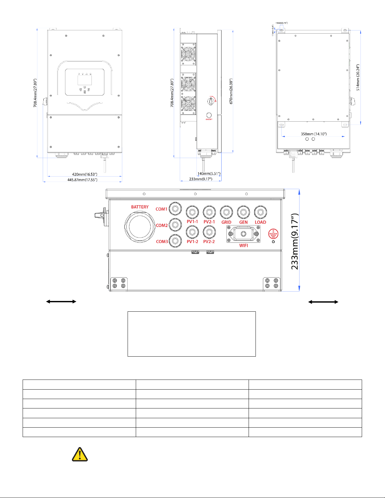
Sol-Ark L8K-2P Torque Values Application Note
Load Breaker
26.5 IN Lbs
3 NM
Grid Breaker
26.5 IN Lbs
3 NM
Gen Breaker
26.5 IN Lbs
3 NM
Neutral / Ground Busbars
26.5 IN Lbs
3 NM
Cover Screws
26.5 IN Lbs
3 NM
Battery Connection
90.0 IN Lbs
10 NM
6”
6” minimum clearance
6”
Temperature Derating
DC: 90C-100C Shutdown @ 100C
AC: 75C-82C Shutdown @ 82C
Do Not Use Impact Drivers to Tighten Any Fasteners on the Sol-Ark.

March 22nd , 2022 7
Wire Gauge Guide (copper)
PV input: 12AWG
All AC Inputs/Outputs: 6-4AWG
All Sensors: 20-24AWG
CT Sensors: 10' Wire Included
Batt Temp Sensor: 6' Wire Included
RJ45 Cable: 7' Included (Extendable up to 20')
Battery input: 2 AWG (M10 Connector)
All Sensor Inputs
0’ –100’: 24 AWG
100’ –400’: 23 AWG CAT 6
Extensions for Limiter Sensors
must be twisted pair
(Shielded CAT6 Recommended)
DC Battery Input
0’ –12’: 2/0 AWG
12’ –20’: 4/0 AWG
All AC Inputs / Outputs /
Neutral Connections
0’ –100’: 6 AWG
100’ –200’: 4 AWG
2/0 AWG Max
4/0 AWG Max
Small
Limiter
Sensor
Inputs
Large
Limiter
Sensor
15.875mm (5/8in)
10 AWG Max
PV Panel Inputs
0’ –100’: 12 AWG
100’ –300’: 10 AWG
25.4mm (1.0in)
Max
10mm
(1/2in)
4/0 AWG Max
15.875mm (5/8in)
4 AWG Max
100A: 50mA
+
-
100A: 50mA
+
-
CAT
6
6.35mm
(1/4in)
20 AWG Max
Max
200A: 0.1A
+
-
23.813mm (15/16in)
100A: 50mA
15.875mm (5/8in)
+
-

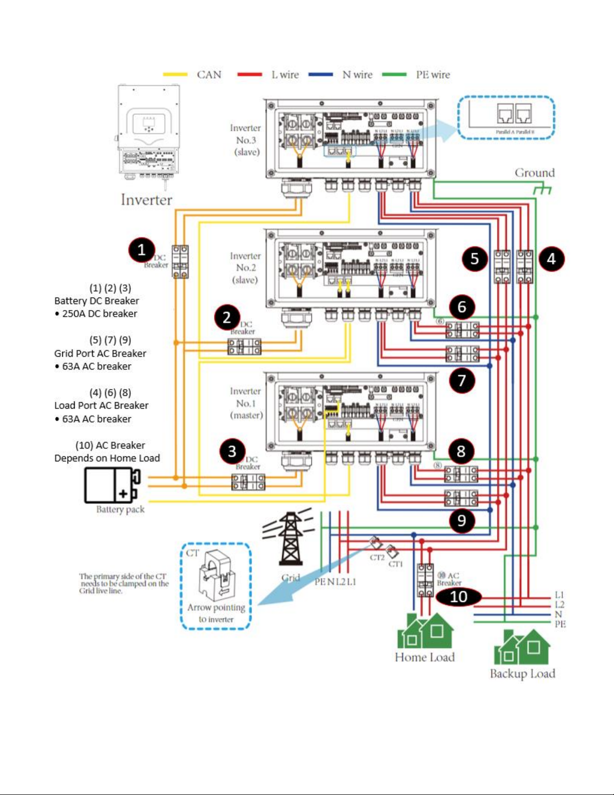
March 22nd , 2022 9
Sol-Ark L8K-2P x3 Standard Wiring Diagram (120/240V)

March 22nd , 2022 10
This page is left blank on purpose

March 22nd , 2022 11
GUI Screens
Main Menus
Basic Setup

March 22nd , 2022 12
c
Battery Setup
Grid Setup
March 22nd , 2022 13
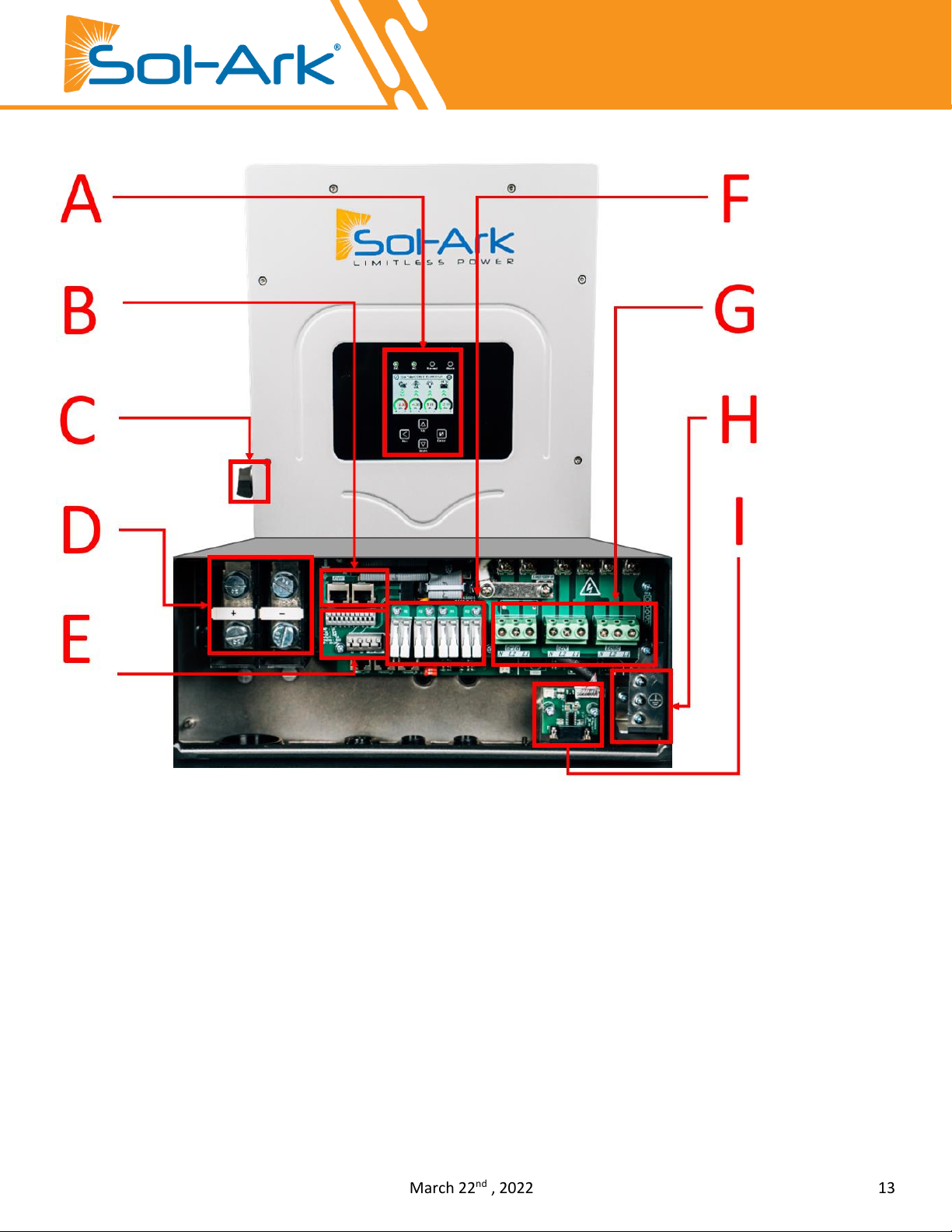
Physical Installation
Inverter Components
A. LCD Touch Screen F. MPPT Charge Controllers
B. Comms/Paralleling Ports G. AC Terminal Blocks
C. PV DC Disconnect Switch H. Neutral/Ground Bus Bar
D. Battery Terminals (+/-) I. Wi-Fi Connection
E. Sensor Pinout J. ON/OFF button
Deciding Backup Circuits
A. We recommend subpanels and require them if you have Arc-Fault / GFI breakers
B. Ensure you keep the inverter within its amperage limits
•ON-Grid = 50A Continuous (pass-through)
•OFF-Grid = 37.5A Continuous | 67A Peak (10s) | 104A Peak (100ms)
C. Verify each load circuit by measuring typical and max Amps with a clip-on Amp meter. Amps x 120V = Watts
D. Install a subpanel for backup loads if you have Arc-Fault / GFI breakers, NOT a multi-circuit transfer switch

March 22nd , 2022 14
Mounting the Sol-Ark
A. Keeping in mind Sol-Ark’s dimensions, find a suitable location for the system(s)
B. NEMA 3R rating for Outdoor installations
C. PROTECT the LCD screen from excessive UV exposure
D. System weight = 70.5 lbs (32 kg). Securely attach to the wall. Affix a mounting board to studs using 6-8 screws
E. Use 2-3 screws + washers (choose screw length and surface type) to mount the Sol-Ark to the board/wall
F. Mount Sol-Ark on the board/wall and ensure Sol-Ark is level
G. Add two screws for the bottom mount
Integrating Batteries (Sol-Ark POWERED “OFF”)
Install a separate DC over-current protector or disconnect device between the battery and the inverter for safe
operation and compliance. Switching devices may not be necessary for some applications, but over-current protectors
are still needed.
A. Please choose a suitable battery cable with the correct connector that fits well into the battery terminals
B. Use a suitable screwdriver to unscrew the bolts and fit the battery connectors in, then fasten the bolt by the
screwdriver, make sure the bolts are tightened with a clockwise torque of 24.5 N.M
C. Connect batteries to Sol-Ark as shown in Fig. B below
D. Install included toroids (Part e. on pg. 4) on battery input cables as shown in Fig. A
to the right
Do NOT reverse
polarity of
batteries! Damage
will occur!
Fig. A

March 22nd , 2022 15
Connecting Solar Panels
Before conneng to PV modules, please install a separately DC circuit breaker between inverter and PV modules.
A. Sol-Ark has DUAL MPPTs for two separate PV input pairs
B. MAX PV input = 10.4kW (± 5%) / system | 5.2kW / MPPT | MAX 500VOC PV | MAX ISC /MPPT 28A
Damage will occur if PV VOC > 500V
C. Parallel strings per MPPT must be the same Voltage
i. PV1 A/B must be the same voltage if using both strings
ii. Panels on the same MPPT CAN face different directions
D. Ground the panel MOUNTS/FRAMES to any ground in the Home via 12AWG wire
E. IF using Y-Connectors: Running two strings in parallel, totaling 28A (self-limiting)
F. Connect the solar panel strings as indicated by the following diagram (12AWG):
Positive to
Sol-Ark
Negative
to Sol-Ark
Sol-Ark 8K is a 48V system. Do NOT wire the
battery bank to any other nominal voltage.
When using 12V batteries do not exceed
FOUR (4) batteries in series.
When using other battery chemistries, stay
within the voltage range: MIN 43V-MAX 63V
Do NOT stack more than 2
banks high
PCC batts are
stackable
Each string can use separate
wires
String minimum is usually 5
panels or 150V
Fig. B

March 22nd , 2022 16
Integrating a Generator
Generators < 10kW (GEN Breaker)—See Diagram 1-2
A. ONLY supports 240V generators | 50A breaker
B. Connect the generator output to the “GEN”input breaker in the Sol-
Ark L8K-2P user area
C. THD of less than 15% preferred but not required
Standby Generators > 10kW (GRID Breaker)—See
Diagram 1 (OFF-GRID)
A. Supports 240V generators
B. Off-Grid / Whole-home Generator on ATS installations require selecting
“GEN Connected to Grid Input”
Home Screen → Gear Icon → Grid Setup → Sell Control →GEN
Connected to Grid Input
C. Off-Grid = turn “Grid Sell”off
Gen Start V or %
Value batts need to reach BEFORE automatically starting a generator connected
to the GEN breaker to charge the battery bank.
Sol-Ark will NOT charge batteries from a generator until the batteries
reach this value.
Gen Start A
This is how many amps (DC) you can pull specifically from the Generator (GEN
breaker only) to charge the batts. To ensure you do not overload a small
Generator, you will want to adjust the GEN charge value. Multiply value by # of
Sol-Arks for actual current value into batteries.
Increase Gen/Sol-Ark efficiency
1. Select “Limited to Load” 2. Select “General Standard”
3. Increase Grid frequency range: 55-65H
Suppose PV production = 0W | Disabled TOU | Enabled Grid/Gen Charge: the batteries will be
charged to "full" using the Grid or a Generator (if available) until the battery bank accepts only
5% of its rated capacity in Amperes. This value correlates to roughly 90-93% full for most
batteries and is the generator's default "OFF" signal. If producing PV, the system will use PV to
charge the batteries to 100% full instead.
Weekly Gen Exercise
If the Sol-Ark is up to date with MCU
version xx73 or newer, and your
generator has two-wire start
compatibility, you will experience
weekly generator tests.
These tests occur at 8AM (local time)
every Monday by default.
The test takes approximately 20
minutes to complete. During that
time, the generator will auto-start
and auto-stop.
The generator will not provide
power during this test. The
generator may charge the batteries
if the batteries reach designated
generator start point, however.
March 22nd , 2022 17
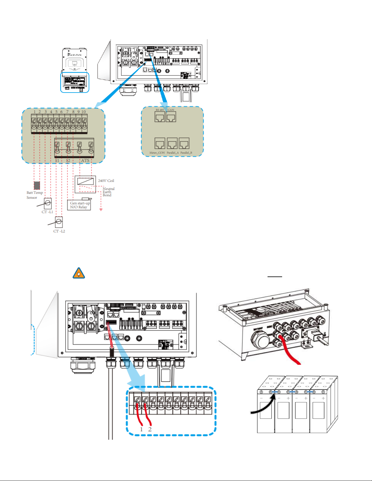
Integrating Sensors and Accessory Placement
Battery Temperature Sensor
•Place between batteries with tape (See Fig. C) and connect to pins 1 and 2
•This sensor has no polarity and helps perform voltage charging adjustments and capacity calculations.
Note: Lithium Batteries do NOT require a Temperature sensor.
Fig. C
(1,2) Batt Temp: Battery Temperature
Sensor has no polarity and is needed for
voltage correction when using lead acid
batteries.
(+3, -4) CT1 & (+5, -6) CT2: Current
transformers used for limited to home
mode and peak shaving
(7,8) Gen Start Relay: Two wire start for
generators, simple open or closed relay
(+11, -12) RSD: 12V power supply for RSD
transmitters
ATS: 240V output port when the inverter is
active
RS 485: RS 485 port for battery comms
CAN: CAN port for battery comms
Parallel A: Parallel comms port 1 (CAN)
Parallel B: Parallel comms port 2 (CAN)
Meter_CON: for energy meter comms
March 22nd , 2022 18
GEN Start Signal (Two-Wire)
•The signal comes from a normally open relay that closes when the Gen
Start state is active
CANbus & RS485
•To connect batteries to the Sol-Ark L8K-2P via RJ45, you need to splice
the end connecting to the Sol-Ark L8K-2P
•Use the middle two conductors
•RS485 is SunSpec draft 4 (will not work with draft 3)
Wi-Fi Antenna (Dongle)
Remote monitoring and software updates require an internet connection through the Wi-Fi dongle
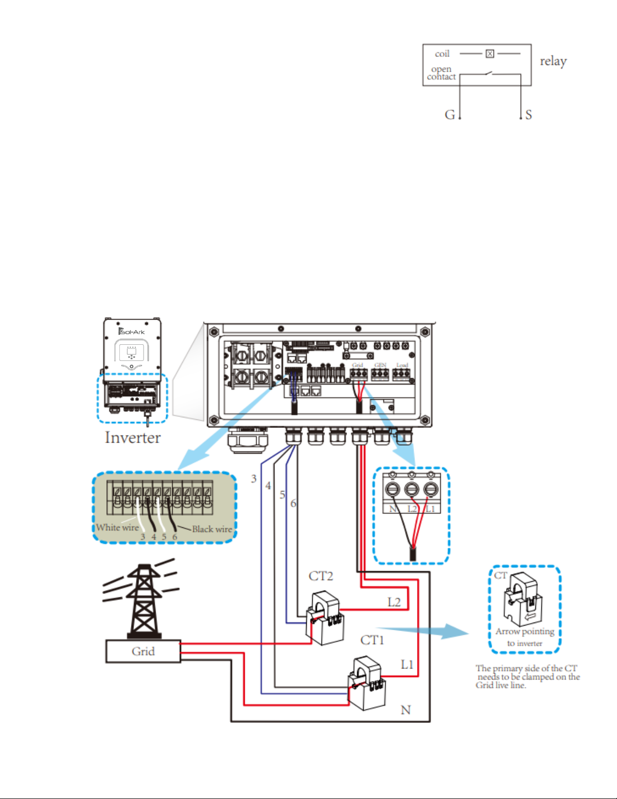
Limiter Sensors (CT Sensors) Diagram Below
•Install sensors on incoming electrical service wires on L1 and L2 Limited to Home Mode (meter zero) and Peak
Shaving Modes require CT sensors
•CT winding default ratio is 2000:1; however, this ratio is programmable
•To ensure the sensors will fit, please check the wire size before ordering
Limiter Sensor Diagram
If CT data is wrong, reverse
CT direction and point the
arrow towards the grid
March 22nd , 2022 19
Misc. Hardware Recommendations
Disconnect / Transfer Switches: 200A Non-Fused Transfer Switch Model #TC10324R (GE) | 200A Fused
Transfer Switch Model #DG224NRK (Eaton)
PV Fuses: 15A PV MC4 in-line fuse holder (ZOOKOTO or DPJ)
Electrical Panel: Any appropriately rated panel for your loads (Check local hardware stores for recommendations)
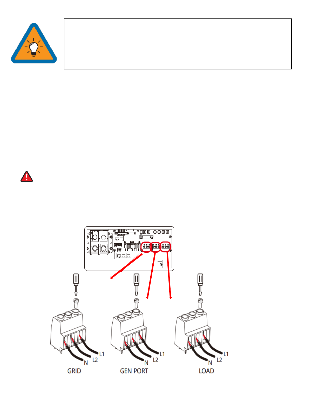
Wiring the Grid and Backup Loads
Before connecting to the grid, please install a separate AC breaker between the inverter and grid. Also, we recommend
installing an AC breaker between the backup load and inverter to ensure the inverter can be securely disconnected
during maintenance and fully protected from overcurrent. We recommend a 63A breaker and 10AWG AC wire size.
There are three terminal blocks with “Grid," “Load,” and “GEN” markings. Please do not misconnect input and
output connectors.
A. Turn OFF the AC breaker or disconnector BEFORE making a grid, load, or gen connection
B. Remove insulation sleeve 10mm length, unscrew the bolts, insert the wires according to polarities indicated on
the terminal block and tighten the terminal screws. Make sure the connection is complete
C. Insert AC output wires according to the polarities indicated on the terminal block and tighten the terminal.
D. Be sure to connect corresponding Neutral and Ground wires to their respective terminals
E. Make sure the wires are securely connected
•The Built-in 12V power supply in the user area of the Sol-Ark (Pins 11 and 12) is rated for
100mA (1.2W)
•Transmitter fits inside the user area of the Sol-Ark 8K but can cause interference
(sometimes requires placing it outside of the user area)
•TIGO Optimizers are compatible with the Sol-Ark 8K (Do not use the built in 12V Power
supply in the Sol-Ark user area to Power the Tigo Optimizer TX transmitter)
GRID
GEN
LOAD
March 22nd , 2022 20
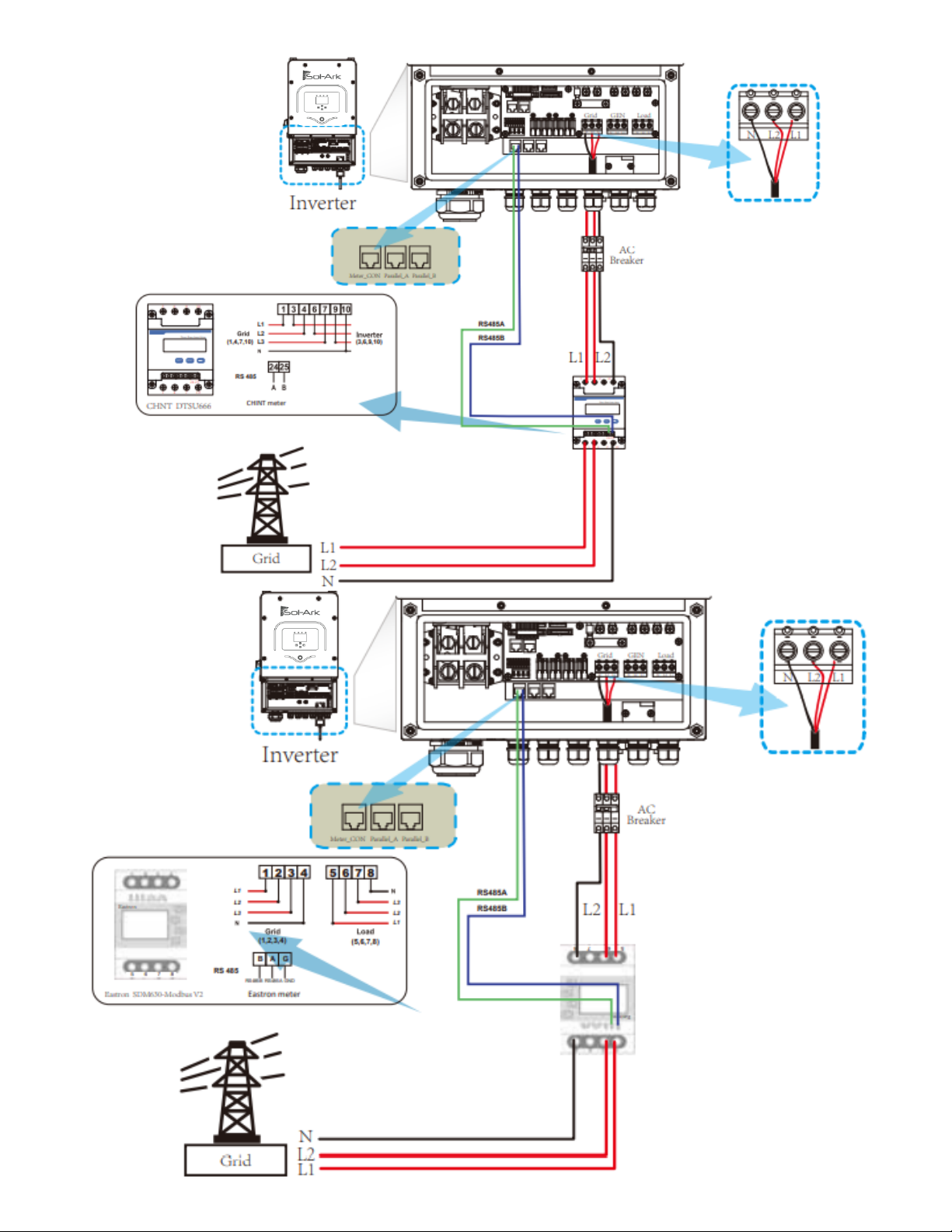
Meter Connection
Table of contents
Other Solark Inverter manuals

Solark
Solark 5K-P User manual

Solark
Solark 5K-2P-N Assembly instructions

Solark
Solark 8K-2P-N User manual

Solark
Solark 12K User manual

Solark
Solark SA-5K-1P Assembly instructions

Solark
Solark 8K-P User manual

Solark
Solark 12K User manual

Solark
Solark 8K User manual

Solark
Solark 8K-1P-N Assembly instructions

Solark
Solark 8K User manual

Solark
Solark 5K-2P-N User manual

Solark
Solark 5K-IP-N Assembly instructions

Solark
Solark 8K User manual

Solark
Solark 5K User manual

Solark
Solark LATAM 12K-3P-L Troubleshooting guide

Solark
Solark 60K-3P-N User manual

Solark
Solark 5K-1P-N User manual

Solark
Solark 5K User manual

Solark
Solark 8K-2P-L User manual

Solark
Solark 5K User manual


