LTE-A
LTE-V
CELLULAR
PCS
AWS
POWER
LTE-A
LTE-V
CELLULAR
PCS
AWS
POWER
LTE-A
LTE-V
CELLULAR
PCS
AWS
POWER
LTE-A
LTE-V
CELLULAR
PCS
AWS
POWER
To Outside
Antenna
Inside Whip
Antenna
Power
Jack
AC power
or
DC power
LTE-A
LTE-V
CELLULAR
PCS
AWS
POWER
LTE-A
LTE-V
CELLULAR
PCS
AWS
POWER
antenna
washer
mount
lock washer
bolt
LTE-A
LTE-V
CELLULAR
PCS
AWS
POWER
LTE-A
LTE-V
CELLULAR
PCS
AWS
POWER
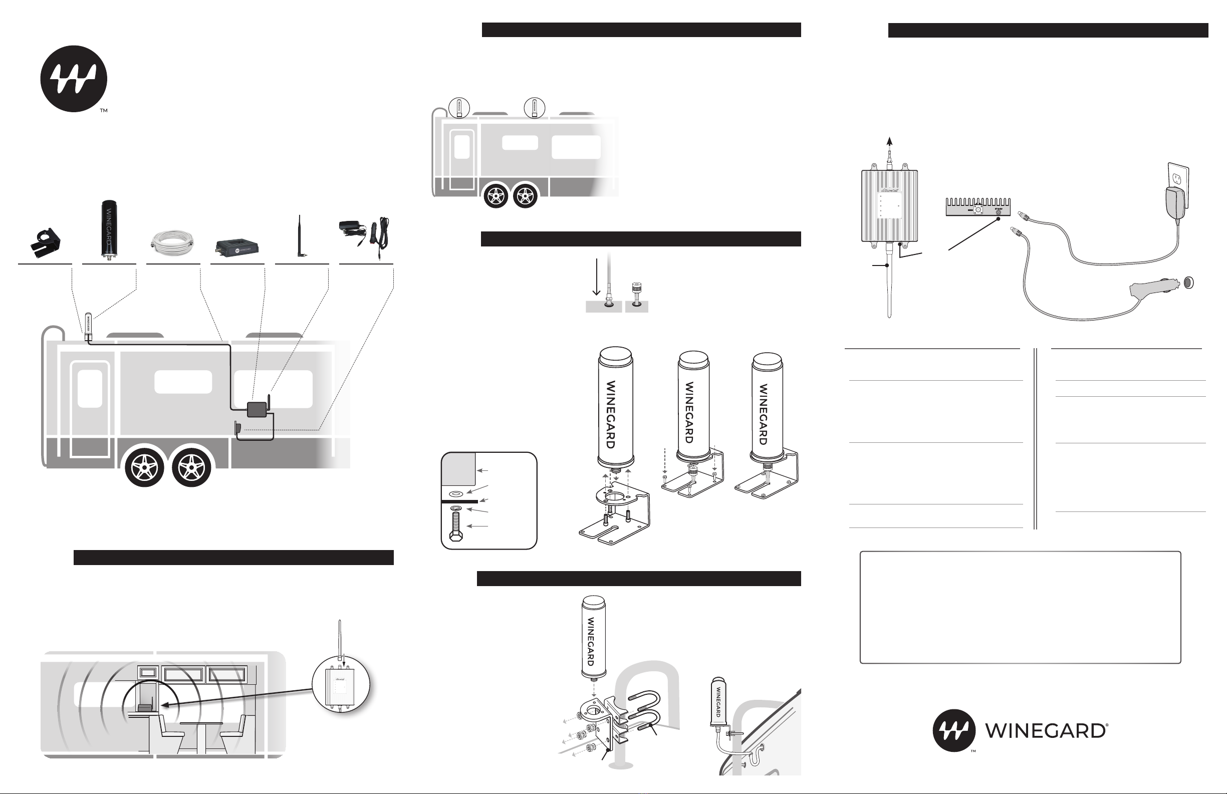
RV Roof
Mount
Coax Cable
(40 ft)
RangePro
Signal Booster
AC or DC
Power
Adapter
Outside Omni-
directional
Antenna
Inside
Whip Antenna
Note: To avoid possible interference, mount the
antenna at least 15' away from the indoor booster
and allow at least 3' from other RF products (such
as satellites and over-the-air antennas).
The outside antenna must not be collocated or
operating with any other antenna or booster.
Maximum height restriction is 31' 9" (10 meters)
above ground.
We advise you first perform a “soft” installation
by routing the outside antenna cable through an
open window (step 4). After completing the “soft”
installation and verifying successful operation,
proceed with installing the external antenna.
Select a location for the outside antenna that
is above the roofline. The outside antenna is
omni-directional, which receives and sends signals
in a 360-degree radius. For maximum performance,
mount the antenna at the highest possible location
outside the vehicle and in an upright position, but
also ensure this is a spot where you can drill a hole
for cable entry.
1. Inside the vehicle, connect the cable leading to the
outside antenna to the port on the booster labeled
“OUTSIDE.” Make sure that all connections are
secure before powering on.
2. Finish permanent cable installation by securing
any loose cables inside the vehicle.
3. Connect the AC power adapter (or 12V adapter) to
the signal booster and plug it into power.
The Power LED will light, indicating that the signal
booster is ready for use. Place a call in a location you
have previously experienced poor signal and confirm
that your phone is receiving a boosted signal. Normal
operation is indicated by green LEDs (both flashing
and solid). In the event red LEDs appear, antenna
adjustments may be needed.
WARNING: The booster is rated for 6-15V input
voltage. DO NOT use the booster with a higher
voltage power supply. This can damage the
booster and/or cause personal injury.
WINEGARD COMPANY 2736 MT. PLE ASA NT ST. |BURLINGTON, IA 52601 2452456 Rev2-22
Have questions?
We have answers! Reach out to our US-based support team:
Call: 855-433-2291
Visit: www.winegard.com/support
To register your product please visit winegard.com/login and create an
account. You can then register your product(s) by clicking the Manage My
Accounts button.
Manuel disponible en français au www.winegard/support
WB-1035 QUICK SETUP GUIDE
Identify a location for the booster that is near the
center of where signal is needed. The location
should be free from excessive heat, direct sunlight,
or moisture—and provide proper ventilation. (We
suggest you mount the booster within a cabinet or on
a side panel close to a power source.)
Connect the inside whip antenna to the port on
the side of the booster labeled “INSIDE”.
Note: The inside antenna sends signals in a
360-degree radius and should be positioned
vertically.
STEP
STEP
INSTALL THE SIGNAL BOOSTER AND CONNECT INSIDE ANTENNA
SELECT A SITE FOR THE OUTSIDE MOUNT
STEP
CONNECT POWER AND VERIFY SUCCESSFUL OPERATION
LED INDICATORS
Color Condition Indication
Green Solid Indicates normal operation.
Green Flashing Normal operation. Indicates
that Automatic Gain Control
(AGC) is self-adjusting due
to over-signal or antenna
proximity.
Red Flashing Indicates issues caused by
overpowering or oscillation.
Adjust your outside and
inside antenna locations
to maximize separation
between them by increasing
distance as well as adding
obstructions.
TROUBLESHOOTING
Problem Resolution
Signal booster
has no power
Verify that the Power LED is ON.
Connect the power supply to an
alternate power source.
Verify that the power source is
operational and the fuse is intact.
If it remains OFF, contact tech support
at: 1-855-433-2291
After completing
installation, signal
coverage has not
improved
Verify that cable connections are
tightly fitted to the booster.
Try further separating the antennas.
NOTE:Bars are not always a reliable
measure of signal. The best way to
confirm signal coverage is the ability to
place and hold a call.
The booster case
is warm
The booster case may become warm
during operation. This is normal.
6. Position the roof mount over the
cable, threading the cable through
the mount’s channel.
7. Secure the mount on the roof by
inserting and tightening the provided
screws into the four mounting
holes. Verify the provided screws
are approved with the vehicle
manufacturer before installing.
8. Connect the cable to the outside
antenna. Create a moisture barrier
by using manufacturer-approved
permanent sealant around all
screws and holes in the RV roof.
STEP
OR
MOUNT OUTSIDE ANTENNA ON ROOF
MOUNT OUTSIDE ANTENNA USING OPTIONAL LADDER MOUNT
Before you begin, please note that
this installation requires the use
of a ladder, mast or RV mounting
system on which to mount the
outside antenna.
1. Remove the three screws and
washers that are attached to the
outside antenna.
2. Place the antenna through the
hole on the top of the roof mount
and reattach 3 screws and
washers.
3. Assemble the L-bracket with
U-bolts, brackets, nuts and
washers and secure to mast as
shown in the illustration.
4. Secure antenna to the horizontal
plate of L-bracket using screws.
1. After selecting the outside antenna
position, drill the cable hole through the roof
in an area free from other cables or pipes.
2. Feed the small end of the cable through
the hole until only the connector and 1"
of coax remain outside the coach.
3. Remove the three screws and washers that
are attached to the outside antenna.
4. Place the antenna through the
hole on the top of the roof mount.
5. Align the two small holes located on the
bottom side of the antenna with the two
small holes on top of the roof mount. Next,
reattach the three screws and washers
through the roof mount and into the holes
on the base of the antenna.
5. Drill a hole for cable entry on the side
of the vehicle, away from other cables
or pipes. Use a rubber gasket (sold
separately) to protect the cable and
your vehicle surface. Form a drip loop
before entry and create a moisture
barrier using a manufacturer-
approved permanent sealant.
L-bracket
U-bolt
The Winegard RangePro is designed to work with existing cellular signals, and cannot be
used as a standalone cellular hotspot. A cellular plan and device are required for operation.
WINEGARD®
RangePro™
Cell Booster for RVs


