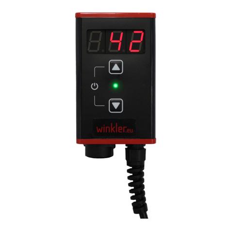
winkler W-700 Series User manual

Operation Manual
Temperature Controller Series W-700
Winkler AG Englerstrasse 24 D-69126 Heidelberg Tel. +49-6221-3646-0 Fax: +49-6221-3646-40 sales@winkler.org www.winkler.org
2 of 25
Rev.0.4 06/02/23
Table of contents
1 Safety information....................................................................................................................... 4
1.1 Place of installation of the unit ................................................................................................... 4
1.2 Instructions for installation ......................................................................................................... 5
2 General information.................................................................................................................... 6
3 Putting into operation................................................................................................................. 6
3.1 Wiring .......................................................................................................................................... 6
3.2 Switching on ................................................................................................................................ 6
3.3 Setup............................................................................................................................................ 7
4 Control elements......................................................................................................................... 8
4.1 Overview of functions ................................................................................................................. 8
4.2 Standard display information...................................................................................................... 8
4.3 Status LED.................................................................................................................................... 9
4.4 Error detection and display......................................................................................................... 9
5 Schematic and mode of operation............................................................................................ 10
6 Operation and settings.............................................................................................................. 11
6.1 Specifying the setpoint.............................................................................................................. 11
7 Settings via the menu................................................................................................................ 11
7.1 Menu structure.......................................................................................................................... 12
8 Menu items ............................................................................................................................... 12
8.1 Controller type .......................................................................................................................... 12
8.2 Controller setup......................................................................................................................... 13
8.3 Limiter type ............................................................................................................................... 14
8.4 Limiter setup.............................................................................................................................. 14
8.5 Sensor A / sensor B.................................................................................................................... 14
8.6 Output ....................................................................................................................................... 15
8.7 Timer ......................................................................................................................................... 15
8.8 Unit............................................................................................................................................ 15
8.9 Language ................................................................................................................................... 15
8.10 Advanced................................................................................................................................... 15
8.11 Power-on option........................................................................................................................ 15
8.12 Stop after error.......................................................................................................................... 15
8.13 Heater check.............................................................................................................................. 16
8.14 Signal output ............................................................................................................................. 16

Operation Manual
Temperature Controller Series W-700
Winkler AG Englerstrasse 24 D-69126 Heidelberg Tel. +49-6221-3646-0 Fax: +49-6221-3646-40 sales@winkler.org www.winkler.org
3 of 25
Rev.0.4 06/02/23
8.15 Password protection ................................................................................................................. 16
8.16 Factory defaults......................................................................................................................... 16
8.17 System info................................................................................................................................ 17
9 Optional communication module ............................................................................................. 17
9.1 Communication module additional menu (optional)................................................................ 17
9.2 Communication module settings (optional).............................................................................. 17
10 Controller on / off...................................................................................................................... 18
11 Application examples ................................................................................................................ 19
11.1 Simple controller operation with one sensor............................................................................ 19
12 Troubleshooting ........................................................................................................................ 20
13 Terminal assignment ................................................................................................................. 21
14 Standard pin assignments ......................................................................................................... 22
15 Repair and maintenance ........................................................................................................... 23
16 Disassembly and disposal.......................................................................................................... 23
17 Drilling template........................................................................................................................ 24
18 EU Declaration of Conformity ................................................................................................... 25

Operation Manual
Temperature Controller Series W-700
Winkler AG Englerstrasse 24 D-69126 Heidelberg Tel. +49-6221-3646-0 Fax: +49-6221-3646-40 sales@winkler.org www.winkler.org
4 of 25
Rev.0.4 06/02/23
1Safety information
Before putting the unit into operation, you must read and ensure compliance with the
safety information, installation instructions and operating manual supplied with the unit.
Please read the safety information carefully and ensure compliance with the instructions, otherwise
the safety of personnel and equipment may be impaired. The unit is predominantly designed as a
temperature controller for electrical heating systems. Improper use, installation, configuration or
operation may cause severe personal injury and extensive damage to property!
Important: This unit is not a safety temperature limiter to DIN EN 60730-1!
The unit must not be installed in potentially explosive atmospheres. If a process function originating
from an explosion-risk area is to be processed by the unit, which is installed outside the explosion-
risk area, all supply lines of the unit leading into the explosion-risk area must be installed using
approved safety barriers!
Error-free and safe operation of the unit requires its careful transportation and storage, as well as
correct assembly and installation. This unit may only be installed, configured, parameterised and
commissioned by qualified persons who are familiar with the installation, commissioning and
maintenance of comparable devices and with the system in which the unit will be used and who have
appropriate knowledge in the field of instrumentation and control. Operating staff of the system in
which the unit is to be used must be instructed by suitably qualified persons on operation and
control of the unit.
Please observe and comply with:
•The contents of the present manual regarding installation and operation of the unit, in
particular the information on installation and putting into operation and any notes in
bold print.
•Any safety information attached to the unit.
•Any relevant safety regulations for installation and operation of electrical systems.
•Safe storage of this manual for future use.
The regulations stated in the present manual are applicable in all EU countries. If the unit is to be
used in a country outside the EU, ensure compliance with the relevant national rules and regulations.
This unit has been manufactured and tested in accordance with DIN EN 61010 Part 1 “Safety
requirements for electrical equipment for measurement, control and laboratory use” and has left our
company in an error-free condition in terms of its safety and functionality.
1.1 Place of installation of the unit
The unit is designed as a temperature controller for flexible application in electrical heating systems.
The place of operation or installation of the temperature controller must not be close to motors,
transformers, circuit breakers or other inductive loads; it must be installed in a vibration-free
location. The ambient temperature at the place of installation must be between −20 °C and 50 °C.
Aggressive gases and vapours may damage the unit.

Operation Manual
Temperature Controller Series W-700
Winkler AG Englerstrasse 24 D-69126 Heidelberg Tel. +49-6221-3646-0 Fax: +49-6221-3646-40 sales@winkler.org www.winkler.org
5 of 25
Rev.0.4 06/02/23
1.2 Instructions for installation
Please read the installation instructions carefully and comply with all points mentioned in them when
installing the unit. Non-compliance with these instructions for installation may result in faults or
malfunctions or the unit may fail to comply with the required EMC guidelines and thus the conditions
for CE-conformity will not be fulfilled.
Before connecting the unit and putting it into operation, please ensure that the operating voltage
and the conditions for the operating voltage required by the unit correspond to the conditions on
site (see name plate and technical data). If required, take any appropriate measures.
Please ensure that the control and load voltage on site are switched off and secured against
accidental reactivation during installation of the unit. The electrical connections must be in
accordance with relevant national rules and regulations. The supply lines for the device must be
installed such that they are free from any tensile loads and are not exposed to risks of shearing or
crushing under any circumstances.
The mains connection and the connections for consumers must each be provided by suitable cables
with a cross-section of at least 1.5 mm².
For sensor lines and signal lines, the use of shielded cables is strongly recommended (especially if
lines are long and/or running along potential sources of interference); for thermocouples, shielded
compensation lines should also be used. Sensor lines and signal lines should be installed such that
they are spatially separated from the load and control lines (high-voltage lines). If signs of incorrect
switching behaviour are detected, the system must be put out of operation until the cause is
eliminated.
Normal terminals may not be used for intermediate clamping of compensation lines for
thermocouples since this would result in the creation of additional thermocouples that could falsify
the measurements.
The controller is designed for the switching of ohmic heating units. Any inductive loads activated by
the unit, such as contactors, valves, motors, transformers, etc. must be wired separately and
provided with unit-specific suppression devices.
When connected to the "Line 10A Fuse int." terminal or type W-720 / W-730, the load circuit is
protected against overcurrent with an internal 5x20mm 10AT fine-wire fuse. When connected to the
"Line unfused" terminal, the load circuit must be protected against overcurrent with a suitable fuse
by the customer.
The present manual does not contain an exhaustive list of all regulations, standards, etc. that must
be observed and complied with when using the unit in combination with other systems and plant.
Any such regulations, standards, etc. shall be complied with and observed by the operator of the unit
with regard to the specific application.

Operation Manual
Temperature Controller Series W-700
Winkler AG Englerstrasse 24 D-69126 Heidelberg Tel. +49-6221-3646-0 Fax: +49-6221-3646-40 sales@winkler.org www.winkler.org
6 of 25
Rev.0.4 06/02/23
2General information
The W-700 temperature controller series offers a wide range of features, intuitive functions and an
extremely long service life. The FAT (fast adaptive tuning) algorithm continually adjusts to the control
loop thus ensuring precise control. The setting of PID parameters and the execution of an autotuning
procedure are not required. All functions can be quickly accessed and changed in the plain-text
menu. The integrated hybrid relay system ensures a long service life with low losses in the controller.
The additionally installed cut-off relay minimises the risk of damage should the hybrid relay fail. The
self-optimising FAT control algorithm makes sure that the target temperature is reached quickly
while avoiding overshoots. The two independent universal sensor inputs allow easy connection of a
variety of common resistance temperature sensors as well as thermocouples. The limiter module
provides additional protection and flexibility in the control strategy. The electronics are protected
against overcurrent and overheating.
The multi-colour LED provides highly visible, simple signalling of the various operating modes.
3Putting into operation
The unit comes supplied with standard parameters. This configuration matches the specific
requirements in very few cases. This means that the unit must be adjusted to the desired
temperature limits of the application and the type of sensor used.
3.1 Wiring
If the unit is supplied ready for connection with plug-in connectors, please ensure the correct pin
assignment of the connectors. All cables used must comply with the relevant current and voltage
requirements.
In the case of units for connection by the user, the front panel must be removed in order to access
the internal terminals. To do this, open the cover and remove the 4 Phillips screws (PH1). If
necessary, remove the front panel from the housing by gently shaking it or pushing the mains cable.
To begin wiring, place the front module next to the enclosure on a non-slip surface. Or if the
enclosure is already wall-mounted, the front module can be clamped under the spacer bolts.
All spring-loaded terminals can be easily activated using a flat-blade screwdriver. For a description of
the terminals, see section 13 Terminal assignment on page 21.
3.2 Switching on
Check the wiring again carefully!
Incorrect wiring of the unit can cause serious damage to the unit and the system! Make sure that the
load voltage of the system is switched off when you switch on the unit for the first time as the unit
has not yet been adjusted to the system and may under certain circumstances trigger malfunctions.
Now switch on the operating voltage of the unit.

Operation Manual
Temperature Controller Series W-700
Winkler AG Englerstrasse 24 D-69126 Heidelberg Tel. +49-6221-3646-0 Fax: +49-6221-3646-40 sales@winkler.org www.winkler.org
7 of 25
Rev.0.4 06/02/23
3.3 Setup
Go to the settings menu and select the desired values for controller type, limiter type, setpoint,
upper limit and lower limit and good range (value corridor) as well as the limit temperature for
monitor or limiter. Configure the temperature sensor used. See section 7 Settings on page 11

Operation Manual
Temperature Controller Series W-700
Winkler AG Englerstrasse 24 D-69126 Heidelberg Tel. +49-6221-3646-0 Fax: +49-6221-3646-40 sales@winkler.org www.winkler.org
8 of 25
Rev.0.4 06/02/23
4Control elements
4.1 Overview of functions
•Open menu: Press and back simultaneously
•Change setpoint: Press and hold up or down
•Acknowledge error: Pressing deletes the error if it has been rectified.
•Controller on / off: Press and hold up and down buttons at the same time
4.2 Standard display information
•Type of controller: Displays the currently selected type of control
•Setpoint: Temperature setting to be maintained by the controller
•Controller actual value: Current temperature measured by the controller sensor
•Switch icon: Displays whether the output is currently switched on
•Type of limiter: Displays the currently selected type of limiter
•Limiter actual value: Current temperature measured by the limiter sensor
•Limit temperature: Temperature setting that should not be exceeded by the limiter
Status LED
OK button
Back button
Up / down buttons
Display
Type of limiter
Limiter actual
value
Limit temperature
Type of controller
Controller actual
value
Setpoint
Switch icon

Operation Manual
Temperature Controller Series W-700
Winkler AG Englerstrasse 24 D-69126 Heidelberg Tel. +49-6221-3646-0 Fax: +49-6221-3646-40 sales@winkler.org www.winkler.org
9 of 25
Rev.0.4 06/02/23
4.3 Status LED
Switching on:
After switching on, the controller starts with a self-test and displays a white LED. If everything is OK,
the LED lights up green briefly and the controller starts up. If an error is detected an error signal will
be displayed. See 4.4 Error detection and display
Temperature display
At setpoint temperature the display LED is permanently green. If the temperature is too low, the
display flashes blue slowly (1 Hz). If the temperature is too high, the display flashes red slowly:
Limiter:
1 Hz
If the current temperature of the limiter sensor exceeds the set limit temperature, the status LED
flashes yellow slowly.
4.4 Error detection and display
When switching on and during operation the controller checks the following error statuses:
1. PCB temperature
2. Power supply
3. Sensor interruption
4. Relay failure
LED signal on error
If an error occurs, the heating is switched off and the error is indicated by rapid flashing at 4 Hz:
1. Unit error: 4 Hz
2. Sensor error:
Display on error
In addition, the error message is shown in plain text on the display.
Errors can be acknowledged with the button. Pressing and at the same time takes you to the
menu (e.g. to change sensor type).
If the error condition is rectified, the controller switches back to normal operation. Otherwise, the
unit must be disconnected from the mains.
Please see also section 12 Troubleshooting on page 20
Self-test
richtig
Zeit
zu heiß
Solltemperatur ± Gutbereich
zu kalt
setpoint ± range
too high
good
too low

Operation Manual
Temperature Controller Series W-700
Winkler AG Englerstrasse 24 D-69126 Heidelberg Tel. +49-6221-3646-0 Fax: +49-6221-3646-40 sales@winkler.org www.winkler.org
10 of 25
Rev.0.4 06/02/23
5Schematic and mode of operation
The unit has two independent sensor inputs, each of which can be used for the control function
and/or limiting function. The control function tries to reach the set temperature quickly and to
maintain it. The limiting function monitors the temperature to see if it exceeds the limit temperature
and to shut down if this is the case. The output then controls heating or cooling.
Sensor A
Sensor B
Controller
Limiter
Output

Operation Manual
Temperature Controller Series W-700
Winkler AG Englerstrasse 24 D-69126 Heidelberg Tel. +49-6221-3646-0 Fax: +49-6221-3646-40 sales@winkler.org www.winkler.org
11 of 25
Rev.0.4 06/02/23
6Operation and settings
6.1 Specifying the setpoint
From normal mode, you can adjust the setpoint by pressing and holding the , or buttons.
Display:
Use the / buttons to select the desired setpoint within the upper and lower limits. These can
also be changed separately in the menu (see section 8.2.2, page 13).
button: Accepts the value
button: Cancels the process, setpoint remains unchanged
7Settings via the menu
Pressing and simultaneously takes you to the menu where all unit settings can be specified.
Display:
Press and to navigate through the menu.
Use the button to open the selected menu item.
Use the button to quit the menu item.

Operation Manual
Temperature Controller Series W-700
Winkler AG Englerstrasse 24 D-69126 Heidelberg Tel. +49-6221-3646-0 Fax: +49-6221-3646-40 sales@winkler.org www.winkler.org
12 of 25
Rev.0.4 06/02/23
7.1 Menu structure
8Menu items
8.1 Controller type
Here you can select how the controller tries to control the temperature.
-FAT controller: Fast Adaptive Tuning is a self-adjusting control algorithm developed by
Winkler itself. The controller continuously monitors the temperature changes that occur
during heating or cooling, how high the overshoots or undershoots are, and then adjusts the
switching points to obtain an optimum control result. The specified good range is used in this
process and may save on switching cycles. This also increases the service life.
Set Point
Value upper limit
Value lower limit
Range
Sensor type
Sensor A
Language
Advanced
Controller type
Controller setup
Power-on option
Signal output
Stop after error
Heater check
Password protection
Factory defaults
Systeminfo
Limiter type
Sensoroffset
Limiter setup
Unit
Sensor B
Output
Timer
Limit temperature
Hysteresis
Limiter sensor
Gradient
Setpoint Sensor
Controller Sensor
Communication module
Main menu
Submenus

Operation Manual
Temperature Controller Series W-700
Winkler AG Englerstrasse 24 D-69126 Heidelberg Tel. +49-6221-3646-0 Fax: +49-6221-3646-40 sales@winkler.org www.winkler.org
13 of 25
Rev.0.4 06/02/23
-2-point controller: Classic control method with two switching points. Upper switching point
is setpoint + ½ good range, lower switching point is setpoint - ½ good range.
-Fixed output: Emergency mode to manually control heating or cooling. Can be used to
protect the medium in the event of sensor failure until spare parts are available. Based on
the set percentage value, the output is switched on and off again proportionally within one
minute. (25% -> 15s on, 45s off).
-Deactivated: No temperature control takes place, the output is influenced only by the
limiter. The temperature sensor for the controller functions solely as a temperature
indicator.
8.2 Controller setup
Here you'll find all settings for controller setup.
8.2.1 Setpoint
See 6.1 Specifying the setpoint
8.2.2 Value upper limit / lower limit
The relevant process limits are set here.
When specifying the setpoint, only values within these limits can be entered. This prevents a value
that is too high or too low being set accidentally. The upper limit and lower limit can be adjusted
according to the selected sensor type.
8.2.3 Range
If the actual temperature is within the set good range, the status LED is permanently green.
In this menu item, a range of between ±0.5 °C and ±20 °C can be set. The step size is 0.1 °C.
The larger the value selected, the less frequently the heating is switched on and off. With this
function you can either maintain a more accurate temperature or increase the life of the switching
element. (Factory default setting: ±3 °C)
In the case of heaters that tend to overshoot strongly, it can be useful to select as wide a good range
as possible (provided this tolerance is permitted in the process), so that the controller only switches
on at lower temperatures. In this way, fluctuations remain within the good range.
8.2.4 Gradient (ramp)
This specifies the average gradient with which the current temperature should approach the
setpoint. This prevents over-rapid heating or cooling for sensitive media or processes.
8.2.5 Setpoint Sensor
If follower control is activated, the second sensor input is used as the setpoint. For example, if sensor
A is set as the sensor for the controller, the current temperature of sensor B is used as the control
setpoint. This can be useful if you want to measure the temperature of an already heated object (e.g.
container) and to control the same temperature for a different location (e.g. supply line).

Operation Manual
Temperature Controller Series W-700
Winkler AG Englerstrasse 24 D-69126 Heidelberg Tel. +49-6221-3646-0 Fax: +49-6221-3646-40 sales@winkler.org www.winkler.org
14 of 25
Rev.0.4 06/02/23
8.2.6 Sensor –control
Indicates which sensor input is used for control.
ATTENTION: It is permissible to use the same sensor input for both the control and
limiting functions, please check your application to see which configuration makes sense.
8.3Limiter type
This setting determines how the system should respond when the limit temperature is exceeded
-Temperature monitor: This switches off the system when the limit temperature is exceeded.
As soon as the temperature falls below the limit temperature minus hysteresis, the controller
takes over again.
-Temperature limiter: This shuts down the system permanently when the limit temperature
is exceeded. The controller only takes over again when the button is pressed and the
temperature is below the limit temperature minus hysteresis.
-Delta temperature: The limit temperature is always a fixed amount above the current
controller actual temperature.
-Deactivated
8.4 Limiter setup
8.4.1 Limit temperature
Defines the temperature at which the output is shut down.
8.4.2 Hysteresis
Here you can set how far the temperature must be from the limit temperature before the monitor
switches on again automatically or before the limiter can be acknowledged.
For instance, with 5°C hysteresis and 100°C limit temperature, the temperature must fall below 95°C
before it can be switched on again.
8.4.3 Limiter sensor
Indicates which sensor input is used for the limiter.
ATTENTION: It is permissible to use the same sensor input for both the control and
limiting functions, please check your application to see which configuration makes sense.
8.5 Sensor A / sensor B
In this submenu, you can specify the settings for sensor input A or B
8.5.1 Sensor type
Here you can select the connected sensor from the list of sensor types.
8.5.2 Sensor offset
With this option, an offset can be added to or subtracted from the measured actual value. This
allows an offset adjustment to be made using an external temperature reference measurement to
compensate for any measurement deviations due to the sensor element, sensor position or line

Operation Manual
Temperature Controller Series W-700
Winkler AG Englerstrasse 24 D-69126 Heidelberg Tel. +49-6221-3646-0 Fax: +49-6221-3646-40 sales@winkler.org www.winkler.org
15 of 25
Rev.0.4 06/02/23
resistance.
(Factory default setting: 0.0 °C)
8.6 Output
Here you can select whether a heating or a cooling unit is connected to the controller.
-Heater: The output is enabled when the controller attempts to increase the temperature.
-Cooler: The output is enabled when the controller attempts to decrease the temperature.
8.7 Timer
Can be used to switch off the controller after a certain time. When the controller is switched on, this
timer is inactive and must be started manually if required.
8.7.1 Timeout
Specifies how long the controller should continue to run after the timer has started.
8.7.2 Start
Starts the timer. The remaining time until switch-off is shown in the status display. After the time has
elapsed, the controller switches off.
8.8 Unit
Selects the physical temperature units: Celsius (factory default) or Fahrenheit.
8.9 Language
Languages available: German (factory default), English, Spanish and French. (Note: The language
menu and the languages are always also labeled in English.)
8.10 Advanced
8.11 Power-on option
This option defines the behaviour of the controller after switching on the power supply. The
following options are available:
-Always power on (factory default): Ensures that the controller starts as soon as there is a
connection to the mains supply.
-Stay off: After connecting the mains supply, the controller must be manually switched on
using the and buttons.
-Last state: The controller changes to the last state before power-off.
8.12 Stop after error
When this option is activated (factory default), the controller stops whenever an error is detected
and displays it permanently. The control process is discontinued.
If this option is deactivated, the controller automatically tries to resume operation as soon as the
error situation has been remedied.

Operation Manual
Temperature Controller Series W-700
Winkler AG Englerstrasse 24 D-69126 Heidelberg Tel. +49-6221-3646-0 Fax: +49-6221-3646-40 sales@winkler.org www.winkler.org
16 of 25
Rev.0.4 06/02/23
8.13 Heater check
If this function is activated (factory default), the controller checks whether a heater is connected. If
the controller detects an interruption, it displays an error message. Detection requires a minimum of
10 W. If no check is desired, e.g. because only a contactor or SSR rather than a heater is connected,
the function can be deactivated.
8.14 Signal output
The signal output can be used for signalling to a control system or for switching signal lamps or
similar elements. You can choose when the signal output is activated:
•Setpoint reached (factory default): The signal output is activated as soon as the actual
temperature of the controller is within the good range (as soon as the status light also lights
up green). See also 8.2.3 Range on page 13
•Limiter active: The signal output is activated as soon as the actual temperature of the
limiter/monitor sensor is above the limit temperature. Once the temperature falls again
below the limit temperature minus hysteresis, the signal output switches off.
•Temperature alarm: If this option is selected, two further temperature values are retrieved –
firstly over-temperature, then under-temperature. If the actual temperature of the controller
exceeds the over-temperature or is below the under-temperature, the signal output is
activated. If the temperature is between the two values, the signal output is deactivated.
•Errorstate: The signal output is activated as soon as an error is detected and an error
message is displayed.
•Heater active: The signal output is activated when heating is active.
8.15 Password protection
If this option is activated, a 4-digit password is requested. This code is requested when the user
wants to access the menu. The setpoint can still be adjusted from normal operating mode (see
section 6.1 on page 11). To prevent the user from changing the setpoint, please set the upper limit
and lower limit parameters to the same value as the setpoint (see 8.2.2 page 13). This stops the
setpoint from being changed when the user is in normal operating mode.
To enter the password, change the currently active digit using the and buttons and confirm
with . The cursor then moves to the next digit. Once the complete password is entered, it is
displayed and must be confirmed once more with . Please make sure you remember the password
or note it down in a secure place. The process can be cancelled at any time with . The previous
settings then remain active.
If you have lost the password, please contact our Service Department at service@winkler.org
. For your own security, the issue of the factory-reset password will be recorded at our Service
Department. We will only provide the factory-reset password after receiving your full name, email
and phone number.
8.16 Factory defaults
This can be used to reset the factory default settings and start with a fresh configuration.

Operation Manual
Temperature Controller Series W-700
Winkler AG Englerstrasse 24 D-69126 Heidelberg Tel. +49-6221-3646-0 Fax: +49-6221-3646-40 sales@winkler.org www.winkler.org
17 of 25
Rev.0.4 06/02/23
ATTENTION: If you select "Yes" here and confirm with , all existing settings will be lost.
Even pre-parameterised units will lose their original configuration.
8.17 System info
Gives information about the unit, including firmware and hardware version.
9Optional communication module
The controller can optionally be fitted with a communication module.
9.1 Communication module additional menu (optional)
If the communication module is fitted, a further menu level is available for configuring the module
9.2 Communication module settings (optional)
9.2.1 Analog input (optional)
The analog input enables a setpoint to be specified for the controller. The setpoint is specified in
accordance with the value of the analog signal.
ATTENTION: Note the switch position on the communication module: A slide switch on
the module lets you choose between a current signal (20mA) and a voltage signal (10V).
Range start and Range end indicate the start point and end point of the analog signal. For example, if
using a 4-20mA current signal, start = 20% = 4mA and end = 100% = 20mA. If using a 0-10V voltage
signal, start = 0% and end = 100% = 10V.
In addition, a temperature can be set for the start and end.
To use the analog signal for the setpoint, select "Yes" under "Activate".
Range start
Range end
Temperature start
Temperature end
Buzzer
Analog input
Analog output
Logic input
SSR logic output
Behaviour
Setpoint ON
Setpoint OFF
Activate
Submenus
Communication module
Main menu

Operation Manual
Temperature Controller Series W-700
Winkler AG Englerstrasse 24 D-69126 Heidelberg Tel. +49-6221-3646-0 Fax: +49-6221-3646-40 sales@winkler.org www.winkler.org
18 of 25
Rev.0.4 06/02/23
9.2.2 Analog output (optional)
The analog output enables feedback of the currently measured temperature value of the controller
to a higher-level control system. An analog value is output via the analog interface in accordance
with the measured temperature.
Attention: Note the switch position on the communication module: A slide switch on the
module lets you choose between a current signal (20mA) and a voltage signal (10V).
Range start and Range end indicate the start point and end point of the analog signal. For example, if
using a 4-20mA current signal, start = 20% = 4mA and end = 100% = 20mA. If using a 0-10V voltage
signal, start = 0% and end = 100% = 10V.
In addition, a temperature can be set for the start and end.
To use the analog signal for the setpoint, select "Yes" under "Activate".
9.2.3 Logic input (optional)
A signal can be sent to the controller via a potential-free switch such as a relay or a button.
Under "Behaviour", you can select which function this should trigger.
•Limiter reset: If the limiter has been configured and the limit temperature is exceeded, the
limiter can be acknowledged via the contact. Once the contact is closed (pulse > 1s) and the
temperature of the limiter has fallen below the limit temperature minus hysteresis again, the
control process is restarted.
•Controller enable: Controller is only active as long as the contact is closed. If the contact is
open, the controller switches to the pause state and the output is deactivated (no cooling or
heating).
9.2.4 SSR logic output (optional)
A solid state relay with DC switching input can be connected to the SSR logic output. The output is
switched to 15V and internal resistance 100 Ohm. (Output is temporarily short-circuit proof)
9.2.5 Buzzer (optional)
The unit has an acoustic signal generator that sounds in various operating states. You can select from
the following behaviours:
•Fault: As soon as a fault is detected by the unit, an alternating acoustic signal is emitted.
•Limiter active: In monitor or limiter mode, an alternating acoustic signal is emitted for as long
as the limit temperature is exceeded or until the limiter is acknowledged.
10 Controller on / off
Depending on the selected power-on behaviour (see section 8.11 Power-on on page 15), the
controller starts after the mains voltage is applied or remains in standby.
The controller can be switched to standby or switched on again by pressing and holding the and
buttons simultaneously.

Operation Manual
Temperature Controller Series W-700
Winkler AG Englerstrasse 24 D-69126 Heidelberg Tel. +49-6221-3646-0 Fax: +49-6221-3646-40 sales@winkler.org www.winkler.org
19 of 25
Rev.0.4 06/02/23
11 Application examples
11.1 Simple controller operation with one sensor
•Place the desired sensor as close as possible to the location that is to be kept at a desired
temperature.
•Make sure that the heater is intrinsically safe or cannot overheat during operation, or that
suitable temperature protection is built into the heater.
•Press and together to switch to the menu.
•Under type of limiter, select "Deactivated".
•Under "Type of Controller", select the desired control type. In most cases, "FAT controller" is
the preferred option as in this case the controller adapts itself to the control loop. For
particularly sluggish heaters (heating process lasting several hours or heater that does not
tend to overshoot), a 2-point control algorithm can also be used.
•Controller setup submenu
oSet the upper and lower limits to the desired maximum and minimum adjustable
setpoints. (This ensures that the setpoint cannot be set too high or too low during
operation or when password protected).
oSet the desired setpoint
oSet the permissible good range. The value selected should be as large as possible.
This gives the controller more leeway to adjust the switching points. The smaller the
value selected, the more strictly the controller tries to maintain the temperature.
oSetting a gradient is only necessary if the temperature must always change at a
certain speed, otherwise set gradient to "Off" (press and hold )
oDeactivate follower control
oWith sensor control, select the sensor connection used
•Set the desired sensor type in the sensor connection menu (sensor A or sensor B).
•All done! The controller should now regulate to the set temperature.

Operation Manual
Temperature Controller Series W-700
Winkler AG Englerstrasse 24 D-69126 Heidelberg Tel. +49-6221-3646-0 Fax: +49-6221-3646-40 sales@winkler.org www.winkler.org
20 of 25
Rev.0.4 06/02/23
12 Troubleshooting
Error:
Actions:
Display stays dark
•Check power supply.
•Press and for a few seconds to power on.
•Disconnect and reconnect unit from mains supply.
•Check internal wiring
•Contact Service Department.
Message "Sensor error!"
•Press and together to switch to the menu and check sensor
settings. (Is the correct sensor type selected?)
•Check wiring for short circuit or wire breaks, check connection in
terminal / plug.
•Check resistance value of sensor.
•If necessary, replace sensor.
Message "Unit
overheated!"
•Press to acknowledge error or disconnect unit from mains
supply and let it cool down. Then reconnect.
•Check correct connection in terminals for mains supply and heater
connection.
•Provide better air circulation.
•Check current in heater circuit.
Message "Mains supply
error!"
•Disconnect and reconnect unit from mains supply.
•Is stable 50 Hz or 60 Hz available?
•Switch off sources of interference such as large motors or power
converters.
•Install suitable interference suppression measures.
•Is it being used on mobile power generator? Check voltage and
frequency are correct. Choose suitable supply. Test on local power
grid. Does the message still appear? Contact Service Department.
Message "System error!"
•Disconnect and reconnect unit from mains supply.
•Is the message still there? Contact Service Department.
•Has the message disappeared? Check all settings and adjust if
necessary.
Message "Heater/switch
defective!"
•Check heater circuit wiring.
•Check heater for short circuit or outage.
•Power of heater too low? <10 W?
•Disconnect and reconnect unit from mains supply.
•Under Advanced -> Switch off heating circuit monitoring
•Error message still appears? Contact Service Department.
Message "Switch
defective!"
•Cutoff relay malfunction.
•Disconnect and reconnect unit from mains supply. Error message
still appears? Contact Service Department.
Lost password
•See section 8.14, page 16
Contact Service Department at service@winkler.org
This manual suits for next models
4
Table of contents
Other winkler Temperature Controllers manuals
Popular Temperature Controllers manuals by other brands

Sentera
Sentera RXTP Series Mounting and operating instructions

Lumel
Lumel RE70 user manual

sauter
sauter EGH130F931 operating instructions

Oregon Scientific
Oregon Scientific THGN810 user manual

Store It Cold
Store It Cold CoolBot Trouble error codes list

MISSION CONTROLS
MISSION CONTROLS LOGiCFAN User instructions