Wintex Agro 2000 User manual

P A G E | 2
Wintex Agro, Vilhelmsborgvej 8C, DK-7700 Thisted
+45 97990800, contact@wintexagro.com, www.wintexagro.com
Manufactured by: WINTEX AGRO
Vilhelmsborgvej 8C
DK-7700 Thisted
Type designation: WINTEX 2000
Voltage: 12 volt DC
Year of production: 2019
FOR YOUR SAFETY
Before starting the WINTEX 2000 please make sure that nobody is present within a range of 10 meters.
When inspecting the WINTEX 2000, you must always activate the emergency stop, and the ATV must be turned off.
Every time you start the WINTEX 2000, you must test the emergency stop. If the emergency stop does not turnoff the soil sampler, you
must not use it.
The WINTEX 2000 has sliding and rotating parts. Keep your limbs away from the soil sampler unless it is turned off, and stay away
from the foot / the base of the soil sampler.

P A G E | 3
Wintex Agro, Vilhelmsborgvej 8C, DK-7700 Thisted
+45 97990800, contact@wintexagro.com, www.wintexagro.com
1. STARTING THE WINTEX 2000
Start the vehicle, and deactivate the emergency stop. The red button must be up.
Activate the foot switch and the brake on the handle bar, and shortly push the button at your right
hand. Foot switch and brake lever must be activated during the entire process. If one of these
switches is released, the process will stop.
If the soil sampler is delivered with a remote control, activate the dead-man’s vigilance system
instead of the foot switch.
Note: The emergency stop must always be activated at long stops, or the battery might be
discharged.
2. SELECTION OF PROGRAM
Program 1 takes a soil sample from 0-60 cm. The depth can be adjusted.
Program 2 takes soil samples from two different layers, from 0-30 cm and from 30-60 cm. The depth
can be adjusted.
The soil sampler is adjusted to standard rotation (= extra rotation “off”). It is possible to add an extra rotation
(= extra rotation “on”).
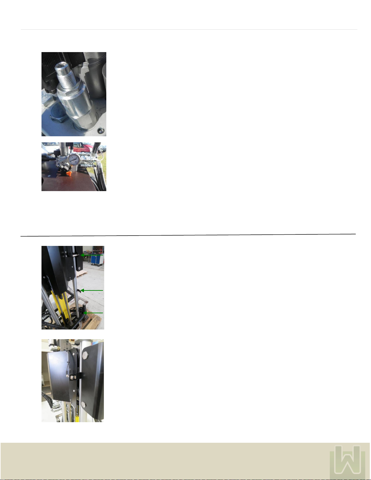
3. ADJUSTING THE DEPTH
The lower sensor plate defines the depth in program 1 and in program 2. Loosen the screws, and
move the sensor plate up or down to the desired depth.
The upper sensor plate defines where the soil sample in program 2 will be divided. The depth can be
adjusted from 0-30 cm. Loosen the screws, and move the sensor plate to the depth in which the soil
sample shall be divided.

P A G E | 4
Wintex Agro, Vilhelmsborgvej 8C, DK-7700 Thisted
+45 97990800, contact@wintexagro.com, www.wintexagro.com
The depth is infinitely variable, but pre-set from the factory at at 30 cm and 60 cm. The outer ruler shows the
full depth of the point where the sample will be collected. The inner ruler shows where the sample will be divided.
4. INTERRUPTING THE PROCESS
Due to various reasons it might be necessary to interrupt the process. In this case just deactivate the
foot switch, and the process will stop immediately. When reactivating the foot switch and the brake
handle at the same time, the probe will go back into start position. The soil will be discarded and not
filled into the soil boxes.
If the soil sampler is delivered with a remote control, the process will be interrupted by activating the
stop switch of the remote control instead.
5. REPLACEMENT OF O-RING, SCRAPER AND PROBE
Revolving platform
O-ring
Scraper
REPLACEMENT OF PROBE
Remove the soil box, and unscrew the six bolts with a 5 mm hex key. Both halves of the retainer
can now be removed.
Unscrew the three bolts. The revolving platform can now be pulled down along the probe.
Caution: The probe has sharp edges!

P A G E | 5
Wintex Agro, Vilhelmsborgvej 8C, DK-7700 Thisted
+45 97990800, contact@wintexagro.com, www.wintexagro.com
Remove the coupling nut with the special key which is delivered together with the WINTEX 2000.
It is now possible to remove the probe.
Coupling nut
Special key
REPLACEMENT OF O-RING
When the probe is removed, it is possible to replace the O-ring.
REPLACEMENT OF SCRAPER
At first force the spring roll pin out. Then replace the scraper and replace the old spring roll pin
with a new one.
6. ADJUSTMENT OF CHAIN FOR ROTATION
Loosen the four screws with a 4 mm hex key.
Then adjust the chain for rotation by turning the insex bolt (clockwise to tighten the chain, counter-clockwise
to loosen the chain. When the chain is adjusted correctly, the four screws must be tightened again. Use
a 4 mm hex key.

P A G E | 6
Wintex Agro, Vilhelmsborgvej 8C, DK-7700 Thisted
+45 97990800, contact@wintexagro.com, www.wintexagro.com
7. ADJUSTMENT OF CHAIN PROBE UP/DOWN
Move the probe approximately 20 cm down. Activate the emergency stop to stop the soil sampler,
and turn off the engine. The chain can now be adjusted by tightening the bolts.
8. ACTIVATING THE HYDRAULIC VALVES MANUALLY
Soil sampler up/down:
The soil sampler goes down when pressing the valve. The soil sampler goes up when pulling the valve.
Probe up/down:
The probe goes down when pulling the valve. The probe goes up when pushing the valve.
Rotation:
Screw counter-clockwise to activate the rotation process. Then press the main valve.
Important: Re-set the button into start position after use.
Do always activate the main valve by pressing it down when activating the other functions.
9. ADJUSTING THE HYDRAULICS
ADJUSTING THE MAIN PRESSURE
Start the motor with max. r.p.m. Press the main valve. The manometer must show 80-120 bar.
This valve is for adjusting the main pressure. The main pressure is pre-set on 120 bar. It must only be
adjusted after signing a written agreement with Wintex Agro.
Fuse: There is a 7.5 amp fuse for current control in the box and a 15 amp fuse for the oil cooler.

P A G E | 7
Wintex Agro, Vilhelmsborgvej 8C, DK-7700 Thisted
+45 97990800, contact@wintexagro.com, www.wintexagro.com
ADJUSTING THE PRESSURE OF THE SOIL SAMPLER TOWARDS THE GROUND
Open the lit of the electricity box.
Deactivate the emergency stop.
Adjust the Siemens logo:
Press “ESC”.
Press the downward arrow to “Set Param”.
Press ”Ok”.
Press the downward arrow until ”0n=”.
Move the cursor to change the numbers.
Larger numbers = higher pressure
Lower numbers = lower pressure
The pressure is from the factory pre-set at a proper pressure. Yet it might be necessary to adjust it
a bit so that the soil sampler stands firmly on the ground.
ADJUSTING THE ROTATION SPEED OF THE PROBE
Press the button down, and turn it counter-clockwise. The button will come up. Start the motor with
max. r.p.m. Press the main valve, and the probe will rotate.
Loosen the lock nut. The rotation speed is adjusted by turning the screw. When turning to the left, the
probe will move faster. When turning to the right, the probe will slow down. Adjust the screw until the
probe is set to 50 r.p.m.
Press the button down. Turn it to the left so that it stays down.

P A G E | 8
Wintex Agro, Vilhelmsborgvej 8C, DK-7700 Thisted
+45 97990800, contact@wintexagro.com, www.wintexagro.com
ADJUSTING THE PRESSURE OF THE PROBE
Loosen the lock nut. Adjust with a 6 mm hex key. Pressure will rise when turning to the right.
Lower the pressure by turning to the left.
Depending on the vehicle’s weight and the kind of soil, the pressure must be between 10 and 30 bar.
Read the pressure on this manometer, which only is for reading the pressure of the probe.
10. ADJUSTING AND MOUNTING THE SENSORS
The upper sensor plate determines if the probe is in top position.
The sensor plate in the middle determines where the soil sample will be divided..
The lower sensor plate determines the depth in which the soil sample will be taken.
The gap between both sensors and the sensor plates must be 2-3 mm. Make sure that the gap of both
sensors towards the sensor plates is exactly the same. It is recommended to adjust the sensors in relation
to the lower sensor plate.

P A G E | 9
Wintex Agro, Vilhelmsborgvej 8C, DK-7700 Thisted
+45 97990800, contact@wintexagro.com, www.wintexagro.com
You can see a light when the sensor is activated.
Make sure to connect the sensor and the sensor plug correctly by being aware of the notch.
11. PROTECTION AGAINST OVERHEATING
If the oil temperature exceeds 70OC, the electricity box will be temporarily disconnected, and the red
indicator light will be on. Wait until the temperature of the oil has lowered.
In extremely hot areas, or if the oil temperature would become a problem, shift to another oil type.

P A G E | 12
Wintex Agro, Vilhelmsborgvej 8C, DK-7700 Thisted
+45 97990800, contact@wintexagro.com, www.wintexagro.com
14. MAINTENANCE
Daily:
After three hours in use tighten all screws and bolts.
Check the chain for rotation. Lubricate if necessary.
Check the upper end of the probe. Lubricate if necessary.
Check the grease fitting for rotation. Lubricate if necessary.
Check all screws and bolts.
Clean the probe and the ejector.
Clean the soil box.
Clean the scraper blades.
Common cleaning of the soil sampler.
Check the level of the hydraulic oil and refill with oil if necessary.
Check the hydraulics for leaks.
Clean the oil tank.
Clean the oil cooler.
Check weekly and exchange/adjust if necessary:
50101038
Guiding rolls
16101022
Guiding pipe
16101002
Rotary sensor plate
50101044
Slide bearing
50101045
Gearwheel for rotation, 30 teeth
50101046
Gearwheel for rotation, 12 teeth
Check daily and exchange if necessary:
50101004
O-ring for scraper
50101003
Scraper
50101014
Scraper blade
50101039
Spring roll pin for scraper
16101001
Probe
Exchange after 500 hours in use and at least once a year:
10000002
Hydraulic oil filter
10000002
Hydraulic oil
Exchange if necessary:
15101196
Oil level rod with filter cap
Honda GX200 motor:
See instruction manual

P A G E | 13
Wintex Agro, Vilhelmsborgvej 8C, DK-7700 Thisted
+45 97990800, contact@wintexagro.com, www.wintexagro.com
15. PROBLEM SOLVING
PROBLEM
CAUSE
POSSIBLE SOLUTIONS
The WINTEX 2000 does not start soil
sampling.
1) The fuse is blown.
2) The emergency stop is activated.
3) The inner sensor is broken.
4) A switch is broken.
5) There is a gap between the inner
sensor and the upper sensor plate.
6) The hydraulic oil is overheated
(the red indicator light is on).
1) Replace the fuse with a new 7.5 amp fuse.
2) Deactivate the emergency stop.
3) Replace the sensor with a new one.
4) Replace the switch with a new one.
5) Adjust the upper sensor plate. The gap
should be 2-3 mm.
6) Wait until the oil has cooled down.
The soil sampler does not reach the ground
before the probe starts to move downwards.
1) There is too much oil supply, or the
oil viscosity is too high.
1) Change the oil, reduce the oil supply, or reduce
the rotation speed of the pump. Adjust the oil
pressure (r.p.m., manual point 7).
The hammer has no or too little power.
1) The probe is mechanically blocked.
2) The pressure accumulator is broken.
3) The hydraulic oil pump is broken.
4) The hydraulic oil filter is blocked.
1) Remove potential nicks. Lubricate the probe.
2) Replace the accumulator with a new one.
3) Replace the hydraulic oil pump with a new one.
4) Replace the hydraulic oil filter. The probe must
be able to move freely for 15-20 mm.
The probe does not rotate properly.
1) The push button on the rotation
valve is activated.
2) The sensors for rotation are not
adjusted correctly.
1) Deactivate the push button by pressing and
turning it clockwise. Then release the button.
2) Adjust the sensor. The gap should be 1-2 mm.
The probe gets stuck when moving upwards.
1) There are nicks/notches on the
probe.
2) The revolving platform is not
lubricated sufficiently.
1) Remove/repair the nicks. If there are notches,
mount a new probe.
2) Lubricate the revolving platform.
The oil gets overheated.
1) The fuse for the electric fan is
blown.
2) The thermostatic switch for the fan is
broken.
3) The cooling fins are blocked.
1) Exchange the 15 amp fuse in the electricity box.
2) Replace the thermostatic switch for the fan with
a new one.
3) Clean the cooler fins.
The soil sample is not divided correctly.
1)The gap between the outer sensor
And the sensor plate in the middle is
too wide.
2) The sensor in the middle is broken.
3) The gap between the outer and the
inner sensor and the lower sensor
plate is different.
1) Adjust the sensor plate in the middle. The gap
should be 2-3 mm.
2) Replace the sensor with a new one.
3) Adjust the lower sensor plate.

P A G E | 14
Wintex Agro, Vilhelmsborgvej 8C, DK-7700 Thisted
+45 97990800, contact@wintexagro.com, www.wintexagro.com
16. FAULT LOCATION HAMMER
Before starting locating faults, check that the oil flow from the power source is correct and that the pressure relief valve is set correctly.
PROBLEM
CAUSE
POSSIBLE SOLUTIONS
The hammer does not start.
There is pressure in hose P.
1) The oil supply goes to connection T
instead of connection P.
2) The striking piston is stuck in the
cylinder.
1) Switch hose P and hose T.
2) Polish or replace the components.
The hammer works irregularly.
1) There are impurities in the hydraulic
oil.
2) The oil level in the power source is
too low.
1) Replace the oil and the oil filter.
2) Add hydraulic oil.
The hammer performs badly.
1) There is an internal leak.
2) The oil flow from the power source
towards the hammer is incorrect.
3) The accumulator pressure is too low.
4) The return pressure is too high.
1) Dismount the valve housing and replace the
o-rings.
2) Check the oil flow.
3) Charge the accumulator with nitrogen or
replace it.
4) Check the power source, the hoses and the
filter.

P A G E | 15
Wintex Agro, Vilhelmsborgvej 8C, DK-7700 Thisted
+45 97990800, contact@wintexagro.com, www.wintexagro.com
17. DISMOUNTING THE ACCUMULATOR
Loosen the screws carefully with a 4 mm hex key.
Note: There are two screws in each hole.
Use a 3 mm hex key.
18. CONTROLLING THE ACCUMULATOR
Put a long rod down the hole the accumulator to check if the accumulator is
pressurized.
If the diaphragm can be pushed a lot, the accumulator must be charged with
Nitrogen or the diaphragm is defective.
In case of a defective diaphragm, the accumulator must be replaced
Loosen the charging screw with a 6 mm hex key.
If the accumulator is in order, you can hear a whistling sound of Nitrogen. In this
case merely recharge the accumulator.
If there is no whistling sound, the diaphragm is probably damaged and must be
replaced.

P A G E | 16
Wintex Agro, Vilhelmsborgvej 8C, DK-7700 Thisted
+45 97990800, contact@wintexagro.com, www.wintexagro.com
19. CHANGING OIL AND OIL FILTER
Plug the filling hole with a solid plug.
Remove both hoses.
Unbolt the engine and the tank.
.
Remember the bolt under the tank.
.
Slide the engine and the tank out under the cooler bracket and unbolt the engine.

P A G E | 17
Wintex Agro, Vilhelmsborgvej 8C, DK-7700 Thisted
+45 97990800, contact@wintexagro.com, www.wintexagro.com
Move the tank into an upright position. Unscrew the pump.
Replace the filter with a new one. Clean the tank thoroughly.
Then remount pump, tank and engine.
Interval
Type
Qty.
Adjustment
Check daily
Wintex 2000
Filler cap
5000 / 1 year
Wintex
Hydraulic oil
5000 / 1 year
EZ 46
7,5 / 4,5
X
Honda-motor
Valves
300 / 1 year
X
Air filter
100 / 1 year
Spark plug
100 / 6 month
BPR6ES
1
Motor oil
100 / 6 month
5w-30 / 10w-30
API-SJ or better
0,6
X
Table of contents
Popular Sampler manuals by other brands

Smith-Root
Smith-Root eDNA Sampler instruction manual

LumaSense technologies
LumaSense technologies Innova-1409 Service manual

OPFXS
OPFXS ASTEROIDE user manual

Sibata
Sibata HV-RW Operation manual

Endress+Hauser
Endress+Hauser Liquistation CSF48 Brief operating instructions

Teledyne
Teledyne 4700 Installation and operation guide