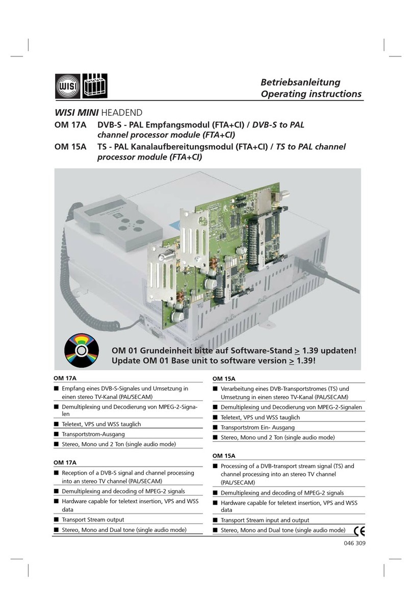
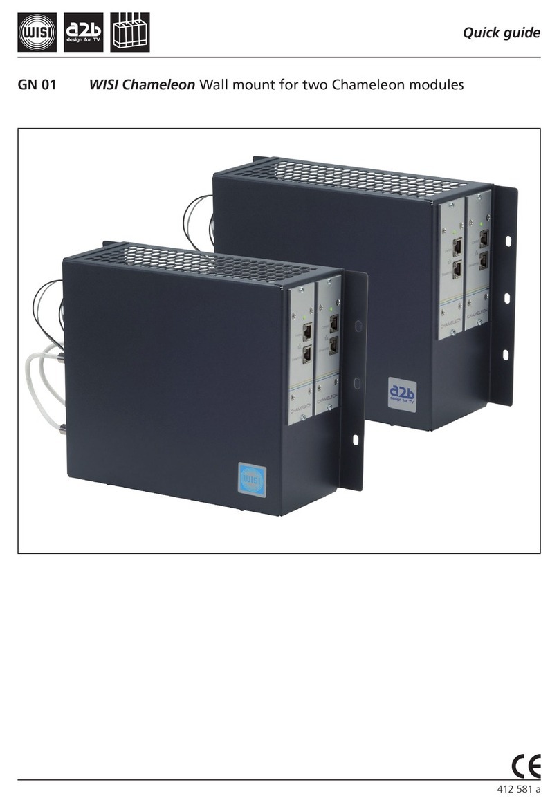
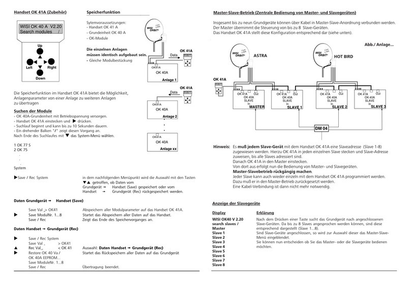
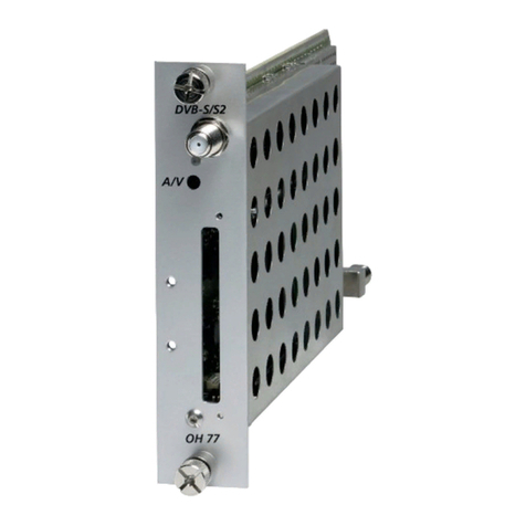
Wisi MINI OM 11 User manual

Betriebsanleitung
Operating instructions
05/05
WILHELM SIHN JR. GmbH & Co. KG
Empfangs- und Verteiltechnik
Wilhelm-Sihn-Straße 5-7, 75223 Niefern-Öschelbronn
Tel . 07233 / 66-292, Fax. 66-320, http://www.wisi.de
Technische Änderungen vorbehalten
Technical modifications reserved
044 852
Legende / Legend
FE = Front End
TS = Transport Stream
FTA = Free To Air
WISI MINI HEADEND
OM 11 DVB-T in Transportstrom(TS) Empfangsmodul (FE)
OM 11 DVB-T to Transport stream (TS) channel processor (FE)
Empfang eines DVB-T Signales 145 - 862 MHz
und Umsetzung in einen Transportstrom
Antennen-Eingang mit 5 VDC / 60 mA Speisung
Transportstrom-Ausgang
Reception of a DVB-T signal 145 - 862 MHz and
channel processing into an transport stream
Antenna input with 5 VDC / 60 mA power supply
Transport stream output
Technische Daten / Specifications
... a link to the future
Eingang / Input
Frequenzbereich / Frequency range 145-862 MHz
Eingangspegel / Input level 25 - 90 dBµV
QAM 64, 7/8 40 dBµV
QPSK, 1/2 25 dBµV
Kanalbandbreite / Channel bandwidth 7 / 8 MHz
Abstimmschritte / Tuning steps 500 kHz
Frequenz offset / Frequency offset 8 MHz ± 166,67 kHz
7 MHz ± 125,00 kHz
COFDM-Spektrum / COFDM spectrum 2k-FFT, 8k-FFT
Modulation QPSK, 16-QAM, 64-QAM
Schutzintervall / Protection intervall 1/4, 1/8, 1/16, 1/32
Fehlerschutz / Error correction 1/2, 2/3, 3/4, 5/6, 7/8
TS-Ausgang / TS output
Parallel Transportstrom-Ausgang
Parallel Transport stream output
Allgemeines / General data
Anschlüsse / Connectors
- Antennen-Eingang mit 5 VDC / 60 mA Antennenversorgung
- Antenna input with 5 VDC / 60 mA power supply
- TS-Ausgang / output LIF Anschluß für flexibles Folienkabel
LIF connector for flexible foil cable
- Betriebsspannung / Power supply PCB-Anschluß / PCB connector
Betriebsspannung / 3.3 VDC 150 mA
Power supply 5.0 VDC 300 mA
Leistungsaufnahme / Power consumption 2 W
Betriebstemperaturbereich / Operating temperature 0°C ... +55°C
Lagertemperatur / Storage temperature -25°C ... +75°C
Max. Luftfeuchte nicht kondensierend / 95 %
Max. humidity non condensing
Abmessungen / Dimensions 90 x 136 x 15 mm

OUT
470-862
MHz
IN-4
Netzteil
Power supply
Alimentation
IN-1
+5VDC
110mA
Module anschrauben
Tighten moduls 230 VAC
(A) (A)
Modul 1
IN-6
Modul 3
Modul 4
Modul 5
Modul 6
IN-2 IN-3 IN-5
Modul 2
Gain
Adj.
Einbau Module / Installation of moduls
Die zwei oberen Kreuzschlitzschrauben (A) am
Gehäusedeckel lösen und Deckel abnehmen.
Modul einsetzen, anschrauben und anschließen.
Deckel anschrauben und Einstellungen mit
Handset OK 41A vornehmen.
Loosen the two upper Philips screws (A) on the
cover and remove the cover. Insert the module,
screw it down and connect it. Fit and secure
the cover and make the necessary settings
with the handset OK 41A.
Werkseitige Einstellungen/ Factory settings
Ausgangsdämpfung / Output attenuator
0 dB
Spannungsfrei schalten!
Switch off power supply!
Anlagenbeispiele mit OM 11 DVB-T und OM 14 TS (FTA) Modulen
Sample system configurations with OM 11 DVB-T and OM 14 TS (FTA) modules
Module 1.......................................................6
OM 14 OM 14 OM 14 OM 14 OM 14
OM 11
TS Output
TS Durchschleifung
TS loop through
DVB-T
input
in
outout
in
Eingang / Input
TERR. VHF - UHF
(DVB-T)
OM 14 OM 14
DVB-T
input
OM 14
DVB-T
input
OM 11
OM 14 OM 14
OM 11
TS Output
OM 11
TS Output
OM 14
OM 11
DM 03
TS Durchschleifung
TS loop through
DVB-T
input
Module 1.....................3..... ....4......................6
Module 1.........2........ .3...........4........ ..5..........6
DVB-T
input
DM 02
OM 11
OM 14
DVB-T
input
DVB-T
input
DVB-T
input
DVB-T
input
in
out
in
out
in
out
in
out
Eingang / Input
TERR. VHF - UHF
(DVB-T)
Eingang / Input
TERR. VHF - UHF
(DVB-T)
Empfang von 5 Programmen aus einem Transponder /
Reception of 5 programs from one transponder
Empfang von 4 Programmen aus 2
Transpondern /
Reception of 4 programs from 2
transponders
Empfang von 3 Programmen aus 3
Transpondern /
Reception of 3 programs from 3
transponders
Hinweis: bei Teilbestückung, (z.B. 3 Module),darauf achten, daß der Modulplatz 1 bestückt ist, da über diesen
Modulplatz der Ausgangssammelverstärker mit Betriebsspannung versorgt wird.
Note: Please make sure that slot number one of the basic unit is equipped with a module (OM 14 or OM 16) in
any case (particularly if not all slots are to be used) because this first slot feeds the booster amplifier of the hole
unit with the necessary power.

Anschluß
Handset an Buchse einstecken.
Betriebsspannung anschließen.
Display zeigt Information: WISI OM Startup.
Ein zunehmender Balken zeigt den Initialisierungsvorgang an.
Beliebige Taste drücken. „Search modules“mit rotierendem„\“ erscheint.
Im Display erscheinen die gefundenen Module: 1 OM 14 CH 21
2 OM 14 CH 23
.
.
.
6 OM 11 (TS)
Bedienschritte auswählen
Tasten — Bedienschritt wählen.
Taste — Weiter zum Untermenü.
Taste — Zurück zum Hauptmenü .
Untermenü
Tasten — Anzeige oder zu ändernden Wert wählen.
Cursor steht unter dem Wert 89
Tasten — Wert ändern.
Handset OK... (Zubehör)
Parametereinstellung mit Handset
Left Right
Down
Up
WISI OMV1.20
Mi n i H e a d e n d
Bedienschritte Display Einstellungen
Lesen Sie vorher das oben stehende Kapitel „Bedienschritte auswählen“
Einzustellendes 1 OM 14 Ch 21 Mit UP/DOWN-Taste Modul wählen und mit R-
Modul 6 wählen 2 OM 14 Ch 23 Taste bestätigen.
.
.
6 OM 11 (TS)
Terrestrische- TerFrq Module 6 525,50 MHz Cursor_ mit L/R-Taste auf Dezi-
Eingangsfrequenz
(145-858 MHz)
malstelle schieben und mit
UP/DOWN-Tasten in 0,5-MHz-
Schritten einstellen.
Eingangs-Offset InOffs +125 kHz, 0, -125 kHz bei 7-MHz-Bandbreite
+166 kHz, 0, -166 kHz bei 8-MHz-Bandbreite
Mit UP/DOWN-Tasten auswählen und mit R-
Taste bestätigen.
Beispiel: 0,125 MHz + 525,50 MHz = 525,62-
MHz-Eingangsfrequenz
ZF-Bandbreite IF-BW OM 11 7 / 8 MHz
Signalrauschverhältnis InSNR >12 dB bei 16 QAM
(Anzeige) >18 dB bei 64 QAM
Legende: L/R-Taste =Left/Right
System-Einstellungen im Grundgerät OM 01 konfigurieren (V 1.20)
System-Einstellungen System settings Zu dieser Einstellung gelangt man über die Menü
wählen Punkte:
1 OM 14 Ch 21
2 OM 14 Ch 23
3 OM 14 Ch 25
4 OM 14 Ch 27
5 OM 14 Ch 29
6 OM 11 (TS)
System settings mit den UP/DOWN-Tasten.
Ausgangskanal Ch/Frq Ch21...69 / Mit UP/DOWN-Tasten auswählen
oder Frequenz 470-862 MHz und mit R-Taste bestätigen.
Ausgangsdämpfung OutAtt: 3 0...10 dB Cursor_ mit L/R-Taste auf Dezimalstel-
le schieben und mit UP/DOWN-Tasten
einstellen.
Software-Version Sw-Ver Mit UP/DOWN-Tasten auswählen und mit
Grundgerät (Anzeige) R-Taste bestätigen.
Hardware-Version Hw-Ver Mit UP/DOWN-Tasten auswählen und mit
Grundgerät (Anzeige) R-Taste bestätigen.
Die Speicherfunktion im Handset OK 41A bietet die Möglichkeit, Modulparameter von einem OM 01
zu weiteren OM 01 zu übertragen. Voraussetzung - gleiche Modulbestückung.
Hinweis:
Die Systemeinstellungen wie Ausgangskanal/Frequenz und Dämpfung werden nicht übertragen!
Save Settings Save :Set1...3 Set1...3 = Speicherplätze 1-3.
:Exit Speicherplatz-Nr. wählen und mit Taste „R“ -
bestätigen. Speichervorgang beginnt.
Exit = Zurück ins Hauptmenü
Recall Settings Recall :Set1...3
Speicherplatz 1...3 anwählen und mit „R“ bestätigen.
:Exit Restore from HS zeigt das Zurückspielen der
Parameter in OM 01 an.
Exit = Zurück ins Hauptmenü
Eingangs- BER InBER: 6.9 e-4 Die BER ist ein Mass für die Übertragungs-
Bit Error Rate fehler und damit für die Signalqualität.
(Anzeige) <1.0 e-4 = sehr geringe Fehler
1.0 e-3 = geringe Anzahl von Fehler
1.0 e-2 = kein Empfang - Anzeige: Signal?
Software-Version Sw-Ver Mit UP/DOWN-Tasten auswählen und mit
Modul (Anzeige) R-Taste bestätigen.
Hardware-Version Hw-Ver Mit UP/DOWN-Tasten auswählen und mit
Modul (Anzeige) R-Taste bestätigen.
Übertragungsrichtung
OM 01 OK 41A
Übertragungsrichtung
OK 41A OM 01

Connection
Plug the handset into socket .
Connect the supply voltage.
Display shows information WISI OM Startup.
A continuously bar shows the initialisation.
Press any button. „Search modules“with rotating „\“ is displayed.
Display shows the modules: 1 OM 14 CH 21
2 OM 16 CH 23
.
.
.
6 OM 11 (TS)
Operation selection
keys — Select Operation.
key — Open sub-menu.
key — Back to main menu.
Parameter sub-menu
keys — Select display or value to be changed.
Cursor stands under the value, e.g. 89
keys — Change the value.
Handset OK... (accessory)
Parameter settings with handset
Operation Display Settings
Remove to chapter „Operation selection“ first.
Select modul 6 1 OM 14 Ch 21 Select with UP/DOWN buttons and confirm
2 OM 14 Ch 23 with R button.
.
.
6 OM 11 (TS)
Terr. input frequency TerFrq Module 6 525,50 MHz Move cursor with L/R keys to
(145-858 MHz)
to digit to be changed and
adjust in 0.5 MHz steps with UP/
DOWN keys.
Input offset InOffs +125 kHz, 0, -125 kHz 7 MHz bandwidth
+166 kHz, 0, -166 kHz 8 MHz bandwidth
Select with UP/DOWN buttons and confirm
with R button.
Ex: 0,125 MHz + 525,50 MHz = 525,62 MHz
input frequency
If bandwidth IF-BW OM 11 7 / 8 MHz
Signal to Noise ratio InSNR >12 dB @ 16 QAM
(only displayed) >18 dB @ 64 QAM
Legend: L/R keys =Left/Right
Left Right
Down
Up
WISI OMV1.20
Mi n i H e a d e n d
Input BER InBER: 6.9 e-4 The BER is an indication of the number
Bit Error Rate of transmission errors and thus of the signal
(only displayed) quality.
<1.0 e-4 = very low numbers of errors
1.0 e-3 = low number of errors
1.0 e-2 = threshold for display: Signal?
Software version Sw-Ver Select with UP/DOWN buttons and confirm with
module (only displayed) R button.
Hardware version Hw-Ver Select with UP/DOWN buttons and confirm with
module (only displayed) R button.
System settings (set in basic unit OM 01 V 1.20)
System settings System settings Select with UP/DOWN buttons to „System
settings“.
1 OM 14 Ch 21
2 OM 14 Ch 23
3 OM 14 Ch 25
4 OM 14 Ch 27
5 OM 14 Ch 29
6 OM 11 (TS)
System settings
Output Channel / Ch/Frq Ch21...69 / Select with UP/DOWN buttons
Frequency 470-862 MHz and confirm with R button.
Output Attenuator OutAtt: 3 0...10 dB Move cursor with L/R keys to digit to
be changed and adjusted with UP/
DOWN keys.
Software version Sw-Ver Select with UP/DOWN buttons and confirm
basic unit (only displayed) with R button.
Hardware version Hw-Ver Select with UP/DOWN buttons and confirm
basic unit (only displayed) with R button.
The memory function of the handset OK 41A makes it possible to transfer modul para-meters from one
OM 01 to one or more other OM 01. Condition: All OM 01 must have identical modul configurations.
Note: The system settings like „Output Channel/Frequency and Output Attenuator are not transferred.
Save Settings Save :Set1...3 Set1...3 = Memories 1-3.
:Exit Select memory no. and confirm with „R“ -
button. Memory starts.
Exit = set to main menu
Recall Settings Recall :Set1...3 Select memory no.1...3 and confirm with „R“.
:Exit Restore from HS indicates recall function.
Exit = set to main menu
Transmission way
OM 01 OK 41A
Transmission way
OK 41A OM 01
Table of contents
Languages:
Other Wisi Control Unit manuals
Popular Control Unit manuals by other brands

Aksa
Aksa DSE 7320 AMF operating manual

Siemens
Siemens QAW850 operating instructions

Sloan
Sloan 152 ES-S TMO SWB installation instructions

Philio Technology Corporation
Philio Technology Corporation PAN03 manual

Agilent Technologies
Agilent Technologies 75000 SERIES B Configuration guide

Desin Instruments
Desin Instruments DAS-8000 quick guide