Wisi OL 16 1310 User manual

User Manual
OL 16 1310
Connecting past,
present and future. katalog.wisi.de
Optisches Verteilpaket
Optical Transmitter-Kit

User Manual – OL 16 1310 2
Deutsch
DKombiniert die SAT-Frequenzen des Breitband-LNB
mit den FM- /DAB- Radio und DVB-T/T2 Signalen.
Das IP65 spezifizierte Gehäuse ermöglicht eine Installation
am Ort der SAT-Antenne.
D3x HF Eingänge mit F-Anschlüssen (Radio/H/V)
D1x optischer Ausgang mit +7dBm (+-0.5 dB) Leistung
Auf einen Blick / At a glance
Überblick / Overview
OL 16 1310

User Manual – OL 16 1310 2
English
DCombines the satellite frequencies of the wide-
band LNB, FM-/DAB- Radio and signals from
a terrestrial antenna DVB-T/T2. The IP65 specified
housing ensures an installation at the dish location.
D3x RF Inputs with F connector (Radio/H/V)
D1x optical output with +7dBm (+-0.5 dB) power

User Manual – OL 16 1310 4
0
-25
+25
V H
Anschlüsse / Connections
1Wideband Output Vertical / Breitband Ausgang Vertikal
2Wideband Output Horizontal / Breitband Ausgang Horizontal
1
2

User Manual – OL 16 1310 4
1Optical Output FC/PC / Optischer Ausgang
2Terrestrial Input F type (+12V remote feed) /
Terrestrischer Eingang F Anschluss (+12V Fernspeisung)
3Wideband Input Vertical F type (+12V remote feed)
Breitband-Eingang Vertikal F Anschluss (+12V Fernspeisung)
4Wideband Input Horizontal F type (+20V remote feed)
Breitband-Eingang Horizontal F Anschluss (+20V Fernspeisung)
5Power in F-Type (+20V) / Eingang Spannungsversorgung F-Anschluss (+20V)
6LED Power On indicator / LED Betriebsanzeige
1
2
34
5
6

User Manual – OL 16 1310 6
Deutsch
Koaxial Anschlüsse
1. Die mit V oder H gekennzeichneten Anschlüsse sind mit dem
gelieferten Breitband LNB (WISI OC 07 E) zu verbinden.
Bitte achten Sie darauf, dass die richtigen Polarisationen an
die entsprechenden Anschlüsse angeschlossen werden.
2. Für die LNB-Versorgung wird eine Spannung von V = 12V,
H = 20V bereitgestellt. Maximaler Strom 500mA inkl. Terrestrik.
3. Der mit FM/DAB/DTT* gekennzeichnete Eingang ist mit den
geeigneten terrestrischen Antennen anzuschließen.
Die Signale sollten für eine optimale Leistung gefiltert und an-
gepasst werden.
4. Die am terrestrischen Eingang bereitgestellte Spannung be-
trägt 12V und ist für die Stromversorgung eines Mastverstärkers
vorgesehen.
5. Wird der terrestrische Eingang an ein Gerät angeschlossen,
das nicht für eine Spannung ausgelegt ist, sollte eine
Gleichstromsperre zwischen OL17 und dem Verstärker/Filter
installiert werden.
* DTT: Digital Terrestrial Television
Montageanleitung

User Manual – OL 16 1310 6
English
Coaxial Connections
1. Ports labelled V or H should be connected to a
suitable wideband LNB (recommended WISI OC07 E ).
Please make sure that correct polarisations are
connected to the relevant ports.
2. Voltage is supplied for LNB powering. V = 12V, H = 20V.
Maximum current 500mA inclusive terrestrial.
3. The input marked FM/DAB/DTT* should be connected
to your terrestrial antennas using an appropriate
combiner. Signals should be filtered and levelled for
optimum performance.
4. Voltage supplied on the terrestrial input is 12V
and is intended for powering a masthead amplifier.
5. If the terrestrial input is connected to a device not
designed for a voltage, then a DC block should be
installed between the OL17 and the device.
* DTT: Digital Terrestrial Television (DVB-T/T2)
Assembly instruction

User Manual – OL 16 1310 8
Deutsch
Optische Anschlüsse
1. Reinigen Sie die optische Ausgangsbuchse und prüfen Sie die
optische Leistung mit einem geeigneten optischen Leistungs-
messer. Die optische Leistung am Ausgang des OL17 ist +7dBm
±0,5dB betragen.
2. Reinigen Sie den optischen Stecker und stellen Sie eine Verbin-
dung zum optischen Ausgang von OL17 her, achten Sie dabei auf
die Ausrichtung der Nut.
3. Wichtig - Die mitgelieferte Gel Muffe sollte um den FC/PC-
Stecker geklippt werden, um einen Wetterschutz zu gewährleisten.
Die Lebensdauer kann beeinträchtigt werden, wenn diese nicht
angebracht wird.
Stromanschluss
1. Mit einem F-Stecker kann das OL17 mit Strom versorgt werden.
Das mitgelieferte 20V-Netzteil hat einen DC-jack/F Adapter.
2. Der Netzadapter ist für das Ausschalten des Gerätes vorgesehen.
Bitte stellen Sie sicher, dass dieser dauerha zugänglich ist.
3. Die LED an OL17 zeigt an, dass das Gerät korrekt mit Strom
versorgt ist. Die LED sollte konstant grün leuchten.
4. Maximale Stromaufnahme 350mA,
(ohne angeschlossene Eingänge)
Montageanleitung

User Manual – OL 16 1310 8
English
Optical Connection
1. Clean the output fibre optical connector and check the
optical power using a suitable optical power meter.
Optical power at the output of the OL17 is +7dBm ±0.5dB.
2. Clean the optical connecter and make a connection to
the optical output of the OL17, ensuring the keyway is
aligned.
3. Important - The gel mu supplied should be clipped
around the FC/PC connector to ensure weather protection.
Performance / operational lifetime may be affected if
the gel mu not fitted.
Power Connections
1. The OL17 can be directly powered at F connector
power input using a 20V PSU with the DC-jack to F adapter.
2. The mains adapter is the disconnect device for the unit.
Please ensure it is easily accessible.
3. LED on the OL17 indicates correct powering of the unit.
The LED should be constantly green.
4. Maximum current draw 350mA (excluding current on
connected inputs).
Assembly instruction

User Manual – OL 16 1310 10
Deutsch
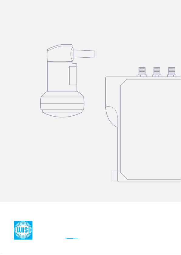
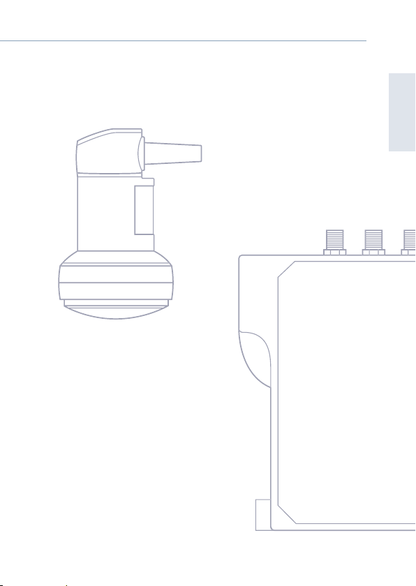
OL 17 1310 / Optischer Konverter
Eingang
Frequenzbereich SAT 290...2340 MHz
Impedanz 75 Ω
Rückflussdämpfung 20 dB (optisch)
Frequenzbereich DVB-T 470...694 MHz
Frequenzbereich DAB 174...240 MHz
Frequenzbereich FM 88...108 MHz
Pegelbereich 70...85 dBµV (Satellit); 70 dBµV
(Terrestrisch)
Welligkeit 1 dB 28 MHz
Verstärkung Vollband FM 88...108 MHz <1 dB; -DAB
174...240 MHz<1 dB; Terr. (DVB-T)
479...694 MHz <3...5 dB; SAT <=3
dB; Rejection @4G800 frequencies
791...862 MHz (relative)>30 dB
Anschluss TERR 1x F-female
Anschluss SAT 2x F-female
Ausgang
Wellenlänge 1310 nm (±20 nm)
Optische Leistung 7dBm +- 0.5dB
Anschluss FC/PC
Allgemeine Daten
Eingangsspannung 20 V DC (F-Connector)
Stromaufnahme max. 350 mA
(ohne angeschlossene Geräte)
Maximaler Upstream-Strom 500 mA
Ausgangsspannung Vertikal 12 V
Ausgangsspannung Horizontal 18 V
Betriebsumgebungstemperatur -20...+60 °C
Gewicht 0.445 kg
Abmessungen B x H x T 160 x 25 x 162 mm
Technische Daten
E/O Wandler
OL 17 1310

User Manual – OL 16 1310 10
Deutsch
Wideband LNB OC 07 E
Elektrische Daten
Eingangsfrequenz 10.70...12.75 GHz
Lokale Oszillatorfrequenz 10.41 GHz
Ausgangsfrequenz 290...2340 MHz
Verstärkung 50...62 dB
Rauschmaß typ. 0.5 dB
Verstärkung Vollband 7 dB (p-p)
Polarisationsentkopplung typ. -30 dB
Spiegelfrequenzunterdrückung 40 dB
Bandinternes Störsignal -60 dBm
L.O. Phasenrauschen @ 10 kHz -75 dBc/Hz
L.O. Temparaturschwankung
@ 25°C
±0,8 MHz
Ausgangsimpedanz 75 Ω
Mechanische Daten
Farbe dunkles grau, Pantone 432C
Feeddurchmesser 40 mm
Mit Schutzgehäuse Ja
Anschlüsse
HF-Ausgang 2x F-female
Allgemeine Daten
Ausführung Wideband
Teilnehmer Abhängig vom Multischalter
Multischalter integriert Nein
Terrestrische Einspeisung Nein
Eingangsspannung 8...21 V DC
Stromverbrauch max. 125 mA
Betriebstemperatur -30...+60 °C
Gewicht 0,445 kg
Abmessungen (B) 60 mm
Abmessungen (H) 60 mm
Abmessungen (T) 100.2 mm
Wideband LNB
OC 07 E

User Manual – OL 16 1310 12
English
OL 17 1310 / Optical Converter
Input
Frequency range-SAT 290...2340 MHz
Impedance 75 Ω
Return loss 20 dB (optical)
Frequency range DVB-T 470...694 MHz
Frequency range DAB 174...240 MHz
Frequency range FM 88...108 MHz
Level range 70...85 dBµV (Satellite); 70 dBµV
(Terrestrial)
Ripple 1 dB
Gain variation full band FM 88...108 MHz <1 dB; -DAB
174...240 MHz<1 dB; Terr. (DVB-T)
479...694 MHz <3...5 dB; SAT <=3
dB; Rejection @4G800 frequencies
791...862 MHz (relative)>30 dB
Connector DVB-T, DAB, FM 1x F-female
Connector SAT 2x F-female
Output
Wavelength 1310 nm (±20 nm)
Optical power 7dBm +- 0.5dB
Connector FC/PC
General data
Input voltage 20 V DC (F-Connector)
Current consumption max 350mA (excluding current on
the connected inputs)
Maximum upstream current 500 mA
Output Voltage Vertical 12 V
Output voltage Horizental 18 V
Operating temperature -20...+60 °C
Weight 0.445 kg
Dimensions W x H x D 160 x 25 x 162 mm
Technical Data
E/O Converter
OL 17 1310

User Manual – OL 16 1310 12
English
Wideband LNB OC07
Electrical data
Input frequency 10.70...12.75 GHz
Local Oscillator Frequency 10.41 GHz
Output frequency 290...2340 MHz
Gain 50...62 dB
Noise figure typ. 0.5 dB
Gain variation full band 7 dB (p-p)
Polarization isolation typ. -30 dB
Image rejection 40 dB
In band spurious level -60 dBm
L.O. phase noise @ 10 kHz -75 dBc/Hz
L.O. temperature dri @ 25°C ±0,8 MHz
Output impedance 75 Ω
Mechanical Data
Color Dark Grey, Pantone 432C
Feed diameter 40 mm
With protective enclosure Yes
Connectors
RF-Output 2x F-female
General data
Type Wideband
Subscriber Depending on the multiswitch
Integrated multi switch No
Terrestrial feed No
Input voltage 8...21 V DC
Current consumption max. 125 mA
Operating Temperature -30...+60 °C
Weight 0,445 kg
Dimensions (B) 60 mm
Dimensions (H) 60 mm
Dimensions (T) 100.2 mm
Wideband LNB
OC 07 E

User Manual – OL 16 1310 14
Mounting Dimensions
136.50 mm
4.95 mm
Ø 5.00 mm
4.30 mm
4.00 mm
81.74 mm

User Manual – OL 16 1310 14
0
43.8
88.0
24.2
Ø 60.0 Ø 40.0
100.2
38.9
25.9
50.0
-25
+25
-25 +25 +45-45 0
Phase Centre Position

© WISI Communications GmbH & Co. KG Technical Modifications reserved. WISI cannot be held liable for any printing error. 2023/01
WISI Communications GmbH & Co. KG
Installationsbeispiel
Installation example
Diese Verpackung enthält:
This Package contains:
Splitter OL91 xxxx
OL 17 1310
Power
Wideband LNB OC 07 E
Terrestrial
Optical
Coaxial
OL 16 Kit
H
V
Quad converter OL21
Quattro converter OL22
Opical fibre OL95
Multiwitch
Outlet
Outlet
OL 17 1310
E/O Wandler
E/O Converter
x1
OC 07 E
Wideband LNB
Wideband LNB
x1
20V DC Netzteil
20V DC Power
Supply Unit (PSU)
x1
Koaxialkabel
coaxial cable
x1
Gel Muffe
Gel mu
x1
Table of contents
Other Wisi Transmitter manuals
Popular Transmitter manuals by other brands

Burkert
Burkert 8138 operating instructions

Nautel
Nautel VS1 installation manual

RKI Instruments
RKI Instruments M2 Operator's manual

Mueller Systems
Mueller Systems Mueller Cellular Node installation manual

Micatrone
Micatrone Micaflex PD ver 4 Installation & operation manual

FOXEER
FOXEER VTX Reaper Infinity 5W manual