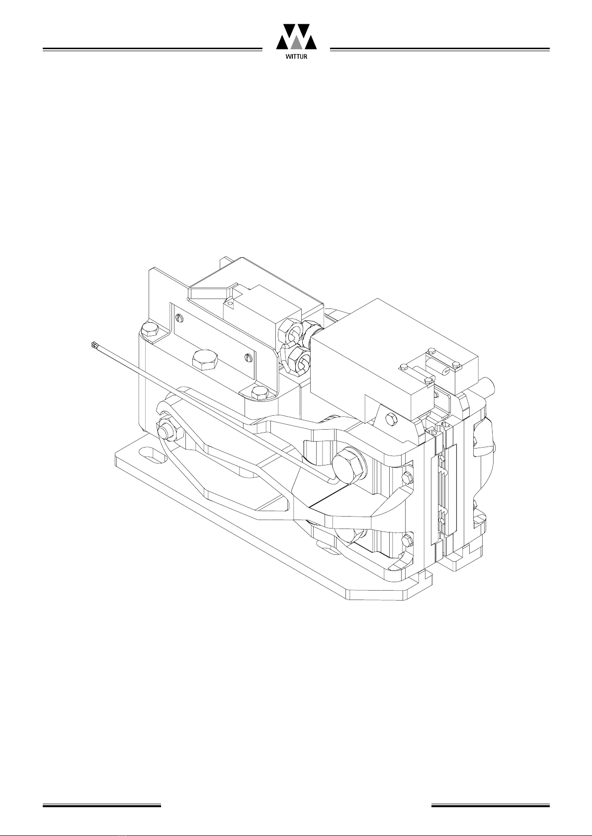
Braking System EBRA20
Operating instruction
Before starting installation work:
Only properly trained personnel may carry
out work, or be allowed access to the
installation site.
- Attach safety devices to guard against falling
(platform or harnesses)
- Cover any floor openings
- Secure installation tools or objects against
accidental falling
- Lift shaft openings should be cordoned off
and suitable warning signs should be erected
when working in shaft openings
- Work involving electrical equipment should
only be carried out by an electrical engineer or
qualified personnel.
1.4 Preparation
Before beginning installation work it is in your
own interest to ascertain the constructional and
spatial conditions. Where (workshop or on site)
and when which installation operations can or
must be carried out. It is recommended therefore,
taking into account all the given circumstances, to
plan the various operational sequences in advance,
rather than carrying them out prematurely and in
an unconsidered manner.
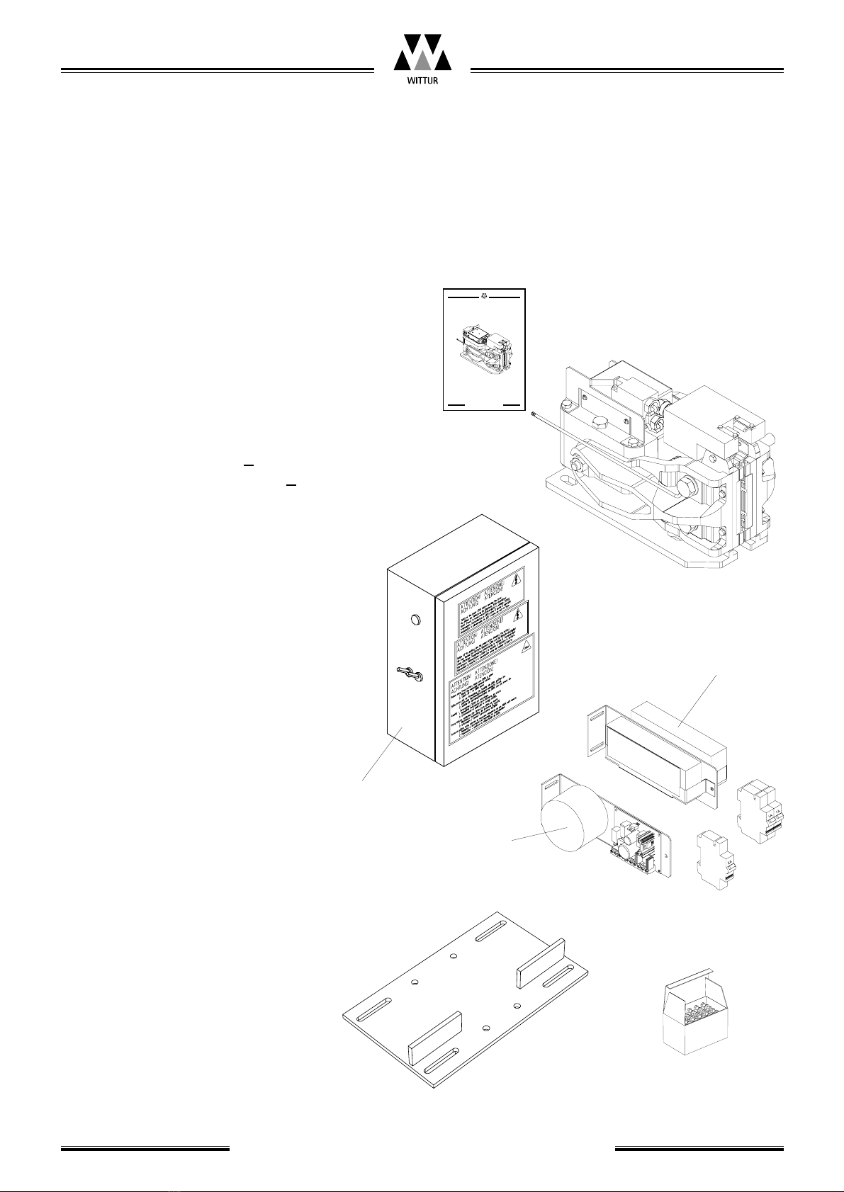
On receipt of the delivery, the goods or compo-
nents should be checked for correctness and com-
pleteness with the order sheet.
The following should be checked also:
- that the factory and order number correspond
- that the details on the name plate correspond
to those on the order
- the elevator speed
- the width and type of guide rail used
- the nominal load (Q)
1.5 Advice for when working on
safety components
The Brake system EBRA20 is classified as safety
components. It is most important that the stan-
dards and guidelines described in this section be
complied with as well as those given in the rest of
this operating manual.
These instructions, and especially the sec-
tion on safety precautions, should be read
and fully understood before work begins.
Safety devices require special attention. It is com-
pulsory that they function perfectly to ensure
danger free installation operation.
Safety devices that can only be adjusted after
installation should be done so immediately after
installation.
Operation of safety devices installed ex-works
must be tested immediately.
If it is necessary to disassemble a safety device
during servicing or repair, they should be reassem-
bled and comply with the required tests, as soon as
the work has been carried out.
Blatt/
sheet
D7AJMGB.004
Datum/
date
23.05.2002
Stand/
version
23.05.2002
Geprüft/
approved
WAT/MZE
THE LMC LIFTCOMPONENTS MANUFACTURING AND COMMERCE COMPANY
Änderungen vorbehalten! Subject to change without notice!