Blatt/sheet D550MGB.002
Datum/date 14.05.2001
Stand/version 14.05.2001
Geprüft/approved BRA/AD
Änderungen vorbehalten! Subject to change without notice!
THE LMC LIFTCOMPONENTS MANUFACTURING AND COMMERCE COMPANY
Hydraulic contact buffer
Operating instructions
1.1 Description and function
The hydraulic contact buffer type WHB is an
energy dissipation type buffer according to EN
81-1/2 and therefore can be universally used for
all applications in the construction of elevators.
The design type approval permits the use in pas-
senger and freight elevators both under the car
and under the counterweight.
Functional description (see fig. sheet 3)
In the case of a buffer stroke the piston rod (2) is
forced into the cylinder tube (1) and the hydrau-
lic fluid (3) in the tube is displaced and forced to
the outside through small throttling ports (4) in
the tube wall. The fluid accumulates within the
jacket tube (5).
At the same time the gas volume (6) above the
hydraulic medium is further compressed. The sea-
ling system (7) maintains a reliable seal between
the hard chromium-plated piston rod and the
atmosphere.
After the buffer stroke and return to hydraulic
balance the compressed gas volume forces the
displaced fluid back into the cylinder and extends
the piston rod.
The level of the hydraulic fluid at the gas interfa-
ce can be read at any time through the sight
glass (9) without opening the unit.
An elastic impact plate (16) damps the impact
and reduces the noise.
The limit switch (13) monitors the extended ready
position of the buffer. The limit switch is actuated
by pressure on the piston rod by the linear
slide (17) or the protection tube (10) respectively.
In the case of buffers equipped with a protection
tube (10), for maintenance work the screws (12)
on the buffer head (11) are removed. Subsequent-
ly, the protection tube can be lowered, which
simultaneously actuates the switch (13). The oil
filler screw (14) and the gas-filling valve (15) will
then be accessible.
In the normal operating state the protection tube
avoids damage and contamination of the piston
rod
1.2 Liability and guarantee
These operating instructions are intended for per-
sons who are familiar with the installation and
maintenance of lifts. Adequate knowledge of lift
construction is a prerequisite.
The WITTUR firm carries no responsibility for da-
mage caused by inpropriate or other actions un-
dertaken without adherance to these operating
instructions and thus compromising the qualities
of the product.
The warranty obligation of the WITTUR firm may
be inapplicable, if the component has been used
other than described in these instructions
Unless stated otherwise, the following are not
permissible due to technical safety reasons:
-installing the wrong buffer or one intended
for a different purpose according to these
instructions
-make changes of any kind to the hydraulic
contact buffers
furthermore
- carrying out faulty or improper maintenance,
maintenance or inspection checks and
- using unsuitable accessories, spare parts or
operating material which has neither been
released by the WITTUR Company nor consists
of original WITTUR spare parts.
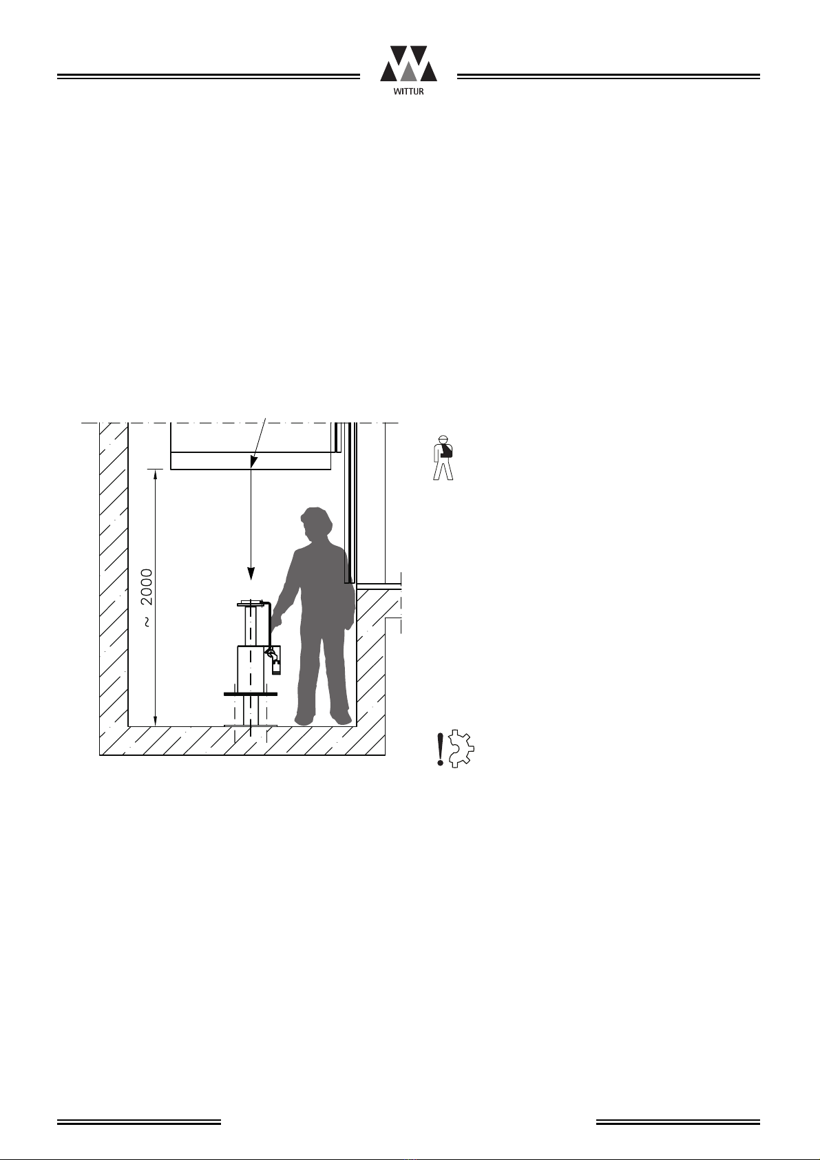
1 General information prior to installation