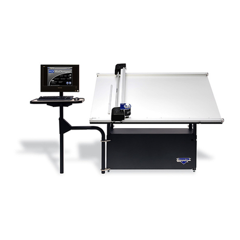
Wizard 8500e Parts list manual

CMC Model 8500e Rev 2
MatDesigner™Software
Getting Started Manual
8500e with SwitchBlade Technology
Revision E
MatDesigner™

2
Wizard™ International, Inc., 4600 116th St. SW, PO Box 66, Mukilteo, WA 98275 888/855-3335 Fax: 425/551-4350 wizardint.com
NOTES:

\Manuals\GettingStartedManual8500eRev2
10/02/08
3
MatDesigner™- Getting Started Manual - Model 8500e
MatDesigner™8500e - Getting Started
Manual
Contents
Packing List ................................................................................................7
Check Contents.........................................................................................................7
Equipment Required.................................................................................................7
Setting up the 8500e Board .......................................................................8
Setting up the Stand or Wall Mount..........................................................8
Assembling the Wall Mount................................................................................8
Assembling the Stand.........................................................................................8
Taking the Board out of the Box ...............................................................8
Black Protective Covering Sheet .....................................................................10
Unlocking the Shipping Blocks .............................................................................10
Unlock the Gantry Wheels...................................................................................... 11
Check Squareness..................................................................................................12
Check the Alignment Arrows............................................................................12
Check the Toothed Belt Lines ..........................................................................13
Head Installation.......................................................................................13
Install the Head onto the Gantry............................................................................13
Expose the Blade ....................................................................................................15
Installing the ST 500 Straight Line Trimmer...........................................16
Slide on the Straight Line Trimmer........................................................................16
Hooking up the Gantry and ST 500 Air Lines ........................................17
Connecting the Board Cable..................................................................................17
Calibration and Alignment of the Straight Line Trimmer......................19
Using the Straight Line Trimmer............................................................................19
Calibration and Alignment of the Straight Line Trimmer ....................................19
Install Hoods.............................................................................................21
Hook up Computer ...................................................................................21
Hook up Computer Peripherals .............................................................................21
Connect the ECU.....................................................................................................22

4
Wizard™ International, Inc., 4600 116th St. SW, PO Box 66, Mukilteo, WA 98275 888/855-3335 Fax: 425/551-4350 wizardint.com
Turn on the System ..................................................................................23
Turn on ECU ............................................................................................................23
Boot up the CPU......................................................................................................23
Conguration Diskette.............................................................................24
Design Your First Mat...............................................................................24
Edit New Mat............................................................................................................24
Opening Size......................................................................................................24
Borders...............................................................................................................25
Outside Size .......................................................................................................25
Layers .................................................................................................................25
Select Template..................................................................................................26
Go to Cut Preview to Cut Your First Mat ................................................26
Put Matboard on the CMC.................................................................................26
Click Cut .............................................................................................................27
Align the Head When Motors are Disengaged.......................................27
Align the Head.........................................................................................................27
After the CMC Has Cut the Mat.........................................................................28
If The Cut Doesn't Look Right ..........................................................................28
Changing the Blade..................................................................................28
Plunge Count .....................................................................................................28
Using the 45º Cartridge ..........................................................................................29
Changing the Blade...........................................................................................29
Using the 90° Cartridge ..........................................................................................30
Changing the Blade...........................................................................................30
Aborting a Cut...........................................................................................31
Restarting after an Abort........................................................................................31
Design a Different Mat..............................................................................32
Select a Different Template ....................................................................................32
Go to Cut Preview..............................................................................................32
Put Matboard on the CMC.................................................................................33
Click Cut .............................................................................................................33
Where to Find More Information .............................................................34
More information on the Straight Line Trimmer...................................................34
Documentation........................................................................................................34
Designing Multi Mats ..............................................................................................34
Website ....................................................................................................................34
Help - Context Sensitive Help ................................................................................34
Help Button on Menu Bar..................................................................................34
F1 for Help..........................................................................................................34

\Manuals\GettingStartedManual8500eRev2
10/02/08
5
MatDesigner™- Getting Started Manual - Model 8500e
Help Menu...........................................................................................................34
Help Screen .............................................................................................................35
Contents .............................................................................................................35
Index ...................................................................................................................35
Search.................................................................................................................36
Favorites.............................................................................................................36
Print.....................................................................................................................36
Troubleshooting .......................................................................................37
Cuts Look Wavy.................................................................................................37
Blade Keeps Breaking.......................................................................................37
Frequently Asked Questions...................................................................37

6
Wizard™ International, Inc., 4600 116th St. SW, PO Box 66, Mukilteo, WA 98275 888/855-3335 Fax: 425/551-4350 wizardint.com
NOTES:

\Manuals\GettingStartedManual8500eRev2
10/02/08
7
MatDesigner™- Getting Started Manual - Model 8500e
MatDesigner™8500e Getting Started Manual
8500e with SwitchBlade Technology
Packing List
If Shipped without a Computer:
Box 1: Mat Cutter (1) Wall Mount (If ordered; box is secured to the Mat Cutter box)
Box 2: AirRegulator/FittingHoses(1) BoxofBlades(1) CongurationDiskette
ECU (1) ECU to Board Cable (1) ECU USB Cable (1)
Gantry Covers (2) Getting Started Manual (1) Head Assembly (1)
Power Cable (1) Software (1) Debossing Kit
Tool Kit Allen Wrenches (3/32, 7/64, 1/8, 3/16, 5/32") Blade Cartridge (1)
If Shipped with a Computer:
Box 1: Mat Cutter (1) Wall Mount (If ordered; box is secured to the Mat Cutter box)
Box 2: Air Regulator/Fitting Hoses (1) Box of Blades (1) Computer (1)
ECU (1) ECU to Board Cable (1) ECU USB Cable (1)
Gantry Covers (2) Getting Started Manual (1) Head Assembly (1)
Keyboard (1) Monitor (1) Mouse (1)
Power Cord (3) Debossing Kit
Tool Kit Allen Wrenches (3/32, 7/64, 1/8, 3/16, 5/32") Blade Cartridge (1)
If Shipped with a Stand:
Box 3&4: Stand
If Shipped with a Computer Stand:
Box 5: Computer Stand
If Shipped with the ST 500 Straight Line Trimmer:
Box 6: ST 500 Straight Line Trimmer
Check Contents
Upon receipt of equipment, review for shipping damage and advise if any. Verify that contents shown above
are received. Note that only the items ordered will be shipped, therefore the number of boxes may be different.
Read this Manual before installing and operating the equipment. Save Packaging.
Equipment Required
Stand or Wall Mount - Must be Assembled First before unpacking the Wizard™ CMC
1/4"femalettingonmainairline,orquickdisconnectattachment
110 volt electrical outlet
Air Source - You will also need an air compressor that puts out between 100psi and 120psi.
Phone line, preferably a dedicated line
Surge Protector
Table for the Computer/Monitor

8
Wizard™ International, Inc., 4600 116th St. SW, PO Box 66, Mukilteo, WA 98275 888/855-3335 Fax: 425/551-4350 wizardint.com
*WARNING: The Wizard™ 8500e cannot be laid flat. It MUST be set on
a Stand or a Wall Mount to avoid damage to the Air Cylinders.*
Setting up the 8500e Board
CongratulationsontheacquisitionofyournewWizard™-welcomeaboard!TherststeptowardusingyournewWizardMat
Cutter is to set up your Stand or Wall Mount, then unpack the Wizard and install it. The following instructions will show you
how to set up your Wizard.
BeginbyclearinganareafortheWizard.Theboardrequiresatleast80" wide by 65" high (203 x 165 cm). The minimum
spacerequiredforthecomputer,monitor,mouseandkeyboardis26" x 30" (66 x 76 cm).
Setting up the Stand or Wall Mount
*The Stand or Wall Mount MUST be assembled before unpacking the
Wizard CMC, as you will be placing the Board immediately onto the
Stand/Wall Mount.*
Assembling the Wall Mount
If you purchased a Wall Mount, refer to the "Wizard CMC Wall Mount Assembly Instructions" in the box for assembly instruc-
tions. If the instructions are missing or any parts are missing, call Help Desk at 888/855-3335.
Assembling the Stand
If you purchased a Stand, refer to the "Wizard CMC Convertible Stand Assembly Instructions" in the box for assembly instruc-
tions. If the instructions are missing or any parts are missing, call Help Desk at 888/855-3335.
Taking the Board out of the Box
1.Withthehelpofasecondperson,placetheboxcarefullyonaatsurface.Cutthestrappingtape.Carefullyliftthecover
of the box away. With the help of a second person, carefully lift the Board straight up out of the box.
2. Have a third person remove the foam corners and move the box out of the way.
3. Position the Board onto the Wall Mount or Stand. Follow the instructions that came with the Wall Mount/Stand, and secure
the Board into place.
*Warning: Do not tilt the CMC against a wall, or place on a flat surface.
Damage to the Air Cylinders could occur.*

\Manuals\GettingStartedManual8500eRev2
10/02/08
9
MatDesigner™- Getting Started Manual - Model 8500e
4. Unscrew the two Air Lines on the bottom back of the Board, and make sure that the Air Lines on the back of the Board are
not pinched as you place the Board on the Stand. Reattach the Air Lines on the inside of the Stand Arms to ensure maximum
airow.
Fig A. Fig B. Fig C.
Fig A: Board in the Box. Fig B: Carefully lift the Board straight up from the box and remove foam corners. Fig C: Make
sure the Air Lines are not pinched between the Board and the stand.
5. Place the foam corners back into the box. Save packaging, foam corners and Shipping Blocks (removal instructions below)
for future use. See Contract Section 1, "Shipping Charges".
*NEVER SKIP AHEAD ON ANY STEP! Never pull/push on the Drive Shaft to
move the Gantry. Use the Gantry Arm.*
Fig D.
Fig D: Use the Gantry Arm to move the Gantry, not the Drive Shaft. The Drive Shaft is the thin cylindrical bar located
on the left side of the Gantry. The Gantry Arm is the rectangular housing on the right side of the Gantry.

10
Wizard™ International, Inc., 4600 116th St. SW, PO Box 66, Mukilteo, WA 98275 888/855-3335 Fax: 425/551-4350 wizardint.com
Black Protective Covering Sheet
The face of the CMC is covered by a black Sintra protective sheet. This is used to protect your CMC. Do not remove the
Sintra. You will add one disposable slip sheet of matboard between the Sintra and the mat you are cutting, to prevent damage
to the CMC.
Fig A. Fig B.
Fig A: Close up of the corner of the black Sintra. Fig B: Do not remove the black Sintra protective covering.
Unlocking the Shipping Blocks
1. Locate the four Shipping Blocks holding the Gantry in place. There are two on the upper Gantry (Fig A). One is to the left
of the Gantry on the underside of the top rail (Fig B) the other is to the right of the Gantry on top of the Rail (Fig C).
Fig A. Fig B. Fig C.
Fig A: Top shipping blocks. Fig B: Left top shipping block under top rail. Fig C: Right top shipping block above top rail.
The bottom shipping blocks are located on the top of the lower Rail on either side of the Gantry (Fig D-F).
Fig D. Fig E. Fig F.
Fig D: The lower shipping blocks. Fig E: Left lower shipping block. Fig F: Right lower shipping block.

\Manuals\GettingStartedManual8500eRev2
10/02/08
11
MatDesigner™- Getting Started Manual - Model 8500e
2. Remove the shipping blocks by loosening the 3/16” Allen screw from the T-Nut (Fig G-H). Remove the shipping blocks.
Slide the T-Nuts to the nearest end; a pencil eraser can make this easier (Fig I). Reattach the shipping blocks to the T-Nuts and
place in the shipping box for storage.
Fig G. Fig H. Fig I.
Fig G: Complete Shipping Block. Fig H: Remove 3/16" Allen screw from T-Nut. Fig I. A pencil eraser can be useful to
remove T-Nut from channel.
Unlock the Gantry Wheels
*IMPORTANT: DO NOT Operate the Wizard without first unlocking the
Gantry Wheels!*
1. The wheels on the Gantry are attached to a bar which is locked into place for shipping purposes. Locate the center Allen
Screw located at the bottom of the Gantry (Fig A); it is located between two other screws that will not be touched. Remove
the Allen Screw and the washer completely. DO NOT REMOVE THE OTHER SCREWS. You may hear/feel the Gantry
Wheels snap into place.
Fig A. Fig B.
Fig A: Locate Allen Screw at the bottom of the Gantry. Fig B: Do not touch the other screws.

12
Wizard™ International, Inc., 4600 116th St. SW, PO Box 66, Mukilteo, WA 98275 888/855-3335 Fax: 425/551-4350 wizardint.com
2. Now locate the center Allen Screw located on the top of the Gantry (Fig C); it is located between it is located between two
other screws. Note that the left screw is located behind the Drive Shaft, shown as a cut-away below. Remove the center Allen
Screw and the washer completely. DO NOT REMOVE THE OTHER SCREWS. You may hear/feel the Gantry Wheels snap
into place.
Fig C. Fig D.
Fig C: Locate Allen Screw at the top of the Gantry. Fig D: Remove Allen screw and washer.
3. Place the two Allen Screws and the washers you removed into the holes provided on the lower Gantry Plate (Fig E). These
multipurpose Allen Screws WILL BE USED during the lifetime of your Wizard, so it is important to place them here. Only
screw them in enough until the screw slightly protrudes from the back of the Plate.
Fig E.
Fig E: Place Allen Screws and washers into holes provided on the lower Gantry Plate.
Check Squareness
Check the Alignment Arrows
Check the small Alignment Arrows on left end of both the upper and lower Rails. Make sure they line up with the Alignment
Arrows on the Board itself (Fig A). If they do not, call Help Desk at 888/855-3335.

\Manuals\GettingStartedManual8500eRev2
10/02/08
13
MatDesigner™- Getting Started Manual - Model 8500e
Check the Toothed Belt Lines
Move the Gantry to the right and back. Looking at the upper Toothed Belt, slowly move the Gantry toward the right again until
youseearedlineontheToothedBelt.ConrmthattheredlinelinesupwiththeredlineontheToothedPulley(FigC).If
they don’t, call Help Desk. Without moving the Gantry, look at the lower Toothed Belt and make sure the red lines line up on
the Toothed Belt and the Toothed Pulley (Fig D). If not, call Help Desk.
Fig A. Fig B. Fig C. Fig D.
Fig A: Alignment Arrows on the bottom Rail. Fig B: Alignment Arrows on the top Rail. Fig C-D: Make sure the red lines
line up at the top and the bottom of the Gantry.
Head Installation
Install the Head onto the Gantry
*The Head is shipped with a Blade installed. Take care when handling
the Head so as to avoid injury.*
1. Remove the two 5/32" screws from the Head and set aside (Fig A). Move the Gantry to the right edge of the Board (Fig
B).
2. Point the Head so that the Foot Block faces toward the Board and the wheels are close to the bottom of the Gantry (Fig C).
Line up the wheels on the Head to the center channels of the Gantry arm. Ease the Head onto the Gantry (Fig D).
Fig A. Fig B. Fig C. Fig D.
Fig A: Remove screws from Head. Fig B: Move the Gantry to the right edge of the Board. Fig C: Line up Head wheels to
bottom of Gantry. Fig D: Ease Head wheels onto Gantry channels.

14
Wizard™ International, Inc., 4600 116th St. SW, PO Box 66, Mukilteo, WA 98275 888/855-3335 Fax: 425/551-4350 wizardint.com
3. Roll the Head up on the Gantry until it lines up to the Head Grabber Arm on the right side of the Gantry. (Fig E-F).
Fig E. Fig F.
Fig E: Head Grabber Arm. Fig F: Holes in Head and Head Grabber Arm lined up.
4. Hold the Head in position, and replace the two 5/32" screws, making sure they go into the Head Grabber Arm and into the
Head(FigG)thentightenrmly.MakesurethattheHeadandtheHeadGrabberArmlineuptogetherneatlytoensurecorrect
tting
5. Connect the Air to the Head by twisting the two Air Fittings together, matching colors (Fig H). Connect the Head Power
Plug(squareconnection)totheHeadGrabberArm(FigI).
Fig G. Fig H. Fig I.
Fig G: Screw in the two 5/32" screws, making sure they go into the Head Grabber Arm and into the Head. Fig H: Con-
nect the Air Lines, matching colors. Fig I: Connect the Head Power Plug.

\Manuals\GettingStartedManual8500eRev2
10/02/08
15
MatDesigner™- Getting Started Manual - Model 8500e
Expose the Blade
*The Head is shipped with a Blade installed. Take care when handling
the Head so as to avoid injury.*
1. Locate the yellow protective tape on the Foot Block covering the Blade (Fig A). Remove the tape from the Foot Block (Fig
B). The installed Blade is sharp.
2. Lift the Head up carefully from the Board as you roll the Gantry to the left so that the Foot Block does not strike the side of
the Board (Fig C).
Fig A. Fig B. Fig C.
Fig A: Locate yellow protective tape on the Foot Block and carefully remove the tape. Fig B: Close-up of the Blade.
Fig C: Lift the Head up carefully away from the Board as you roll the Gantry to the left to avoid striking the Foot Block
against the edge of the Board.
*WARNING: Do not run the Wizard without the Blade Cartridge in place
as the Blade Cartridge Release Lever could be damaged. *

16
Wizard™ International, Inc., 4600 116th St. SW, PO Box 66, Mukilteo, WA 98275 888/855-3335 Fax: 425/551-4350 wizardint.com
Installing the ST 500 Straight Line Trimmer
Slide on the Straight Line Trimmer
NOTE: A Blade has been installed, so take care when handling the Straight Line Trimmer.
1. Look at the backside of the Trimmer and locate the T-Nut on the glides (Fig A). Make sure that the T-Nut
lines up with the glide on both the upper and lower sections of the Trimmer.
2. Holding the Straight Line Trimmer steady (a second person helps here), carefully slide the Trimmer onto the
channels on the right side of the Board, making sure that the T-Nuts slide into the channel of both the upper and
lower rails (Fig B). Move the Straight Line Trimmer to the left until it stops (Fig C).
Fig A. Fig B. Fig C.
Fig A: Make sure the T-Nut lines up to the glide. Fig B: Carefully slide Trimmer onto the channels on the right side of
the Board. Fig C: Slide Trimmer until it stops.
Lock the Straight Line Trimmer in Place
1. Slowly tighten the bottom locking knob COUNTER-CLOCKWISE until it is snug (Fig A).
2. Slowly tighten the top locking knob CLOCKWISE until it is snug. You will calibrate it after the air lines are
hooked up (Fig B).
Fig A. Fig B.
Fig A: Turn bottom knob Counter-Clockwise. Fig B: Turn top knob Clockwise.

\Manuals\GettingStartedManual8500eRev2
10/02/08
17
MatDesigner™- Getting Started Manual - Model 8500e
Hooking up the Gantry and ST 500 Air Lines
Connecting the Board Cable
*Be VERY CAREFUL when connecting the large Board Cable. Align the
four in-line pins carefully before applying pressure to plug them in. If
forced in incorrectly, they WILL cause malfunction of the Wizard Mat
Cutting system.*
1. The Board Cable connects between the ECU (Electrical Control Unit) and the Gantry. The ECU is the black shoebox-sized
peripheral with a row of LEDs. Connect the large Board Cable (Fig A) to back of the ECU (Fig B) by aligning the four in-line
pins and turning the locking ring until it “seats itself” and locks into place.
2. Connect the other end of the Board Cable to the back of the Gantry in the same manner (Fig C).
3. Move the Gantry to the far right of the Board and back to make sure the Board Cable does NOT get caught on anything. If
the Board Cable is obstructed, this WILL affect your cuts.
Fig A. Fig B. Fig C.
Fig A: Look for the 4 in-line pins on Board Cable. Fig B: Plug one end into back of the ECU. Fig C: The other end is
plugged into the back of the Gantry.
Attaching Air Lines and Air Regulator
1. Go back and make sure that the Air Lines on the back of the Board are not pinched between the Board and the Stand. If you
havenotalreadydoneso,reattachtheAirLinesontheinsideoftheStandArmstoensuremaximumairow(FigA).
2. Connect the Blue Connector from the top of the ST 500 to the Blue Connector/Shut Off Valve of the "Y" Connector (Fig
B).
3.ConnectRedConnectorfromthetopoftheGantrytotheRedConnectorof"Y"Connector;onlyonesidewillt.
NOTE: If you did not install the SL 500, this Red Air Line Connector from the Gantry would plug
into the right side of the Air Regulator.
4. Plug in the Red Air Line Connector from the bottom of the "Y" into the right side of the Air Regulator.
5. Plug the Air Line coming off the left side of the Air Regulator into your main air supply via 1/4" NPT female connector, or
thequickdisconnect,whichevertypeyoupurchased(shownistheblackthreadedttingconnectedtoa1/4"NPTfemaleadap-
tor).Youraircompressorshouldhaveatleast100-120PSI.ItissuggestedthatTeontapebeusedonthethreadsoftheblack
ttingtoreducepossibleairleakage.
6. Strap your Air Regulator, glass bowl down to the left large wall bracket or left stand side with cable ties provided in your
Tool Kit, making sure not to crimp any of the Air Lines.

18
Wizard™ International, Inc., 4600 116th St. SW, PO Box 66, Mukilteo, WA 98275 888/855-3335 Fax: 425/551-4350 wizardint.com
7. Connect Blue Connector from the top of the Gantry to the Blue Connector on the back of the Board.
8. Turn on the Air.
Fig A. Fig B.
Fig A: Connect bottom Air Lines to the interior of the Stand Arms. Fig B: Connect Blue Connector on the ST 500 to
Blue Air Connector of the “Y” Connector. Connect Red Connector of Gantry to top Red Connector of "Y" Connector.
Connect bottom Red Connector of "Y" Connector to right side of Air Regulator. Attach left side of Air Regulator to air
source. Connect Blue Connector from the Gantry to the Blue Connector on the back of the Board.
*WARNING: The Air Regulator comes factory-set. Do not make any
adjustments to it.*

\Manuals\GettingStartedManual8500eRev2
10/02/08
19
MatDesigner™- Getting Started Manual - Model 8500e
Calibration and Alignment of the Straight Line Trimmer
Using the Straight Line Trimmer
*Do not press down on the Trimmer Handle while moving in an upwards
direction, or you will break the Blade.*
1. Place at least one piece of matboard larger than the mat being trimmed behind the Straight Line Trimmer to
avoid cutting into the Board.
2. Place the matboard to be cut underneath the Straight Line Trimmer; use the handy ruler for placement.
3. Flip the clamp switch upwards to lock the matboard down (Fig A).
4. Raise the handle and pull upwards to bring the cutting assembly to a position above the mat to be cut (Fig
B).
5. Press down on the handle and pull downwards (Fig C).
6. Flip the clamp switch downwards to unlock the matboard, and remove the matboard.
Fig A. Fig B. Fig C.
Fig A: Flip the clamp switch upwards to lock the matboard. Fig B: Lift handle and raise above mat to trim. Fig C: Press
down on handle and pull downwards
Calibration and Alignment of the Straight Line Trimmer
Trim a Mat
Place a piece of matboard at the 10” mark, and using the Trimmer, trim it (Fig A). Measure the width of the mat-
board. If it does not measure 10” across the top and across the bottom, the Trimmer needs to be calibrated.
Calibrate the Bottom of the Straight Line Trimmer
1. Start with the bottom. Loosen the bottom Locking Knob by turning it Clockwise (Fig B).
2. Using a 7/16” Open-Ended Wrench, loosen the Locking Nut (see Arrow in Fig C).
3. Using a 3/16” Allen Wrench, turn the Alignment Adjustment Screw Clockwise to move the Trimmer to the
Right; turn it Counter-Clockwise to move the Trimmer to the left (Fig C). When moving to the Left, you will need
to push the Trimmer to the Left so that the Alignment Adjustment Screw stays on contact with the rail.
4. Tighten the bottom Locking Knob by turning it Counter-Clockwise.

20
Wizard™ International, Inc., 4600 116th St. SW, PO Box 66, Mukilteo, WA 98275 888/855-3335 Fax: 425/551-4350 wizardint.com
5. Cut the mat again... remember we are looking at the bottom of the mat. When the bottom of the matboard
cuts the correct width, retighten the Locking Nut (Arrow in Fig C) to keep the Alignment Adjustment Screw from
moving.
Fig A. Fig B. Fig C. Fig D.
Fig A: Trim a piece of matboard and measure. Fig B: Turn bottom lock knob Clockwise. Fig C: Locking Nut, and ad-
justing Alignment Adjustment Screw. Fig D: Turn bottom lock knob Counter-Clockwise.
Calibrate the Top of the Straight Line Trimmer
1. Trim a tall piece of matboard at 10” and measure across the top and across the bottom. If it does not measure
10” across the top and across the bottom, continue.
2. Loosen the top locking knob by turning it Counter-Clockwise.
3. Using a 7/16” Open-Ended Wrench, loosen the Locking Nut (see Arrow in Fig B).
4. Turn the Alignment Adjustment Screw Clockwise to move the Trimmer to the Right; turn it Counter-Clockwise
to move the Trimmer to the Left (Fig B). When moving to the Left, you will need to push the Trimmer to the Left
so that the Alignment Adjustment Screw stays on contact with the rail.
5. Tighten the top locking knob by turning it Clockwise (Fig C).
6. Cut the mat again, and readjust if necessary. When the top of the matboard cuts the correct width, retighten
the Locking Nut (Arrow in Fig B) to keep the Alignment Adjustment Screw from moving.
Fig A. Fig B. Fig C.
Fig A: Turn top lock knob Counter-Clockwise. Fig C: Locking Nut, and adjusting Alignment Adjustment Screw. Fig D:
Turn top lock knob Clockwise.
*Do not use the Wizard to cut anything wider than 53” from the left
edge of the matboard... this INCLUDES the outside cut... without first
removing the Straight Line Trimmer.*
Table of contents
Other Wizard Cutter manuals