http://www.facebook.com/OlympiaElectronics
http://twitter.com/olympiaelectro
http://www.linkedin.com/company/1967613?trk=tyah
http://www.youtube.com/channel/UCIINc4DGSYH_0loHJqwsgoQ
https://plus.google.com/105672704483774116420/posts
http://www.olympia-electronics.gr
GENERAL
BS-695 and BS-694 detectors are used to give
us a quick warning in case there is a natural gas
or LPG gas leak.
The installation must be done by a qualified
personnel. The instructions must be read first
before the installation.
Emergency actions
It is recommended that the following advice
should be given in the event of an alarm
sounding or the smell of gas even without an
alarm:
Keep calm, and carry out the following actions,
not necessarily in the order given:
- extinguish all naked flames, including
smoking material.
- turn off all gas appliances.
- do not switch on or off any electrical
equipment, including the gas detection
apparatus.
- turn off the gas supply at the gas main control
and/or ( with a LPG supply) the storage tank.
- open doors and windows to increase
ventilation;
- do not use a telephone in the building where
the presence of a gas is suspected.
If the alarm continues to operate, even after an
alarm resetting action where appropriate, and
the cause of the leak in not apparent and/or
cannot be corrected, vacate the premises and
IMMEDIATELY NOTIFY the gas supplier in
order that the installation may be tested and
made safe, and any necessary repair carried
out.
Placement
Depending on the monitored gas, the unit must
be placed 30cm from the ceiling (for methane,
natural gas) or 30cm from the floor (for propane,
butane, LPG). The horizontal distance should
not be more than 4 meters from the probable
gas leak point and the detectors must not be
placed in humid or drafty areas.
It is suggested that the detector is tested for
good operation every 6 months or if it is
changed position.
The unit must should not be sited:
- directly above cooking appliances.
- directly above sink.
- adjacent to extractor fans.
- in any outside location.
- where the environmental conditions are
outside the manufacturers operational
specification.
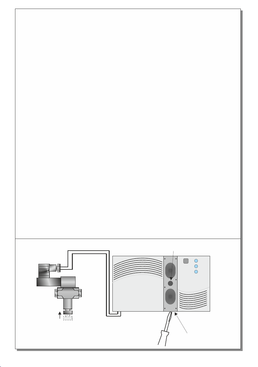
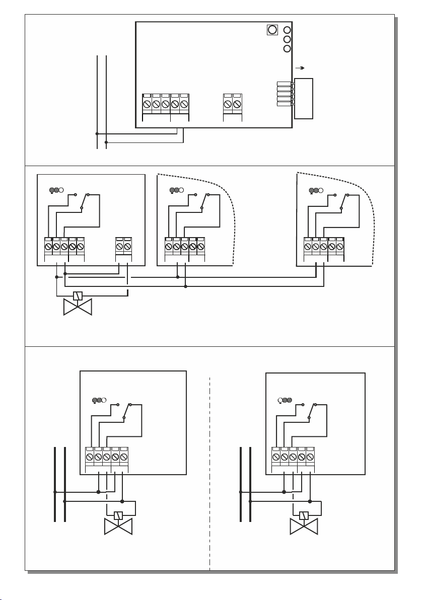
Installation
For the installation of the device first you must
remove the red plastic with a screwdriver as
shown in figure 1 and unscrew the screw in the
middle. Then with the help of figure 2 you can
connect the external devices.
Sensitivity
The BS-694 detectors are activated when the
220-240V AC/50-60Hz
Yes Yes
Relay (230V AC, 5Α)
Power LED , alarm LED , fault LED
IP40
5 years
EN 50194, EN 61000-3-2, EN 61000-3-3
o
0 to 60 C
Up to 95%
No No
5-15 % L.E.L. Propane 5-15 % L.E.L. Methane
145 x 85 x 45 mm
Bayblend FR3010
BS-694 BS-695
4VA
TECHNICAL CHARACTERISTICS
OPERATION TEMPERATURE RANGE
RELATIVE HUMIDITY
CONSTRUCTION MATERIALS
EXTERNAL DIMENSIONS
TYPICAL WEIGHT
GUARANTEE
OPERATION VOLTAGE
AVERAGE POWER CONSUMPTION
SENSITIVITY
OUTPUTS
ELECTRO VALVE OUTPUT
EXTERNAL BUZZER OUTPUT
SENSOR LIFETIME
INDICATIONS
DEGREES OF COVER PROTECTION
PRODUCED IN ACCORDANCE WITH
2 years
270gr.
BS-694 Autonomous LPG detector
BS-695 Autonomous natural gas-methane detector
Page 1 from 4
Thank you for your trust in our products.
Olympia Electronics - European manufacturer.
921695000_09_009