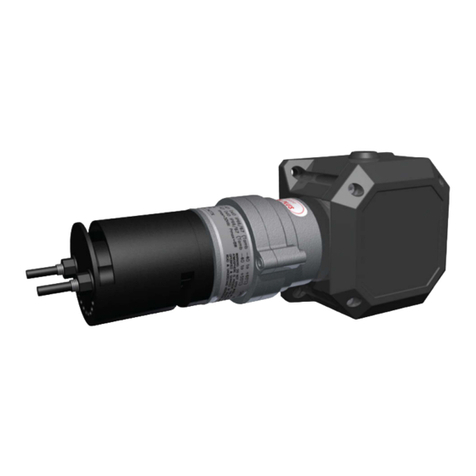
Consilium Salwico KVD User manual

Gas Detector
$,7B4.:'
(
)
Specifications may be subject to change for improvement without prior notice Data sheet no: 3242.01.1.E
H:9>474@8 Consilium Marine AB
P.O. Box 8763, SE-402 76 Göteborg
Phone +46 31 7107700 Fax +46 31 7107800
www.consilium.se
Part no. 3242
System: Gas Alarm System
Description
KVD is a group name for detectors in the Salwico gas alarm
programme for detection of explosive, toxic or inflammable
fluids and gases. KVD detectors are intended for use in
heavy-duty industrial environments and can be adapted for
detection of different gases depending on which semi-
conductor sensor it is equipped with.
The KVD detector consists of an aluminium junction box and
a sintered housing around the sensor. The KVD is connected
to the central unit via a screened 3-core cable.
KVD(COD) is intended for detection of carbon monoxide
(CO). The KVD(COD) also includes a dust filter to minimise
interference from other gases.
Technical data
Cable connection to See connection diagram
gas alarm central for gas detector
Enclosure protection IP-54
Cable entry 6 - 11 mm
Temperature range -40° - +85°C
Relative humidity 0 - 95%
Material connection box Varnished aluminium
Weight 350 g
Colour Grey box with nickel-
plated sintered housing
Dimensions (mm)
Connection
111
53
75 86

Gas Detector
BUTOX ST400EC
Part no. 4461 O
2
4462 H
2
S
4463 CO
System: Salwico GS3000, SW2020
Description
The BUTOX ST400EC gas detector to measure oxygen,
toxic or flammable gases consists of a chrome plated
ABS-housing with transmitter print, sensor and sensor
holder in stainless steel.
The transmitter print is based on the “one man
calibration” technology. This means that one person can
make all the necessary calibrations inside the detector
head, without the necessity of a second calibration
procedure on the measurement module.
Measuring Range
Specifications may be subject to change for improvement without prior notice Data sheet no: 4461 04 1 E
ÇConsilium
Consilium Marine AB
P.O. Box 8763, SE-402 76 Göteborg
Phone +46 31 7107700 Fax +46 31 7107800
CO 0-250 ppm
H
2
S 0-30 ppm
O
2
0-25 %
Sensors for other toxic gases are available upon request.
Data
Weight ~470 g
Material housing Chrome plated ABS
Sensor housing SS 316
Power supply 12-30 VDC
Signal 4-20mA (2-wire)
Sensor 2- or 3-electrode
Measuring principle Electrochemical cells
Temperature range -40°C to +60°C
Protection class IP65 (excl. sensor)
Cable entry Od Ø 8-13.5 mm
Optional certificate class* EEx ia IIC T6,
T
amb
-40°C to +60°C
*If used with a specified safety barrier.
Dimensions (mm) Connection
Mounting holes
110
43
145
122
172
120
90
55
www.consilium.se

Gas Detector
BUCOM ST600EX
Part no. 4460
System: Salwico GS3000, SW2020
Description
The BUCOM ST600EX gas detector for combustible
gases is assembled with an EExd sensor, housing and
cable gland.
The transmitter is based on the so-called “one man
calibration” principle, which means that the calibration
takes place at the detector head only.
The sensor is a replaceable catalytic oxidation sensor and
consists of detection and reference elements that are
provided in a wheatstone bridge. When exposed to gas,
the bridge will be unbalanced and an electric signal
proportional to the gas-concentration will be converted to
a 4-20mA output signal.
Sensors for other explosive gases are available upon
request.
When installing BUCOM ST600EX in ventilation ducts,
the air duct mounting kit part. no. 4490 shall be used, see
separate drawing.
Data
Weight 2.8 kg
Material housing Steel coated
Sensor housing SS 316
Power supply 18-35 VDC
Power consumption 1.7 W
Output signal 4-20mA (3-wire)
Response time t90 < 15sec.
Sensor lifetime Min. 3 years in air
Measuring principle Catalytic
Measuring range 0-100% LEL
Temperature range -20°C to +60°C
Protection class IP65 (excl. sensor)
Cable entry Od Ø 10-16 mm
Ex class EEx-d IIC T6
Certificate KEMA No. Ex.99.E.1378
Cable spec. Shielded, min. 3x0.75mm
2
Cable resistance Max 100Ωat 24VDC
Max 200Ωat 30VDC
Specifications may be subject to change for improvement without prior notice Data sheet no: 4460 04 1 E
ÇConsilium
Consilium Marine AB
P.O. Box 8763, SE-402 76 Göteborg
Phone +46 31 7107700 Fax +46 31 7107800
Dimensions (mm) Connection
Mounting holes
194
183 81
76
Ø7
www.consilium.se

çConsilium
Gasdetektor
Salwico KVD-Ex
KVD-Ex är en detektor ingående i Salwico
gaslarmsprogram för detektering av
explosiva, giftiga och brännbara vätskor
och gaser. KVD-Ex är avsedd för tuff inom-
eller utomhusmiljö och den är godkänd för
installation i Ex-klassade områden, zon 1
eller motsvarande. KVD-Ex anpassas för
detektering av olika
gaser genom att den kan bestyckas med
olika halvledarsensorer.
KVD-Ex består av en kopplingsdosa av
polyester och ett sensorhus av rostfritt stål.
KVD-Ex är typgodkänd av Nemko.
u9090303.DOC 1(2)

çConsilium
CONSILIUM SECURITY SYSTEMS AB
P.O. Box 8763
SE-402 76 GÖTEBORG
SWEDEN
Besöksadress:
Salsmästaregatan 21
Ringön
GÖTEBORG
Telefon:
Nat 031-710 79 00
Int +46 31 710 79 00
Telex:
20660 consmar s Telefax:
Nat 031-710 79 99
Int +46 31 710 79 99
Dimensioner (mm)
Anslutningar
Data
Kabelförbindning med
gaslarmscentral Se separat
inkopplingsschema Material sensorhus Rostfritt stål
(SIS2343)
Kapslingsgrad
kopplingsdosa IP-65 Mätprincip Halvledare
(Figaro TGS)
Kabelgenomföring 10 – 15 mm Ex-skyddsklass EEx de IIC T6
Temperaturområde -40 - +85 Vikt 900 g
Relativ fuktighet 0 – 95% Färg kopplingsdosa Svart
Material kopplingsdosa Polyester Färg sensorhus Blank metall
Artikelnummer 3122
*) Hela detektorn håller IP-65 om den förses med speciellt stänkskydd för sensorhus. Se separat ritning.
u9090303.DOC 2(2)

çConsilium
Gas Detector
Salwico KVD-Ex
KVD-Ex is a detector type included in the
Salwico gas alarm program for detection of
explosive, toxic and inflammable fluids and
gases. KVD-Ex is intended for heavy
environments, both indoors and outdoors
and is approved for installation in Ex
classified areas.
KVD-Ex can be adapted to detect different
gases when equipped with semiconductor
sensors.
KVD-Ex consists of a junction box of
polyester type and a sensor housing of
stainless steel type.
KVD-Ex is type approved. u9090302.DOC 1(2)

çConsilium
CONSILIUM MARINE AB
P.O. Box 8763
SE-402 76 GÖTEBORG
SWEDEN
Visiting address:
Salsmästaregatan 21
Ringön
GÖTEBORG
Telephone:
Nat 031-710 77 00
Int +46-31 710 77 00
Telex:
20660 consmar s Telefax:
Nat 031-710 78 00
Int +46 31 710 78 00
Dimensions (mm)
Connection
Data
Cable connection to
central panel See separate connection
diagram no. Sxxx319 Material sensor housing Stainless steel
(SIS2343)
Enclosure protection
junction box *) IP-65 Measuring principle Semi-conductor
(Figaro TGS)
Cable connection 10 – 15 mm Ex protection class EEx de IIC T6
Temperature range -40 - +85 Weight 900 g
Relative humidity 0 – 95% Colour junction box Black
Material junction box Polyester Colour sensor housing Metal
Part no 3122
*) The entire detector will meet IP-65 if fitted with a special protector for sensor housing. See separate
data sheet. u9090302.DOC 2(2)

Page 1
Calibration set
1. Storage case
2. Flexible hose, length approx. 2 m
3. Gas bottle
4. KVD-COD adapter
5. KVD-Ex adapter
6. Syringes
7. Test gas bag
8. Hand pump
1
8
5
27
6
3
4
ÇConsilium
Salwico
Gas Alarm System

Page 2
Start-up procedure
1. Check that the power supply, 230 V AC, is properly
connected.
2. Turn on the equipment by setting the switch ON/OFF
in the ON position.
3. Check that the ACTIVE LED is lit.
4. Check that the yellow PREHEATING LED is lit dur-
ing the preheating period of the sensor, lasts for about
2 minutes. During the preheating period, the alarm
functions are temporarily disconnected.
5. Check the sensor voltage. Normal value 5 V +/-0.1 V.
The sensor voltage is measured between the termi-
nals 1 and 2 in the detector. The adjustment is made
with the potentiometer on the PCB itself. On the
KVC-41 PCB there are two potentiometers, make
the adjustment with the one marked SENS.
NOTE! For correct sensor voltage, measure as
close to the sensor as possible.
Setting procedure
Setting the warning level (1st alarm)
The warning level is set primarly according to class rules,
secondly according to customers whishes, and thirdly
according to Consilium standard, i.e. 25 % LEL for
KVC-41. The set warning level should be noted in the
test protocol.
1. Set the PRESET-RESET switch in the PRESET po-
sition and hold it in this position during the set warn-
ing level procedure.
2. If the yellow WARNING LED is lit, turn the switch
to the RESET position, and turn the potentiometer
WARN counter-clockwise. Thereafter restart from
point 1.
3. Turn the PRESET potentiometer until the instrument
reading has reached the desired warning level.
4. Turn the WARN potentiometer until the yellow
WARNING LED is lit up.
5. Thereafter turn the PRESET potentiometer a little
counter-clockwise.
6. Release the PRESET-RESET switch.
7. Check the warning level setting.
Turn the PRESET-RESET switch to the PRE-
SET position.
The reading of the instrument should slowly rise
from 0 to a value slightly below the warning level
setting.
Turn the PRESET potentiometer slowly clockwise
until the reading exactly has reached desired level.
The WARNING LED should lit up. If not, repeat
from point 1.
Setting the alarm level (2nd alarm)
The alarm level is set primarly according to class rules,
secondly according to customers whishes, and thirdly
according to Consilium standard, i.e. 40 % LEL for
KVC-41. The set alarm level should be noted in the test
protocol.
1. Set the PRESET-RESET switch in the PRESET po-
sition and hold it in this position during the set alarm
level procedure.
2. If the red ALARM LED is lit, turn the switch to the
RESET position, and turn the ALARM potentiometer
counter-clockwise. Restart from point 1.
3. Turn the PRESET potentiometer until the instrument
reading has reached the desired alarm level.
4. Turn the ALARM potentiometer until the red
ALARM LED is lit up.
5. Thereafter turn the PRESET potentiometer a little
counter-clockwise.
6. Release the PRESET-RESET switch.
7. Check the warning level setting.
Turn the PRESET-RESET switch to the PRE-
SET position.
The reading of the instrument should slowly rise
from 0 to a value slightly below the alarm level
setting.
Turn the PRESET potentiometer slowly clockwise
until the reading exactly has reached desired level.
The ALARM LED should lit up. If not, repeat
from point 1.
Turn the PRESET potentiometer slowly clockwise
until the reading of the instrument exceeds the
alarm level. The PRESET-RESET switch can
now be used for alarm test.
Page 3
Calibration procedure
Preparations
Open the test gas bag by turning its valve counter clock-
wise. Squeeze out all residual air. Using the hand pump,
fill the bag with clean air. Fill the bag to a fairly well-
rounded shape.
NB!
If the bag is filled with air at a temperature below that of
the calibration room, the pressure in the bag will rise
when the bag is brought into the warmer room. Under
these circumstances, the valve of the bag may not be
closed, until the air temperature in the bag has adjusted
to room temperature in order not to rupture it. This may
take 5 - 10 minutes, depending on the original air tem-
perature.
Calibration
The gas alarm system is always pre-calibrated for a
specific gas before delivery. The Test Protocol included
in the Drawings and Datasheets folder will state for
which gas your particular system is calibrated.
Subsequent calibration procedures will be valid only for
that stated gas.
Bottles with concentrated gas of the right type may be
bought from a local supplier.
Fill the syringe with the correct amount of gas from
the gas bottle, so that it, when mixed with air, gives a
clearly defined reading on the gas detection in-
strument (e.g. 25 or 40% LEL). The correct amount
of gas for your equipment is listed in the Test
Protocol.
Inject the gas into the test gas bag
Turn the test gas bag upside down several times
to ensure that gas and air are properly mixed. Allow
a minute or so for the mixture to become fully
homogenous.
For systems with pump box
Connect the test gas bag to the filter input of the
pump box. The pump will then transport gas to the
detector.
1. Fill the test gas bag with air from the hand pump.
NB! Overfilling might rupture the gas bag!
2. Fill the syringe with gas from the gas bottle. The proper
amount of gas is noted in the Test Protocol, included in
the Drawings and Datasheets folder.
NB! Some gas tubes contain gas under high pressure.
Open the valve of the gas tube slowly!
3. Inject the contents of the syringe into the test gas bag.

Page 4
For systems with detector
Fit the adapter onto the detector and connect it to the
test gas bag with the flexible tube.
Open the valve of the test gas bag and squeeze
the bag gently with constant pressure to ensure a
steady flow of gas to the detector. The pressure
applied to the bag should correspond to placing a
300 g weight on top of the bag.
Check the central display unit and watch for a stable
reading on the instrument related to the detector
being calibrated. (In the example given above,
this would be an instrument reading of 40% LEL or
according to test protocol.)
If the instrument does not show a correct reading it must
be adjusted with the potentiometer CAL. Adjust the
potentiometer until the correct value is obtained. When
the instrument shows a correct reading for the test gas
mixture, the detector is properly calibrated.
Although the procedure described above applies to airgas
mixtures, a similar method may be used for air-liquid
mixtures. Fill the syringe with the necessary quantity of
liquid to obtain the right air-vapour concentration for
calibration. Inject the liquid into the test gas bag after
first having filled it with air.Agitate the bag while warm-
ing it with your hands. As soon as all liquid has vapor-
ised, the calibration procedure may be carried out in the
same way as described above.
If required, the service staff of Consilium will help you
with instructions on how to calibrate your system. This
can be done either at your own site or at a Consilium
service station.
4. If the gas alarm contains a pump box, the test gas bag is
connected to the filter input. The pump will then transport
the gas to the sensor.
6. Adjust the reading to its correct value by means of the
potentiometer marked CAL.
5. If the gas alarm contains an KVD-detector, the test gas
bag is connected to the adapter, which is fitted over the
detector. A small weight is placed on top of the air bag
to give a steady flow of gas to the sensor.
Specifications may be subject to change for improvement without prior notice. Data sheet no. S001323/E

Local Gas Indicator
Salwico LGI
Part no. 17250 C
x
H
y
17251 O
2
17252 CO
17253 CO
2
17254 H
2
S
System: Salwico GS3000 Gas Alarm system
Description
The Salwico LGI local gas indicator is an LCD
display intended for local display of a gas detector
connected to the GS3000 Gas Alarm System.
The Salwico LGI continuously displays the gas
reading.
The Salwico LGI shall be connected on the signal
line between the gas transmitter and the SM13 or
SM13/11.
The lid of the Salwico LGI can also be mounted
directly on a SM13/11, since the lids have the
same dimensions.
Data
Input current 4 – 20 mA
Ambient temperature –25 to +55°C
Protection class IP66
Function Analogue
Material Polystyrol
Cable OD Ø10–16 mm
Weight ~0.4 kg
Colour Grey
Dimensions (mm) Connection
Salwico LGI
Local Gas Indicator
ÇConsilium
Specifications may be subject to change for improvement without prior notice Data sheet no: 17250-54 05 2 E
ÇConsilium
Consilium Marine AB
P.O. Box 8763, SE-402 76 Göteborg
Phone +46 31 7107700 Fax +46 31 7107800
www.consilium.se

Sensor module
$,7B4.:$
Specifications may be subject to change for improvement without prior notice Data sheet no: 17213.01.2.E
H:9>474@8 Consilium Marine AB
P.O. Box 8763, SE-402 76 Göteborg
Phone +46 31 7107700 Fax +46 31 7107800
www.consilium.se
Part no. 17213
System: GS3000 Gas Alarm System
Description
The SM13 is an explosion proof addressable unit with an interface for gas
detectors. It is intended for use with Salwico Gas Alarm System GS3000 and can
interface to gas detectors with a 0-20 mA transmitter interface.
The SM13 detects when the gas concentration exceeds the user-defined low and
high gas alarm levels.
The unit continuously monitors the gas detector for faults and also checks the
supply voltage of the detector interface.
The combination of the double-sided communication loop and two built-in short
circuit isolators makes the SM13 invulnerable to any short circuit or cable break.
The sensor module is designed according to the requirements of IMO and the
European Community.
Technical data
Detector voltage 24 ± 6 VDC
0–20 mA Interface max 30 mA
Ambient temperature –25 to +55°C
Explosion class Eex em II T5
Function Analogue
Material Polyester
Cable OD 10–16 mm
Weight 0.9 kg
Colour Black
Dimensions (mm) Connection
Cable 1 Cable 2
1: Loop in + 3: Loop out +
2: Loop in – 4: Loop out -
10: 24 V + 11: 24 V +
14: 24 V – 15: 24 V -
Cable 3 Cable 4
13: Ext. Alarm + 12: 24 V +
14: Ext. Alarm - 16: 24 V -
18: 0-20 mA +
19: 0-20 mA -
1
2
3
4
5
6
7
8
9
10
11
12
13
14
15
16
17
18
19
Cable 1
Cable 2
Cable 3
Cable 4
7
9
94
112
118
170
26
9
7
131
Addr Cut Addr Cut Addr Cut
17,8,966,9 118
26,8,979 126,7
38,9 86,7,8137
46,7,997,8 146
5 7,9 10 6,8 15 No cut
Setting the address
Cut the connectors at 6, 7, 8 or 9 to get
the required address. E.g. cut
connectors 6 and 8 (Bit 0 and Bit 2) to
get address 10. The address is preset to
15 on delivery.
If applicable

Sensor module
$,7B4.:$
Specifications may be subject to change for improvement without prior notice Data sheet no: 17211.01.3.E
H:9>474@8 Consilium Marine AB
P.O. Box 8763, SE-402 76 Göteborg
Phone +46 31 7107700 Fax +46 31 7107800
www.consilium.se
Part no. 17211
System: GS3000 Gas Alarm System
Description
The SM13/11 is an addressable unit with an interface for gas detectors. It is
intended for use with Salwico Gas Alarm System GS3000 and can interface to gas
detectors with a 0-20 mA transmitter interface.
The SM13/11 detects when the gas concentration exceeds the user-defined low
and high gas alarm levels.
The unit continuously monitors the gas detector for faults and also checks the
supply voltage of the detector interface.
The combination of the double-sided communication loop and two built-in short
circuit isolators makes the unit invulnerable to any short circuit or cable break.
The sensor module is designed according to the requirements of IMO and the
European Community.
Technical data
Detector voltage 24 ± 6 VDC
0–20 mA Interface max 30 mA
Ambient temperature –25 to +55°C
Protection class IP66
Function Analogue
Material Polystyrol
Cable OD 10–16 mm
Weight 0.4 kg
Colour Grey
Dimensions (mm) Connection
Cable 1 Cable 2
1: Loop in + 3: Loop out +
2: Loop in – 4: Loop out –
10: 24 V + 11: 24 V +
14: 24 V – 15: 24 V –
Cable 3 Cable 4
13: Ext. Alarm + 12: 24 V +
14: Ext. Alarm – 16: 24 V –
18: 0-20 mA +
19: 0-20 mA –
1
2
3
4
5
6
7
8
9
10
11
12
13
14
15
16
17
18
19
Cable 1
Cable 2
Cable 3
Cable 4
Addr Cut Addr Cut Addr Cut
17,8,966,9 118
26,8,979 126,7
38,9 86,7,8137
46,7,997,8 146
5 7,9 10 6,8 15 No cut
Setting the address
Cut the connectors at 6, 7, 8 or 9 to get
the required address. E.g. cut
connectors 6 and 8 (Bit 0 and Bit 2) to
get address 10. The address is preset to
15 on delivery.
holes
130
115
115
130
4x Ø5mm 75
Mounting
If applicable


Gas Detector
BUCOM ST200
Part no. 4470
System: Salwico GS3000, SW2020
Description
The BUCOM ST200 gas detector for combustible gases is
assembled in a chrome-plated ABS housing.
The transmitter is based on the so-called “one man
calibration” principle, which means that the calibration
takes place at the detector head only.
The sensor is a replaceable catalytic oxidation sensor and
consists of detection and reference elements that are
provided in a wheatstone bridge. When exposed to gas,
the bridge will be unbalanced and an electric signal
proportional to the gas-concentration will be converted to
a 4-20mA output signal.
Sensors for other explosive gases are available upon
request.
Data
Weight ~500 g
Material housing Chrome plated ABS
Sensor housing SS 316
Power supply 18-35 VDC
Power consumption 1.7 W
Measuring range 0-100% LEL
Response time t90 < 15sec.
Relative humidity 0-99% (non condensing)
Signal 4-20mA (3-wire)
Measuring principle Catalytic
Sensor lifetime Min. 3 years in air
Temperature range -20°C to +60°C
Protection class IP65 (excl. sensor)
Cable entry Od Ø 10-16 mm
Cable spec. Shielded, min. 3x0.75mm2
Cable resistance Max 100Ωat 24VDC
Max 200Ωat 30VDC
Specifications may be subject to change for improvement without prior notice Data sheet no: 4470 05 1 E
ÇConsilium Consilium Marine AB
P.O. Box 8763, SE-402 76 Göteborg
Phone +46 31 7107700 Fax +46 31 7107800
www.consilium.se
Dimensions (mm) Connection
Mounting holes 110
Ø4.3
145
122
172
120
90
55

Gas Detector
BUCOM ST200
Part no. 4470
System: Salwico GS3000, SW2020
Description
The BUCOM ST200 gas detector for combustible gases is
assembled in a chrome-plated ABS housing.
The transmitter is based on the so-called “one man
calibration” principle, which means that the calibration
takes place at the detector head only.
The sensor is a replaceable catalytic oxidation sensor and
consists of detection and reference elements that are
provided in a wheatstone bridge. When exposed to gas,
the bridge will be unbalanced and an electric signal
proportional to the gas-concentration will be converted to
a 4-20mA output signal.
Sensors for other explosive gases are available upon
request.
Data
Weight ~500 g
Material housing Chrome plated ABS
Sensor housing SS 316
Power supply 18-35 VDC
Power consumption 1.7 W
Measuring range 0-100% LEL
Response time t90 < 15sec.
Relative humidity 0-99% (non condensing)
Signal 4-20mA (3-wire)
Measuring principle Catalytic
Sensor lifetime Min. 3 years in air
Temperature range -20°C to +60°C
Protection class IP65 (excl. sensor)
Cable entry Od Ø 10-16 mm
Cable spec. Shielded, min. 3x0.75mm
2
Cable resistance Max 100Ωat 24VDC
Max 200Ωat 30VDC
Specifications may be subject to change for improvement without prior notice Data sheet no: 4470 04 1 E
ÇConsilium
Consilium Marine AB
P.O. Box 8763, SE-402 76 Göteborg
Phone +46 31 7107700 Fax +46 31 7107800
Dimensions (mm) Connection
Mounting holes
110
43
145
122
172
120
90
55
www.consilium.se

Flame arrester
Salwico FTH-1/4
Part no. 4227
System: Salwico gas alarm systems
Specifications may be subject to change for improvement without prior notice Data sheet no: 4227.03.1.E
ÇConsilium Consilium Marine AB
P.O. Box 8763, SE-402 76 Göteborg
Phone +46 31 7107700 Fax +46 31 7107800
www.consilium.se
Description
The Flame arrester Salwico FTH-1/4 is
designed to meet the requirements for
explosion proof penetration of bulkheads
and walls between safe and dangerous areas,
with sample and exhaust pipes for gas
sampling and detection systems.
Data
Material: Body and filter: Stainless Steel 316L
O-ring: Viton
Explosion group: IIA, IIB and IIC
Weight: 85 g
Part no.: 4227
Dimensions (mm)
This manual suits for next models
1
Table of contents
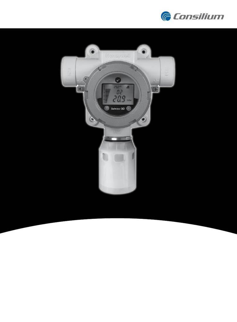
Other Consilium Gas Detector manuals

Consilium
Consilium ST350 User manual

Consilium
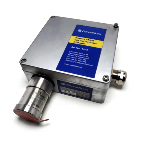
Consilium Salwico ST400 H2S Use and care manual

Consilium
Consilium Salwico GD True IR GS5000 Use and care manual

Consilium
Consilium Salwico GD User manual

Consilium
Consilium Salwico ST200 Use and care manual

Consilium
Consilium Salwico SW2020 User manual

Consilium
Consilium PG11 User manual
Popular Gas Detector manuals by other brands

Emerson
Emerson GDU-Incus quick start guide

TELEDYNE OLDHAM SIMTRONICS
TELEDYNE OLDHAM SIMTRONICS OLC user manual

BGS technic
BGS technic 2198 instruction manual

Inficon
Inficon IRwin S quick start guide

aquilar
aquilar AquiTron AT-MGS-402 Installation & operation instructions

DALEMANS
DALEMANS DAT 420 installation instructions