Remote description
2 TX_D
3 RX_D
5 GND
Audio connectors
1 GND
2 Positive
3 Negative
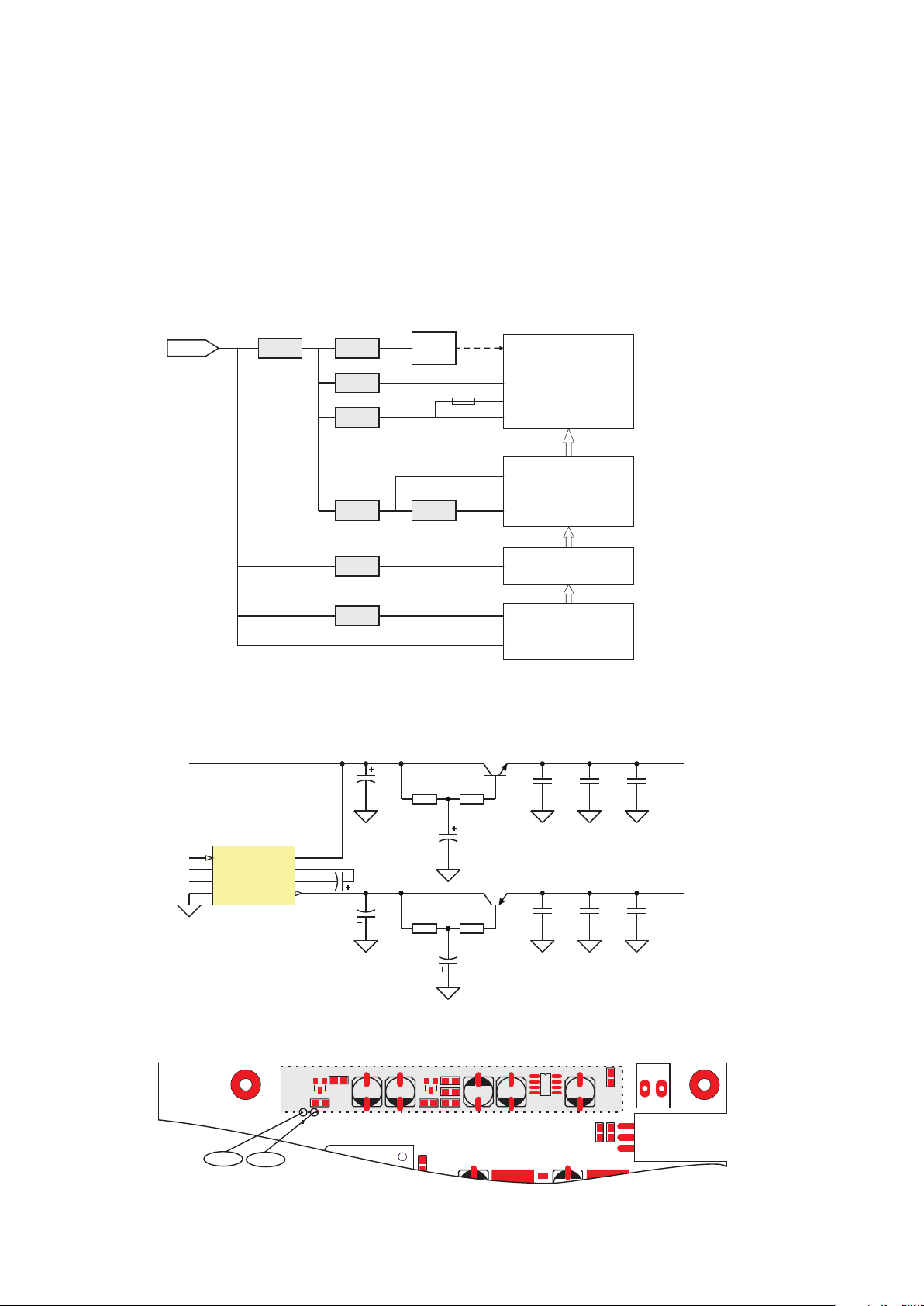
Attach audio inputs to the Left and Right XLR connectors on the rear panel. (The
Left channel audio is used on Mono.) Pin 1 of the XLR connector goes to chassis
ground. Pins 2 and 3 represent a balanced differential input. They may be connected to balanced or
unbalanced left and right program sources.
By bringing the audio return line back to the program source, the balanced
differential input of the transmitter is used to best advantage to minimize noise.
This practice is especially helpful if the program lines are fairly long, but is a good
practice for any distance.
The input impedance can be set at 600Ω or 10KΩ by the toggle switch of real panel.
Toggle switch Set
The toggle switch is use for set audio input impedance and pre-emphasis.
Audio input impedance can set at 10KΩ or 600Ω.
Pre-emphasis can be set at 25µs,50µs,75µs or OFF(flat).
25µs and 50µs can be combine to 75µs.
1
3
2
1
5
69
1 2 3 4 5 6
Right chanel input impedance
Right chanel pre-emphasis
Right chanel pre-emphasis
Left chanel pre-emphasis
Left chanel pre-emphasis
Left chanel input impedance
10KΩ
50µs
25µs
25µs
50µs
10KΩ
600Ω
OFF
OFF
OFF
OFF
600Ω
Up Down
Remote port is a RS–232C compatible serial interface. The baud is 9600 Bps.
Evey framing have 16 bytes.,
Comunication protocol:
The message structure is show below.
When the command has been active, it return ‘OK’, otherwise return ‘ERROR’.
Byte
1
2-6
7
9
10-11
12-14
15-16
8
Description
Head
Frequency
Encode mode
Audio source
Length
087510
1 byte
5 byte
1 byte
1 byte
1 byte
2 byte
3 byte
2 byte
0
0
0
00
080
<CR>
Pre-emphasis
Audio attenuate
RF power
$
Example
0DH 0AH
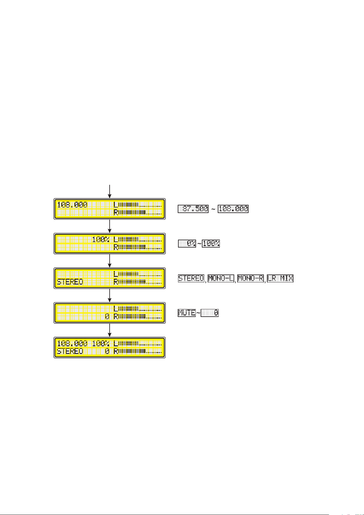
000 ~ 100 (0 ~ 100%)
00~16
2: 75µs
1: 50µs
0: OFF(Flat)
1: Digtal input
0: Analog input
3: LR-MIX
2: MONO-R
1: MONO-L
0: STEREO
Unit: KHz
Fixed
Comment
End
*
*
*No effects in this version