MD150E –pulses and velocity counter (02.06.2014)
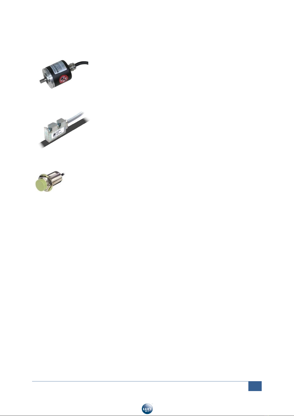
Encoders
Incremental encoders are designed for angle displacement measurement,
which means measurement of angle, number of rotation and angle
velocity. Using belt drive, cog wheel or friction wheel it is possible to
measure linear displacement.
Encoder allow to define position by counting pulses. It can also recognize
direction of movement due to phase shift of A and B channel (square wave signal).
Some encoders have C zero channel, which by each rotation indicates an absolute position. It can be
used for designation of zero position.
Linear magnetic encoders
Linear encoders are designed for direct measurement of linear
displacement. Incremental length measuring system consisting of read
head and magnetic tape. An example of sensor is GC-MK2 or GC-MK5
from WObit’s offer.
Proximity sensors, Area sensors
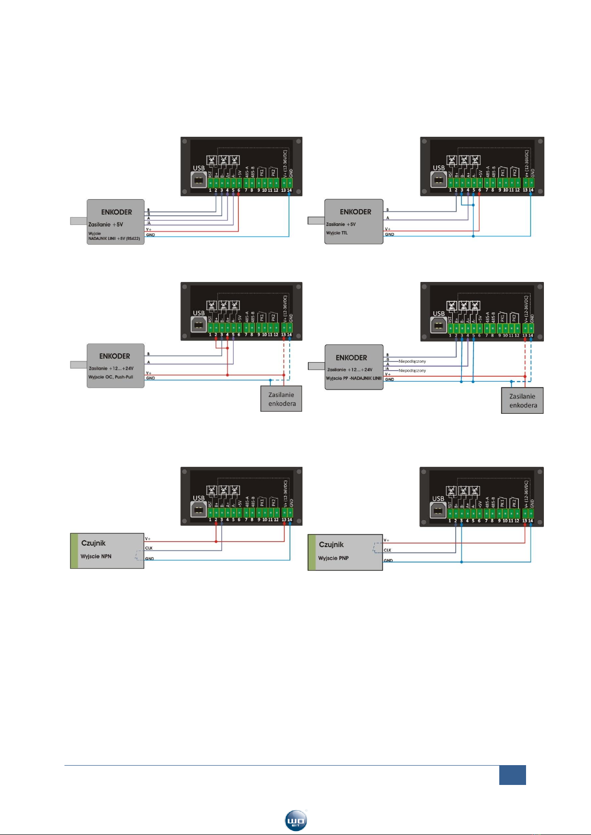
All sensors with output signal NPN or PNP can be connected directly to MD150E
counter to count number of this signals. For example this sensors can be used for
counting numbers of elements on a production line or for defining numbers of
rotation/ velocity of measuring wheel.
CLOCK/DIRECTION signals for controlling servomotors and stepper motor drivers
For controlling servomotors and stepper motor drivers often are used CLOCK/DIR signals. This signal
can be connected directly to MD150E counter, then it can be used for direct indication of motor
position/velocity.
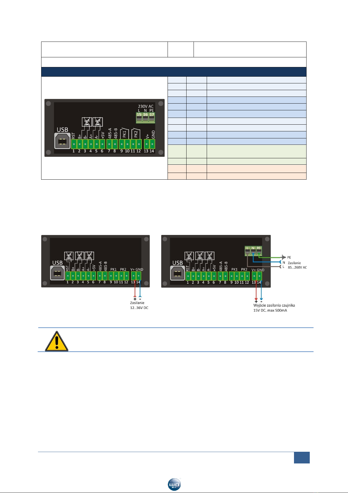
2.5 Input signals –way of connection
MD150E counts pulses from two opt insulated A and B input channels + zeroing signal (RST). This
signals can be given asymmetrically (input + or –connected to sensor’s ground) as well as
symmetrically (straight signal and negation + and - inputs simultaneously). Most of rotary and linear
encoders give asymmetrical signal (differential) due to greater transmission resistance for industrial
noise. Simple proximity sensors usually give straight signal (without negation).
Level of transducers input signal depend on electronic standard. The most popular is O.C. (voltage
supply +24 V, +12 or +5 V). This standard can’t be used for long distances with high signal frequency.
At distances up to 100 m and high rotational velocity of transducer usually is used Line Driver
standard (RS422). At this standard at transducer are available also A and B signal negations. Then
should be used proper cable with correct impedance (signal send in pairs, e.g. A+/A-).
MD150E has fully opt insulated differential counter inputs, on which can be given signals in range
5..24V (between „+” and „-”clamp). It can be integrated directly with most of sensors (supplied
from +5V as well as +24V).
Owing to input signal on opt-isolator is internally formed in square course with proper slope (for
correct pulse identification). As pulse generator can be used almost any element with slow increasing
pulse like optical sensor or proximity sensor. In case of electromechanical pulse sources, the