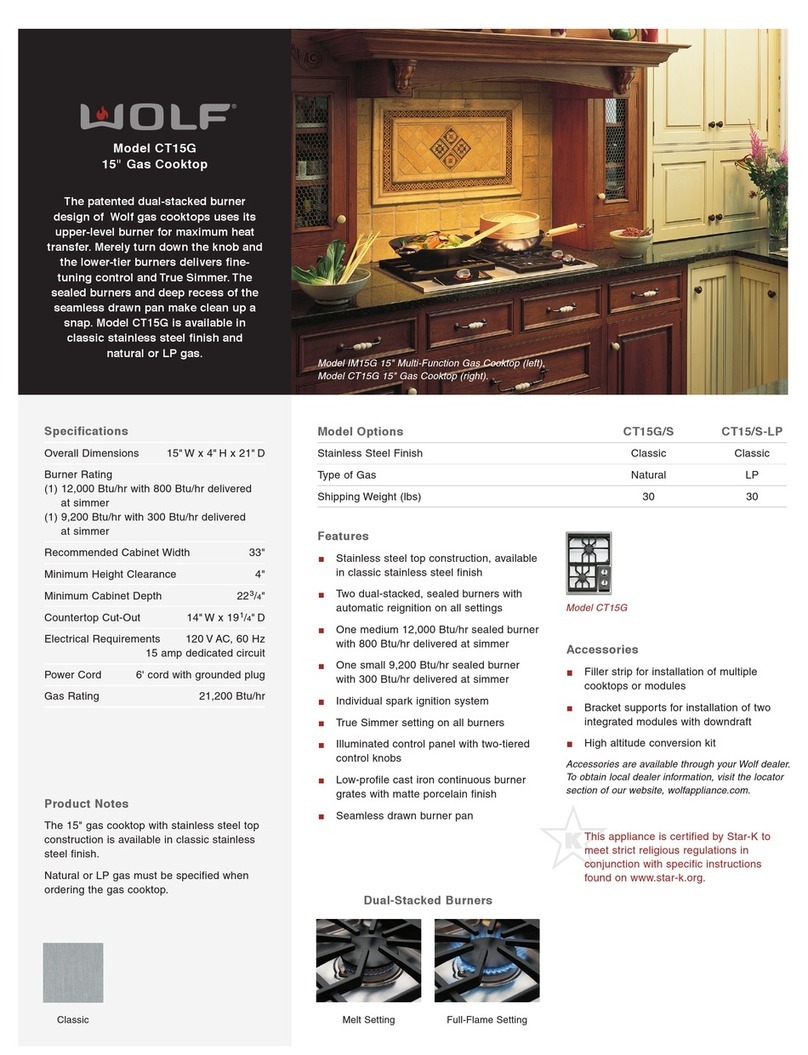
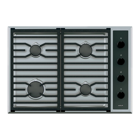
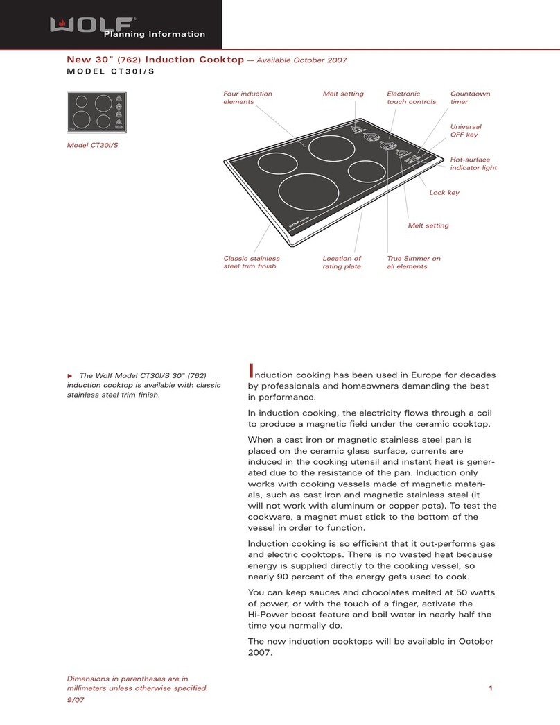
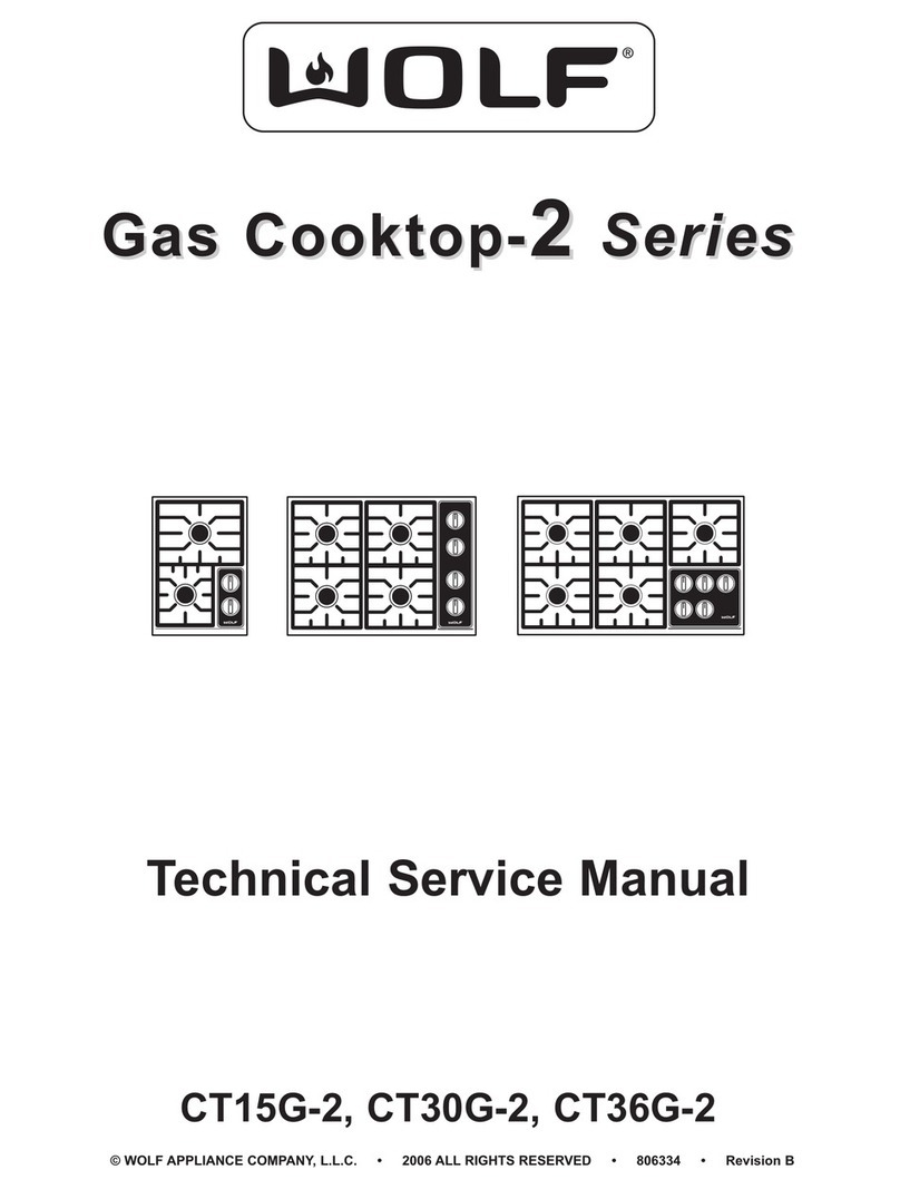
Wolf CE152TF/S Operating manual

Page 2
Integrated Modules
Integrated Modules
General Information
1-2
#826498 - Revision B - December, 2016
INTRODUCTION
This Technical Service Manual has been compiled to provide the most recent technical service information. This
information enables the service technician to troubleshoot and diagnose malfunctions, perform necessary repairs
and return the appliance to proper operational condition.
The service technician should read the complete instructions contained in this service manual before initiating any
repairs on a Wolf Appliance.
For installation information see Induction and Electric Cooktops Installation Guide, Gas Cooktops Installation
Guide, Multifunction Cooktop Installation Guide, Steamer Installation Guide, Fryer Installation Guide, and
Grill Installation Guide available at http://www.subzero-wolf.com/trade-resources/product-specifications.
For Use and Care information see Induction and Electric Cooktops Use and Care Guide, Gas Cooktops Use
and Care Guide, Multifunction Cooktop Use and Care Guide, Steamer Use and Care Guide, Fryer Use and
Care Guide, and Grill Use and Care Guide available at http://www.subzero-wolf.com/trade-resources/product-
specifications.
IMPORTANT SAFETY INFORMATION
Below are the Product Safety Labels used in this manu-
al. The "Signal Words" used are WARNING and
CAUTION.
Please note that these safety labels are placed in areas
where awareness of personal safety and product safety
should be taken and lists the precautions to be taken
when the signal word is observed.
This manual is designed to be used by Certified Service Personnel only. Wolf Appliance, Inc. assumes no
responsibility for any repairs made to Wolf appliances by anyone other than Certified Service Technicians.
INDICATES THAT HAZARDOUS OR UNSAFE
PRACTICES COULD RESULT IN SEVERE PERSON-
AL INJURY OR DEATH.
Indicates that hazardous or unsafe practices could
result in minor personal injury or product and/or
property damage
In addition, please pay attention to the signal word
“NOTE”, which highlights especially important informa-
tion within each section.
The information and images are the copyright property of Wolf Appliance, Inc., an affiliate of
Sub-Zero Group, Inc. Neither this manual nor any information or images contained herein may be copied or used in
whole or in part without the express written permission of Wolf Appliance, Inc., an affiliate of Sub-Zero Group, Inc. ©
Wolf Appliance, Inc., all rights reserved.
TECHNICAL ASSISTANCE
If you should have any questions regarding the appli-
ance and/or this manual, please contact:
Wolf Appliance, Inc.
ATTN: Service Department
P.O. Box 44988
Madison, WI 53744 - 4988
Customer Care
Phone #: (800) 332 - 9513
Facsimile #: (608) 441 - 5887
Technical Assistance
(For Technicians in Customer’s Homes Only)
Phone #: (800) 919 - 8324
Warranty Claims
Phone #: (800) 404 - 7820
Facsimile #: (608) 441 - 5886
Service Department e-mail Address:
Main Office Hours:
8:00 AM to 5:00 PM Central Time
Monday through Friday
(24/7 Phone Coverage)
Page 3
General Information
Integrated Modules
Integrated Modules
1-3 #826498 - Revision B - December, 2016
WARRANTY INFORMATION
This page contains a summary of the 2 & 5 Year Warranty that is supplied with every Wolf product, followed by a
Non-Residential Warranty Summary and then notes about the warranties.
2 & 5 Year Warranty Summary:
2 Year Total Product Warranty, parts and labor.•
3-5 Year Limited Parts Only Warranty.•
Details:
Warranty applies to products installed in United States or Canada, for residential use only.•
Warranty begins at time of unit’s initial installation.•
Warranty does not cover Wolf Appliances installed in a demonstration kitchen, test kitchen, culinary school•
kitchen, or similar installations. (See Special Warranty below)
Warranty and service information collected by Wolf Appliance, Inc. is arranged and stored under unit serial num-•
ber and/or customer’s name. Wolf Appliance, Inc requests that you have model and serial number available
whenever contacting factory or parts distributor.
3-5 Year Limited Parts Only Warranty applies to the control board, power board, display board, elements (induc-•
tion and electric), and gas burners (except appearance).
Special Warranty Summary
2 Year Total Product Warranty, parts and labor.
Details:
This Warranty applies to products installed in United States or Canada, for use in a demonstration kitchen, test•
kitchen, culinary school kitchen, and similar installations that help promote Wolf Appliance brand and its prod-
ucts.
Warranty begins at time of unit’s initial installation.•
Warranty and Service information collected by Wolf Appliance, Inc. is arranged and stored under unit serial num-•
ber and/or customer’s name. Wolf Appliance, Inc. requests that you have model and serial number available
whenever contacting factory or parts distributor.
NOTE: “ICB” appliances carry no factory warranty. The product distributor or appliance dealer may offer their own
warranty.

Page 4
Integrated Modules
Integrated Modules
General Information
1-4
#826498 - Revision B - December, 2016
RATING PLATES
CE152TF/S
2.9
3.4
824468
ELECTRIC COOKTOP
CE152T/S 176XXXXX
Wolf Appliance, Inc.
Fitchburg, WI
FOR HOUSEHOLD USE ONLY MODEL#: SERIAL#:
VOLTS : 208 ~
Hz : 50/60
240 ~
2 WIRE
kW :
“Do Not Immerse In Water” “Ne pas plonger dans l’eau”
Figure 1-1. CE152TF/S Rating Plate
Figure 1-2. CE152TF/S Rating Plate
Beneath the unit.
3.2
3.7
824473
INDUCTION COOKTOP
CI152T/S 176XXXXX
Wolf Appliance, Inc.
Fitchburg, WI
FOR HOUSEHOLD USE ONLY MODEL#: SERIAL#:
VOLTS : 208 ~
Hz : 50/60
240 ~
2 WIRE
kW :
“Do Not Immerse In Water” “Ne pas plonger dans l’eau”
Figure 1-3. CI152TF/S Rating Plate
Rating Label
Figure 1-4. CI152TF/S Rating Plate
Beneath the unit
NOTE: VAC = Volts AC; Hz = Hertz; kW = kilowatts; Nat. = Natural Gas
Rating Label
CI152TF/S

Page 5
General Information
Integrated Modules
Integrated Modules
1-5 #826498 - Revision B - December, 2016
CG152TF/S
MM15TF/S
CG152T/S
9004378
NAT. 5” WC
120 V AC 160
12000
9200
ANSI Z21.lb-2012 “HOUSEHOLD GAS COOKING APPLIANCES”
“CANI-I.I-M81/CGA IR58-1995”
1XXXXXXX
MM15T/S
9003628
NAT. 5” WC
120 V AC 160
22000
ANSI Z21.lb-2012 “HOUSEHOLD GAS COOKING APPLIANCES”
“CANI-I.I-M81/CGA IR58-1995”
1XXXXXXX
Rating Label
Rating Label
Figure 1-5. CG152TF/S Rating Plate
Figure 1-7. MM15TF/S Rating Plate
Figure 1-6. CG152TF/S Rating Plate
Beneath the unit
Figure 1-8. MM15TF/S Rating Plate
Beneath the unit

Page 6
Integrated Modules
Integrated Modules
General Information
1-6
#826498 - Revision B - December, 2016
SM152TF/S
FM15TF/S
11.3
240~
AMP
VOLTS
Wolf Appliance, Inc.
Fitchburg, WI
“DO NOT IMMERSE IN WATER” “NE PAS PLONGER DANS L’EAU”
MODEL
SERIAL
NO.
MINIMUM HORIZONTAL CLEARANCE BETWEEN THE
APPLIANCE AND COMBUSTIBLE CONSTRUCTION
EXTENDING FROM THE COOKING SURFACE TO 18"
ABOVE THE LEVEL OF THE COOKING SURFACE IS 6"
FROM SIDE WALLS, MAXIMUM DEPTH FOR OVERHEAD
CABINETS IS 13". MINIMUM VERTICAL DISTANCE
BETWEEN THE COOKING SURFACE AND COMBUSTIBLE
MATERIALS ABOVE THE APPLIANCE IS 30". MINIMUM
HORIZONTAL DISTANCE BETWEEN OVERHEAD
CABINETS INSTALLED TO EITHER SIDE OF THE APPLIANCE
SHALL NOT BE LESS THAN THE NOMINAL WIDTH OF THE
APPLIANCE. MINIMUM HORIZONTAL DISTANCE FROM SIDE
AND BACK OF APPLIANCE TO ADJACENT VERTICAL
COMBUSTIBLE WALLS EXTENDING ABOVE THE TOP PANEL,
6 INCHES FROM SIDE WALLS, 1 3/4 INCHES FROM REAR WALL.
MINIMUM HORIZONTAL DISTANCE FROM FRONT EDGE OF
COUNTER TO FRONT SIDE OF APPLIANCE, 1 1/2 INCHES.
FOR HOUSEHOLD USE ONLY
VOLTS
AMP
HERTZ
ELECTRICAL RATING
208~
9.7
50/60
SM15T/S
9008605
1XXXXXXX
11.3
240~
AMP
VOLTS
Wolf Appliance, Inc.
Fitchburg, WI
“DO NOT IMMERSE IN WATER” “NE PAS PLONGER DANS L’EAU”
MODEL
SERIAL
NO.
MINIMUM HORIZONTAL CLEARANCE BETWEEN THE
APPLIANCE AND COMBUSTIBLE CONSTRUCTION
EXTENDING FROM THE COOKING SURFACE TO 18"
ABOVE THE LEVEL OF THE COOKING SURFACE IS 6"
FROM SIDE WALLS, MAXIMUM DEPTH FOR OVERHEAD
CABINETS IS 13". MINIMUM VERTICAL DISTANCE
BETWEEN THE COOKING SURFACE AND COMBUSTIBLE
MATERIALS ABOVE THE APPLIANCE IS 30". MINIMUM
HORIZONTAL DISTANCE BETWEEN OVERHEAD
CABINETS INSTALLED TO EITHER SIDE OF THE APPLIANCE
SHALL NOT BE LESS THAN THE NOMINAL WIDTH OF THE
APPLIANCE. MINIMUM HORIZONTAL DISTANCE FROM SIDE
AND BACK OF APPLIANCE TO ADJACENT VERTICAL
COMBUSTIBLE WALLS EXTENDING ABOVE THE TOP PANEL,
6 INCHES FROM SIDE WALLS, 1 3/4 INCHES FROM REAR WALL.
MINIMUM HORIZONTAL DISTANCE FROM FRONT EDGE OF
COUNTER TO FRONT SIDE OF APPLIANCE, 1 1/2 INCHES.
FOR HOUSEHOLD USE ONLY
VOLTS
AMP
HERTZ
ELECTRICAL RATING
208~
9.7
50/60
FM15T/S
9008606
1XXXXXXX
Rating Label
Rating Label
Figure 1-9. SM15TF/S Rating Plate
Figure 1-11. FM15TF/S Rating Plate
Figure 1-10. SM15TF/S Rating Plate
Beneath the unit
Figure 1-12. FM15TF/S Rating Plate
Beneath the unit

Page 7
General Information
Integrated Modules
Integrated Modules
1-7 #826498 - Revision B - December, 2016
GM15TF/S
11.7
240~
AMP
VOLTS
Wolf Appliance, Inc.
Fitchburg, WI
“DO NOT IMMERSE IN WATER” “NE PAS PLONGER DANS L’EAU”
MODEL
SERIAL
NO.
MINIMUM HORIZONTAL CLEARANCE BETWEEN THE
APPLIANCE AND COMBUSTIBLE CONSTRUCTION
EXTENDING FROM THE COOKING SURFACE TO 18"
ABOVE THE LEVEL OF THE COOKING SURFACE IS 6"
FROM SIDE WALLS, MAXIMUM DEPTH FOR OVERHEAD
CABINETS IS 13". MINIMUM VERTICAL DISTANCE
BETWEEN THE COOKING SURFACE AND COMBUSTIBLE
MATERIALS ABOVE THE APPLIANCE IS 30". MINIMUM
HORIZONTAL DISTANCE BETWEEN OVERHEAD
CABINETS INSTALLED TO EITHER SIDE OF THE APPLIANCE
SHALL NOT BE LESS THAN THE NOMINAL WIDTH OF THE
APPLIANCE. MINIMUM HORIZONTAL DISTANCE FROM SIDE
AND BACK OF APPLIANCE TO ADJACENT VERTICAL
COMBUSTIBLE WALLS EXTENDING ABOVE THE TOP PANEL,
6 INCHES FROM SIDE WALLS, 1 3/4 INCHES FROM REAR WALL.
MINIMUM HORIZONTAL DISTANCE FROM FRONT EDGE OF
COUNTER TO FRONT SIDE OF APPLIANCE, 1 1/2 INCHES.
FOR HOUSEHOLD USE ONLY
VOLTS
AMP
HERTZ
ELECTRICAL RATING
208~
10.1
50/60
GM15T/S
9008607
1XXXXXXX
Rating Label
Figure 1-13. GM15TF/S Rating Plate Figure 1-14. GM15TF/S Rating Plate
Beneath the unit
Conforms to ANSI/UL Std. 1026
Cert. to CAN/CSA Std. No. CSA E60335.2.6
193XXXXX
TM15T/S
AC 208 V 2.7 kW 60 Hz
AC 240 V 3.1 kW
Ser.N°.:
Made in Austria / Fabriqué au Autriche
Household Use Only
Seulement pour
applications domestiques
Manufactured: November 2016
Rating Label
Figure 1-15. TM15TF/S Rating Plate Figure 1-16. TM15TF/S Rating Plate
Beneath the unit
TM15TF/S

Page 8
Integrated Modules
Integrated Modules
General Information
1-8
#826498 - Revision B - December, 2016
Refer to this key for an example of the model numbers.
Model: ICB CE 15 2 T F / S
International Designation
Product Configuration
Size
Number of Element Assemblies
Unit Style
Pairing Frame
Edge Style
Product Configuration
CE = Cooktop Electric
CI = Cooktop Induction
CG = Cooktop Gas
MM = Multifunction Module
SM = Steamer Module
FM = Fryer Module
GM = Grill Module
TM = Teppanyaki Module
Size
15 = 15 - inch wide unit
Number of Element Assemblies
2 = Two element assembly unit
Unit Style
T=Transitional
Pairing Frame
F = Pairing Frame: Unit framed designed to match cook-
tops with “F” in the model number. Integrated Module
frame did not change, only the model number.
Edge Style
S = Stainless Steel Frame
NOTE: On the CE152TF/S/208 the “/208” denotes a
unit designed for 208 VAC.
•
COOKTOP FEATURES
CE152TF/S
High-frequency pulsation technology creates superior•
cooktop performance and control, at both the high end
and low end.
True Simmer setting provides the consistent low heat•
you need for extended, even all-day simmering of
soups and sauces, and for confident preparation of
more delicate dishes.
Melt settings allow you to melt even fine chocolate•
and other delicate foods without scorching.
Sliding touch controls with white LED lighting are easy•
to read and easy to use.
Hot surface indicator illuminate as a convenient safety•
reminder and can remain on, even after the cooktop
controls are turned off.
Black ceramic glass is resistant to scratching, staining,•
impact and heat.
Independent timer up to 99 minutes.•
CI152TF/S
Induction elements heat cookware, not the glass, for a•
cooler, safer cooking surface.
Cookware sensing - elements will not be energized•
without an induction compatible pan on the surface.
Boost mode boosts power by diverting power from an•
adjacent element.
Hot surface indicator illuminate as a convenient safety•
reminder and can remain on, even after the cooktop
controls are turned off.
Black ceramic glass is resistant to scratching, staining,•
impact and heat.
Independent timer up to 99 minutes.•
CG152TF/S
Dual-stacked, sealed burners for precise control and•
easy cleanup.
Flame recognition and automatic reignition for safety•
and ease of use.
True simmer setting on all burners prevents scorching.•
Push-to-activate backlit controls are invisible when the•
cooktop is off.
COOKTOP FEATURES
MODEL NUMBER KEY

Page 9
General Information
Integrated Modules
Integrated Modules
1-9 #826498 - Revision B - December, 2016
•
COOKTOP FEATURES
MM15TF/S
High-output 22,000 BTU/hr burner sculpts its flame for•
perfect stir frying.
Innovative “two in one” grate for standard or wok cook-•
ing.
Flame recognition and automatic reignition for safety•
and ease of use.
Push-to-activate backlit controls are invisible when the•
cooktop is off.
SM15TF/S
Powerful 2700 watt heating element quickly steams•
meats, grains and more.
Functions as a slow cooker for 8-10 hours.•
Increased precision with 10 preset power levels and•
the ability to adjust in 1° increments.
Does everything from proofing bread to melting fine•
chocolate.
Holds 20 cups of liquid.•
Stackable stainless steel pans.•
Advanced lid seal holds in steam for consistent tem-•
perature.
Electronic drain releases full capacity of water in just 2•
minutes.
FM15TF/S
Crisper, lighter fried food without unnecessary grease.•
Melt feature for shortening or lard.•
Three wire baskets, dishwasher safe.•
Illuminated touch controls and convenient lock feature.•
Manual locking drain.•
GM15TF/S
Two independent heating modules for grilling multiple•
items.
Added flavor and even heating with ceramic bri-•
quettes.
Low-profile grilling grates for seamless design.•
Illuminated touch controls and convenient lock feature.•
TM15TF/S
Integrated design, slim 15” width pairs well with other•
Wolf modules.
Fast preheat and temperature response.•
Flexible cooking surface - bridge between two zones•
Easy to clean stainless steel surface.•
illuminated touch controls and convenient lock feature.•
COOKTOP FEATURES

Page 10
Integrated Modules
Integrated Modules
General Information
1-10
#826498 - Revision B - December, 2016
INTEGRATED MODULE CONFIGURATIONS
Model Number: CI152TF/S
Description: Cooktop Induction, 15”, Two Coil
Assemblies, Transitional / Stainless steel
15” Two Coil Assemblies - Induction
15” One Burner Assembly - Gas
Model Number: MM15TF/S
Description: Multifunction Module, 15”, One Burner
Assembly, Transitional / Stainless steel
Model Number: CE152TF/S
Description: Cooktop Electric, 15”, Two Element
Assemblies, Transitional / Stainless steel
15” Two Element Assemblies - Electric
15” Two Burner Assemblies - Gas
Model Number: CG152TF/S
Description: Cooktop Gas, 15”, Two Burner
Assemblies, Transitional / Stainless Steel

Page 11
General Information
Integrated Modules
Integrated Modules
1-11 #826498 - Revision B - December, 2016
15” Two Heating Elements - Electric
Model Number: GM15TF/S
Description: Grill Module, 15”, Two Burner Assembly,
Transitional / Stainless steel
15” One Heting Element - Electric
Model Number: SM15TF/S
Description: Steamer Module, 15”, One Burner
Assembly, Transitional / Stainless steel
15” One Heating Element - Electric
Model Number: FM15TF/S
Description: Fryer Module, 15”, One Burner Assembly,
Transitional / Stainless steel
15” Two Coil Assembly - Induction
Model Number: TM15TF/S
Description: Teppanyaki Module, 15”, Two Coil
Assembly, Transitional / Stainless steel

Page 12
Integrated Modules
Integrated Modules
Electronics and Gas Theory
2-2
#826498 - Revision B - December, 2016
ELECTRONICS
This section describes the basic operation of the module electronics and how the touch pad responds to input com-
mands. The electronics operation of the CE152TF/S, CI152TF/S, SM15TF/S, FM15TF/S, GM15TF/S, and the
TM15TF/S are very similar. Model specific information is listed below the general operation.
Touch Pads
Global Touch Pads - All Models
LOCK - Locks or unlocks the entire unit. Touch and hold for 3 seconds. Acceptance beep when state•
changes. Padlock is displayed when locked.
ALL OFF - Disables entire unit. Red circle displayed when any heating component is in use.•
“+” - Adds time to the count down timer. Valid Selection beep to acknowledge touch.•
“-” - Decreases time to the count down timer. Valid Selection beep to acknowledge touch.•
TIMER - Activate and deactivate the timer. Valid Selection beep to acknowledge touch.•
Control Zone Pads
ON/OFF - Enables or disables individual control zone.•
SIM - sets power to level 1.•
MLT - sets power to level 1.•
LO - sets power to level 1.•
HI - sets power to level 10.•
ZONE 2 - CE152TF/S - Activates Zone 2 on hobs with two or more zones.•
BOOST - CI152TF/S - sets power to Boost and adjusts adjacent power levels as required by the induction•
power sharing scheme. Toggles Boost off if already engaged.
BRIDGE - TM15TF/S - Activates adjacent induction coil to same power level.•
DRAIN - SM15TF/s - enables or disables the electronic drain valve.•
“+” (temperature) - SM15TF/S and FM15TF/S - increases the set temperature by one degree.•
“-” (temperature) - SM15TF/S and FM15TF/S - decreases the set temperature by one degree.•
‘’ . . . .” - Sets power to levels 2 through 9.•
Annunciator - All Models
Unit must be in idle mode to adjust annunciator.•
Adjust annunciator volume and frequency in user options mode. See Frequency Duration and Selection•
Chart on the next page.
Factory default setting for volume is medium.•
Factory default setting for frequency is medium.•
Low frequency is 1.5 kHz. Medium frequency is 2.0 kHz. High Frequency is 2.5 kHz.•

Page 13
Electronics and Gas Theory
Integrated Modules
Integrated Modules
2-3 #826498 - Revision B - December, 2016
HOT Surface Display - CE152TF/S
LED is time activated between 7 seconds and 370 seconds depending on what power level is selected.•
LED turns off after allotted time based on what power level is selected.•
LED will stay on a maximum of 60 minutes after all element assemblies are off.•
HOT Surface Display - CI152TF/S and TM15TF/S
LED is on when the unit glass temperature at any coil assembly (NTC reading) is greater than 149° F.•
LED turns off when the glass temperature is below 122° F.•
Independent of any control zone activation or the unit being in lock or showroom mode.•
HOT Surface Display - SM15TF/S and FM15TF/S
LED is on when the RTD, Steamer Fill Sensor is greater than 140° F.•
LED turns off when RTD, Steamer Fill Sensor is below 122° F.•
Independent of any control zone activation or the unit being in lock or showroom mode.•
HOT Surface Display - GM15TF/S
LED is on after the GM15TF/S has been on for more than five minutes.•
LED turns off when the GM15TF/S has been OFF for more than 30 minutes.•
Name Duration Type Occurrence
Valid Selection 280 ms Beep Touch on valid pad
Invalid Selection 750 ms Beep Touch on invalid pad
Acceptance 280 ms Beep Twice with 250 ms delay on the successful receipt of a command
Timer Complete 750 ms Beep Four times with 200 ms delay on the expiration of a timer
Then every 8500 ms until acknowledge
Failure 750 ms Beep Four times with 200 ms delay on priority 1 errors
One Minute
Remaining 750 ms Beep When there is one minute remaining on a timer or timed cook cycle.
Frequency Duration and Selection Chart - All Models
NOTE: ms = milliseconds

Page 14
Integrated Modules
Integrated Modules
Electronics and Gas Theory
2-4
#826498 - Revision B - December, 2016
Timer
General Information - All Models
Available in any mode except Lock Mode, Sabbath mode, User Option mode, and Diagnostic mode.•
The 2-digit display is blank unless there is a fault, in Diagnostic mode, or in Showroom mode.•
Shows minutes until the timer reaches 1 minute.•
Switches to seconds at 1 minute, and counts down from 60 seconds.•
Timer is paused until 3 seconds after the last change in value then countdown begins.•
Adjusting the time on a running timer resets the seconds to zero.•
If counting down seconds and the “-” pad is touched the timer stops without alarm.•
Maximum time allowed is 99 minutes.•
Minimum time allowed is 1 minute.•
Timer turns off after 10 seconds if no time is entered.•
Starting the Timer - All Models
1. Unlock the unit.
2. Press and release the TIMER pad.
3. Time increases and decreases with a touch of the “+” or “-” pad.
If the “+” or “-” pad is held continuously for 3 intervals the count rate increases.•
If the “+” or “-” pad is held continuously for additional 3 intervals, the count rate increases again.•
A continuously held “+” or “-” increases in this manner: 00, 01, 02, 03, 04, 05, 10, 15, 20, 30, 40, 50,•
60, 70, 80, 90, 99.
Ending the Timer - All Models
Touch of the TIMER or “-” pad stops Timer Complete beep and clears the display.1.
At 60 seconds the One Minute Remaining beep sounds.•
At 00 the Timer Complete beep sounds until acknowledged.•
Touch of the “+” pad adds time to the timer as described above.2.
Display States of the Timer - All Models
When active the 2-digit display and Timer are on.•
Other displays are as described in Idle Mode or Operational Mode.•
Fan
Fan - CE152TF/S
Fan control is determined by the temperature on the heat sink.•
After element assemblies are off fan continues to run until heat sink temperature is below 113° F, or up to•
600 seconds.
Fan is limited to low speed when the element assemblies are off.•
Temperature thresholds:
• 113° F – start low speed
• 131° F – start high speed

Page 15
Electronics and Gas Theory
Integrated Modules
Integrated Modules
2-5 #826498 - Revision B - December, 2016
Fan - CI152TF/S
Fan control is determined by the temperature on the heat sink.•
A very high power request, such as two elements on 100% or one on boost switches the fans on independ-•
ently of the heatsink temperature.
After generator is off, fan continues to run until heat sink temperature is below 113° F, or up to 600 seconds.•
Fan is limited to low speed when the generator is off.•
Temperature thresholds:
113° F - start low speed•
131° F - start high speed•
Fan - TM15TF/S
Fan control is determined by the temperature on the heat sink.•
A very high power request, such as both elements on 100% switches the fan on independently of the•
heatsink temperature.
After generator is off, fan continues to run until heat sink temperature is below 113° F, or up to 600 seconds.•
Fan is limited to low speed when the generator is off.•
Temperature thresholds:
113° F - start low speed•
131° F - start high speed•
Modes
Power Up Mode - All Models
All LED indicators are on for two seconds.•
Timer digits will indicate the appliance type ‘SS’ for SM15TF/S, ‘FF’ for FM15TF/S, and ‘LL’ for GM15TF/S. The•
control will default to SM15TF/S if the appliance type cannot be determined due to an EEPROM issue or if the
EEPROM is not programed.
After LED power up sequence the annunciator sounds the Acceptance beep.•
During the Acceptance beep the unit enters Lock Mode.•
LOCK display is on.•

Page 16
Integrated Modules
Integrated Modules
Electronics and Gas Theory
2-6
#826498 - Revision B - December, 2016
Lock Mode - All Models
No pad can function except for the LOCK pad or the pads associated with entering Diagnostic Mode.
Entering Lock Mode
Enter lock mode by holding LOCK pad for 3 seconds when in Idle Mode.1.
Engages after ten continuous minutes of Idle Mode.•
After power up sequence.•
Annunciator sounds Acceptance beep when Lock Mode is entered.•
LOCK LED is visible.•
Annunciator sounds Failure beep if any control zone is active when trying to enter Lock Mode.•
Exiting Lock Mode
Touch and hold the LOCK pad for 3 seconds.1.
CE152TF/S and CI152TF/S - if LOCK pad is held for more than 10 seconds unit relocks.•
SM15TF/S, FM15TF/S, GM15TF/S, and TM15TF/S - if LOCK pad is held for more than 7 seconds unit•
relocks.
Annunciator sounds Acceptance beep to indicate Lock Mode has been exited.•
LOCK LED turns off and control zones enter Idle Mode.•
Valid key presses in Lock Mode
LOCK pad for exiting Lock Mode.•
CE152TF/S, CI152TF/S, and TM15TF/S - touch and hold “+” and “-” pads for 5 seconds to enter•
Diagnostic Mode.
SM15TF/S, FM15TF/S, and GM15TF/S - touch and hold “ALL OFF” pad for 5 seconds to enter Diagnostic•
Mode.
Display states in Lock Mode
LOCK display is on.•
All other displays are off.•
Idle Mode - All Models
Unit is unlocked and control zones are inactive.
Valid key presses in Idle Mode
LOCK – Touch and hold LOCK pad to enter Lock Mode.•
ON/OFF – Touch any control zone ON/OFF pad places that control zone in Wake-Up Mode.•
TIMER – Touch TIMER pad activates the Timer.•
DRAIN - SM15TF/S - liquid temperature below 140° F, a touch and hold of the DRAIN pad for three seconds•
results in an audible chime and the drain valve will open for two minutes.
Display states in Idle Mode
All displays are off.

Page 17
Electronics and Gas Theory
Integrated Modules
Integrated Modules
2-7 #826498 - Revision B - December, 2016
Wake-Up Mode - All Models
Entering Wake-Up Mode
Touch ON/OFF pad on any inactive control zone.1.
All LEDs for that control zone flash until a power level is set.•
A valid key press must be made within 10 seconds or control zone returns to Idle Mode.•
Valid key presses in Wake-Up Mode
SIM, LO or MLT – Activates the control zone at power level 1.1.
HI – Activates the control zone at power level 10.2.
BOOST - CI152TF/S - Activates the control zone at power level Boost.3.
“…” – Activates the control zone at a power level 2 through 9.4.
ON/OFF – Touch any other control zone ON/OFF pad causes that control zone to enter Wake-Up Mode.5.
ON/OFF – Retouch of same ON/OFF pad causes control zone to return to Idle Mode.6.
ALL OFF – Causes all active control zones to return to Idle Mode.7.
CI152TF/S: Notes and Restrictions in Wake-Up Mode
If a valid key press is made but no pan is sensed on the coil assembly in 30 seconds the control zone•
returns to Idle Mode.
During the 30 second wait, the “...” LEDs for that control zone flash the power level selected.•
If a bridge is activated and a pan is detected on one control zone but not all control zones being bridged the•
“...” LEDs for the unsensed control zones flash the power level that has been selected.
If after 2 minutes one or more of the control zones in the bridge still does not sense a pot, all control zones•
in the bridge return to Idle Mode, including the sensed control zone.
Display states in Wake-Up Mode
All displays for a given control zone are flashing on/off.•
ALL OFF display is turned on.•
All other displays are off.•
Operational Mode
When any control zone is active at any power level greater than 0.
Entering Operational Mode from Wake-Up Mode - All Models
SIM/MLT/LO – Activates the control zone at power level 1.1.
HI – Activates the control zone at power level 10.2.
BOOST - CI152TF/S - Activates the control zone at power level Boost.3.
“…” – Activates the control zone at power level 2 through 9. Corresponding to the “.” which was pressed.4.
Exiting Operational Mode
ON/OFF – Touch the same ON/OFF pad returns control zone to Idle Mode.•
ALL OFF – All active control zones return to Idle Mode.•

Page 18
Integrated Modules
Integrated Modules
Electronics and Gas Theory
2-8
#826498 - Revision B - December, 2016
Valid Key Presses in Operational Mode
SIM/MLT/LO – Activates the control zone at power level 1.1.
HI – Activates the control zone at power level 10.2.
ZONE 2 - CE152TF/S - Immediately activates the Zone 2 element at the power level of Zone 1.3.
BOOST - CI152TF/S - Activates the control zone at power level Boost.4.
“…” – Activates the control zone at a power level 2 through 9.5.
ON/OFF – Retouch of same ON/OFF pad causes control zone to return to Idle Mode.6.
ALL OFF – All active control zones return to Idle Mode.7.
“+” and “-” Temperature - SM15TF/S and FM15TF/S - Three digit temperature display changes by one8.
degree with a touch of the “+” or “-” pad.
If the “+” or “-” pad is held for more than three .5 second intervals and the count is divisible by 5, the1.
display will increase or decrease at a rate of 5 counts every .5 seconds.
If the “+” or “-” pad is held for another three .5 second intervals and the count is divisible by 10, the dis-2.
play will increase or decrease at a rate of 10 counts every .5 seconds.
Example: 120, 121, 122, 123, 124, 125, 130, 135, 140, 150, 160...3.
“...” power level display will update to show the nearest power level when the temperature is adjusted4.
using the “+” or “-” pad.
BRIDGE - TM15TF/S - activates the adjacent coil at the current power level.9.
If both coils are active and BRIDGE pad is touched, the power level is set to the lower of the two active•
zones.
Display States in Operational Mode
ALL OFF is turned on.•
SIM/MLT/LO, “…”, HI, ZONE 2, BRIDGE and BOOST are on if they have been activated.•
All other displays for the active control zone are off.•
All other displays in Idle Mode are off.•
Power level indicators (SIM/MLT/LO and “…”) less than the power level selected are on.•
Power levels greater than selected power level are off.•
SM15TF/S and FM15TF/S: temperature display is on.•
Coil Assembly Operational Mode and Boost Mode Notes - CI152TF/S
If two coil assemblies are powered by the same generator board and the power demand between front and•
rear coil assembly is greater than 3700 Watts, the power level of both coil assemblies are reduced an equal
percentage to 3700 Watts combined output.
During Boost coil assemblies on the same generator board have their power level adjusted.•
If Boost is activated, a second touch of the BOOST pad deactivates Boost, returning the power level to HI.•
Boost has an operational time limit of 30 minutes.•
Boost on CI152TF/S raise 2300 Watts coil assembly to 3150 Watts. Maximum power level on 1400 Watt•
coil assembly is approximately 50%, or 700 Watts.
Temperature regulation - SM15TF/S
During preheat, the element power level will be set to 100% until the set point is reached.•
Temperature regulation - FM15TF/S
A temperature off set is applied to Main RTD that will gradually increase as the liquid temperature increases,•
so that at the maximum set-point, the maximum offset will be applied.
The maximum offset will be defined by the RTD offset configuration parameter.•

Page 19
Electronics and Gas Theory
Integrated Modules
Integrated Modules
2-9 #826498 - Revision B - December, 2016
PREHEAT - SM15TF/S and FM15TF/S
SM15TF/S
Preheat Mode engages when the Main RTD is less than 110° F.•
Preheat does not engage if Operational Mode has been active for more than 100 seconds.•
When Operational Mode is first entered the unit will engage Preheat for the first 90 seconds.•
For the first 30 seconds the unit calls for 100% power.•
For the next 60 seconds the unit calls for 0% power.•
At the end of 90 seconds:•
If RTD Steamer Fill Sensor is 18°F warmer than the Main RTD the control will enter an error mode. Power•
is cut from the element and the control displays “LO” in the temperature display.
To clear the “LO” touch the TIMER pad.•
Unit will return to Operational Mode if the RTD Steamer Fill Sensor is less than 18°F warmer than the Main RTD•
temperature.
If the Main RTD reads less than 68° F, a value of 68° F will be used.•
FM15TF/S
Preheat will only engage when the Main RTD is less than 110° F.•
Preheat will not engage if Operational Mode has been active for more than 100 seconds.•
When Operational Mode is first entered the unit will engage Preheat for the first 120 seconds.•
For the first 30 seconds the unit calls for 100% power output.•
For the next 90 seconds the unit calls for 0% power output.•
At the end of 120 seconds:•
If RTD Steamer Fill Sensor is equal to or greater than 30° F warmer than the Main RTD the control will enter•
an error mode. Power is cut from the element and the control registers a dry start error.
To clear the “LO” touch TIMER pad.•
Unit will return to Operational Mode if the RTD Steamer Fill Sensor is less than 30° F warmer than the Main•
RTD.
MELT - FM15TF/S
Melt mode will only engage when the power level is set to 1.•
Melt Mode will not engage when the Main RTD is greater than 110° F.•
Preheat (dry start detection) is not enabled during Melt.•
Boil Dry safety will be enabled at all times during Melt.•
Heating element will be set to 20% power.•
Unit will return to Operational mode when the Main RTD reaches 110° F.•
ALL OFF - All Model
De-energizes the entire unit at any time.•
Does not turn off the TIMER.•
Will not turn off the “HOT” display.•
Will not turn off Showroom mode.•
SM15TF/S and FM15TF/S - will not turn off the “Temperature” display if the Main RTD is above 140° F.•

Page 20
Integrated Modules
Integrated Modules
Electronics and Gas Theory
2-10
#826498 - Revision B - December, 2016
Error Mode - All Models
System logs initial generation of an error into memory for later inspection.•
Up to 8 errors can be logged in memory.•
All detected errors logged regardless of priority.•
Errors may be canceled by the user or be self-correcting.•
Specific zones are not recorded in diagnostic mode if a cooking zone specific error is logged.•
If there are more than 8 error codes the error log displays the most recent and discards the oldest error.•
Errors are displayed using error codes.•
Error codes are also used in Diagnostic Mode.•
When an error is displayed it is accompanied by the Failure beep.•
Active error is one that is currently being displayed, other errors can be debounced and logged while another•
error is active.
Some errors are only displayed when a pad in the affected control zone is touched.•
To clear error codes see Diagnostics mode.•
Priority Errors - SM15TF/S and FM15TF/S
Priority 1 Error:
Priority 1 errors are considered safety related or of such scope that the control is considered inoperable. These•
errors display continuously to the user, indicating that a service call is required. No user function is allowed and
any active functions are cancelled upon generation of a Priority 1 error.
The error can be cleared but will regenerate if the condition which caused the error still exists. These errors are•
displayed as a stationary ‘lock’ display and an error code in the TIMER display indicating a permanent error and
does not allow the control to be unlocked to Idle mode. The TIMER display alternates between “E” and the
error code.
Priority 2 Error:
Errors are defined as errors which could cause some possible or conditionally impaired functionality, most likely•
to be never noticed by the end user. These errors, although logged internally, are never displayed to the end
user and are generally not cancelable by the end user. These errors are only visible in Diagnostic model.
Showroom Mode - All Models
Notes and Restrictions in Showroom Mode
Full user functionality with no power being supplied to the heating assemblies.•
Available on 120 VAC (without transformer) or 240 VAC power.•
CE152TF/S and CI152TF/S: Connecting the unit to 120 VAC causes error E6. This is normal. Proceed with•
the steps to place unit in Showroom mode.
Power board fan or Generator fan may not run.•
Hot surface indicator is not visible.•
Entering Showroom Mode - CE152TF/S, CI152TF/S and TM15TF/S
To enter Diagnostic Mode touch “+” pad seven times.1.
Seven “.” displayed on left rear control zone.2.
CE152TF/S and CI152TF/S - touch the front control zone HI pad to engage showroom mode.3.
SH is displayed in the 2-digit display when in showroom mode.•
TM15TF/S - touch the rear control zone HI pad to engage showroom mode.4.
SH is displayed in the 2-digit display when in showroom mode.•
”-” pad returns to Error Code indicator and “+” pad advances to Software Version indicator.5.
This manual suits for next models
7
Table of contents
Other Wolf Cooktop manuals

Wolf
Wolf ICBCT15E User manual

Wolf
Wolf CT36I/S User manual

Wolf
Wolf CT15E/S Owner's manual

Wolf
Wolf CT36U Instructions for use

Wolf
Wolf CT15I/S Instructions for use

Wolf
Wolf REV-A 5/2010 814990 User manual

Wolf
Wolf CT30I/S User manual

Wolf
Wolf CT30G Instructions for use

Wolf
Wolf ICBMM15T/S User manual

Wolf
Wolf CT30I/S User manual
Popular Cooktop manuals by other brands

Cole Parmer
Cole Parmer 04661-43 user manual

Thermo Scientific
Thermo Scientific SUPER-NUOVA+ HP88857190 Operation manual

Belling
Belling BCT60INTP instruction manual

Venini
Venini VCG9555 user manual

Denali Plus
Denali Plus CTR1 Installation and operating instructions

AEG
AEG VITRAMIC 7250 K Instructions for use