8
05
8
AIR HEATER WD-A, WD-U
Assembly
Important:
In case of steam, pay attention that the heat exchanger is installed absolutely horizontally or in steam direction with a
slope of 1 % to condensate discharge, respectively. There must be no condensate acculumation in the heat exchanger.
An efficient ventilation has to be provided.
Pay attention to the condensate discharge manufacturer’s
assembly instructions.
Due to insufficient emptying and ventilation,
Connections towards above or below are not possible.
Do not twist connection piece!
(This will destroy the heat exchanger. No warranty).
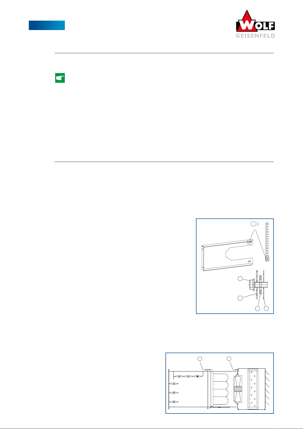
When fixing screwed flanges at the advance and return of
the heat exchanger, hold against with a suitable tool.
For later inspection work, it is purposeful to provide a slide
valve in front ot the heat exchanger.
Remove the protection caps from the connecting pipes.
Important: Connect the machine acc. to the counterflow
principle. Advance and return cf. 05.04.
Frost protection for heat exchanger:
In case of outside air operation, provide anti-frost thermostat on the air exit side of the heat exchanger!
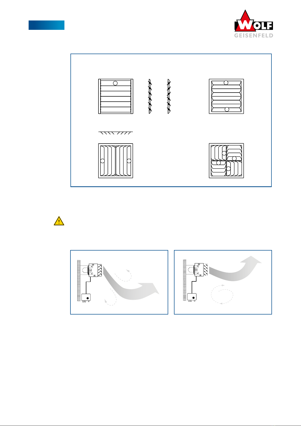
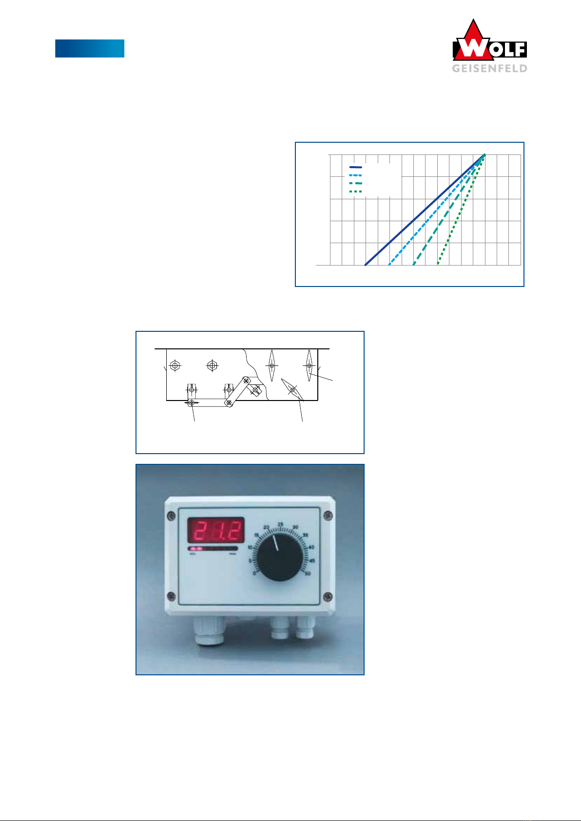
05.05 Ventilation Valve and Emptying Cock
Pay attention that the ventilation valve is installed at the highest point. Arrange the emptying cock at the lowest point,
so that a complete emptying of the heat exchanger is possible. As a precaution, blow through the heat exchanger with
compressed air in order to achieve a complete emptying (frost protection).
05.06 Motor Protection Louver
The installation of the motor protection louver is necessary in case of
higher heating media in order to protect the fan motor from overhea-
ting when it stands still. The thermo-contacts integrated in the motor
would react and stop the motor. Therefore use motor protection louver
in case of high advance temperature of the heating medium. Without
motor protection louver, WD-A-machines may be operated up to an
advance temperature of the heating medium of:
Wall Machine Ceiling Machine
without accessories
(free suction- extraction)
130 °C 120 °C
with accessories (at the suction) 120 °C 120 °C
In case of higher heating media from pump hot water 130 /100 on,
from vapour 4 bar on, the motor protection louver (order No. 595)
must be installed between heat exchanger and motor.
Attention: When using the motor protection louver, the sheet bracket
long (order No. 650) is required for wall and ceiling assembly.
Additional measures / replacement measures:
• If the operation is unregulated by the heating medium, install
motor protection louver.
• If the operation is regulated by the heating medium, provide
fan disconnection, when the regulation valve is closed.
Especially in case of an advance temperature of the heating
medium of more than 180 °C, to be provided by all means.
Apart from the motor protection function, the motor protection louver
can also be used as frost protection flap at machines with pure outside air operation.
Function: Fan off - motor protection louver (frost protection flap) closed.
300 mm