WolfPack HDTV1000TR User manual

1
HDTV1000TR
PoE IP Matrix Extender with WEB GUI Control
Version: V2020.001
User Manual

2
1. Introduction
It’s a IP video matrix is based on TCP/IP LAN technology to process and distribute HD
video signal. Better than traditional video matrix system, use distributed system
architecture and embed long distance transmission function inside, which advance largely
reduce infrastructure invest and installation cost.
Based on this advance framework, it can realize seamlessly overlying and expansion,
making sure that system is equipped with sound expansibility. It can set up accordingly to
needs for some small systems at preliminary stage to reduce the investment. For example,
a traditional matrix normally requires a system of 8TX+16RX or 16TX+16RX to configure
a 5TX+10RX small system. But an actual 5TX+10RX configuration is enough when using
this system. In the expansion of projects, we can add certain quantity of transmitter and
receiver to meet the actual needs.
The Features and flexible networking structure enable this system to meet the
requirements in meeting, education, small business and family scenario economically and
efficiently.
It provides WEB UI to control system configuration, signal switch and batch scenarios
setting, which making management more convenient for customers. It also provide CGI,
SOCKET interface for customer to integrate this system into existing management system
for central management.
2. Features
➢Resolution up to 1080P@60Hz,
➢The transmission distance up to 100m/330ft with POE
➢Or up to 200m/658ft with DC12V power supply
➢Support PoE(802.3AF), easy for installation, improve system robustness
➢Support HDMI loop-out on sender
➢Support seamless video switching, no black screen
➢Support WEB UI for system management
➢Provide CGI/SOCKET for accessing of up layer control system
➢Support software update by WEB or command line
➢Maximum up to 120 senders * 120 receivers
3. System Devices
The common IP video matrix system includes 3 devices
Receiver
Sender
Ethernet switch with IGMP&POE function
Receiver
Front Panel
3
ID
Typ
e
Descripti
on
Out
Output
HDMI video output
POWER DC 12V
Input
12V DC Power input
(Output 12V DC when POE working)
Reset
Button
Long press to reset device
POWER
Indication Light
Light on when power on
INPUT
Indication Light
Light on when receive video data from sender
Light off when no video data received
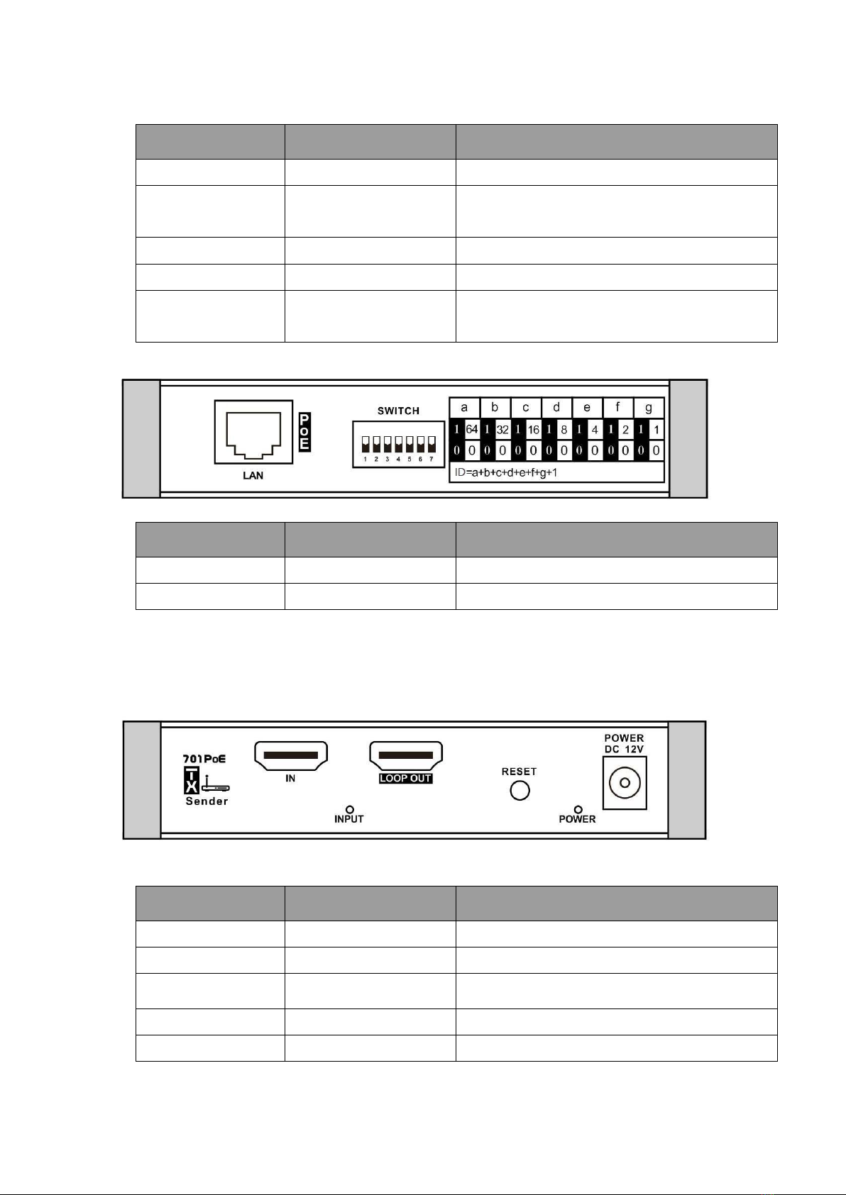
Back Panel
ID
Typ
e
Descripti
on
LAN
Input / Output
FE LAN port
SWITCH
Input dip switch
IP Address setting
Sender
Front Panel
ID
Typ
e
Descripti
on
IN
Input
HDMI video input
LOOP OUT
Output
HDMI video output
POWER DC 12V
Input
12V DC Power input(Output 12V DC when
POE )
Reset
Button
Long press to reset device
POWER
Indication Light
Light on when power on

4
INPUT
Indication Light
Light on when HDMI input valid
Light off when HDMI input none or invalid
Back Panel
ID
Typ
e
Descripti
on
LAN
Input / Output
FE LAN port
SWITCH
Input dip switch
IP Address setting
IGMP Ethernet Switch
Recommend using the IGMP featured ethernet switch as back-haul network to
support large size matrix video distribution. The actually networking setting and
configuration is based on the system capacity and QoS requirements.
The sender and receiver support PoE function and also the IGMP Ethernet switch.
4. Operation diagram
4.1 Connection diagram
4.2 Device Configuration
5
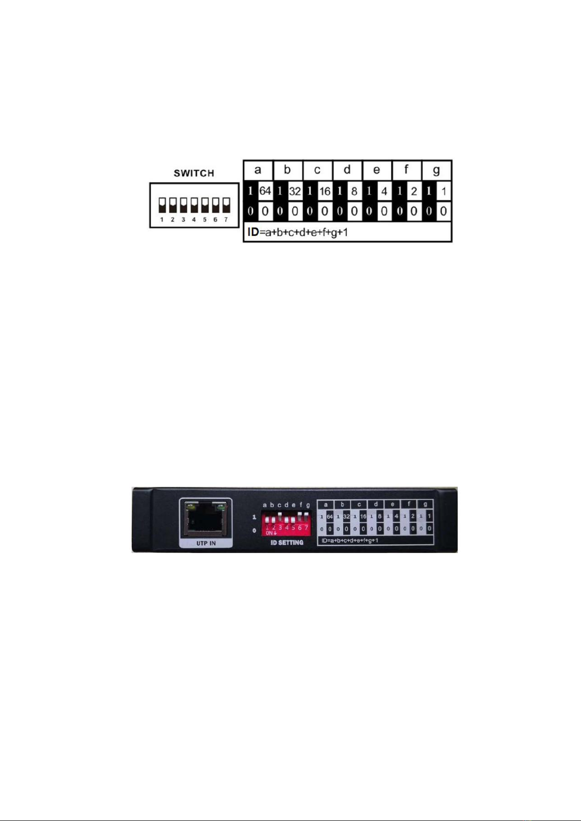
Sender Configuration
Sender should be set IP address by DIP before working. The default IP address is
192.168.1.XXX. XXX is the DIP setting value ID + 200.
DIP setting value ID defined as figure below:
From left to right, value of the first dip switch is 64 at the upper position, 0 at the bottom
position.
The value of the second dip switch is 32 at the upper, 0 at the bottom. The rest are done
by the same mechanism. ID can be obtained by adding up each value. IP address =
ID+200.
In current system configuration, the valid IP address of sender is between
192.168.1.201 - 192.168.1.224, which means the DIP switch ID should between 1 –24.
Different devices should have different IP address same address will cause IP address
confliction and system working abnormal.
*Notice: Customer need video sources exceed 24 will use another set of software,
which is not described in the scope of this document.
The picture below shows an example, device ID=16+2+1+1=20, sender IP address is
192.168.1.220:
The Main Control Unit Configuration
The main control unit and web server are working on the sender which IP address is
192.168.1.201.
So there should be one sender MUST set with IP address 192.168.1.201
If the main control unit sender hardware breaking down, user can set other sender
device to IP address 192.168.1.201 to work as new main control unit.
The picture below shows an example, sender device ID is 1, IP address is
192.168.1.201:
6
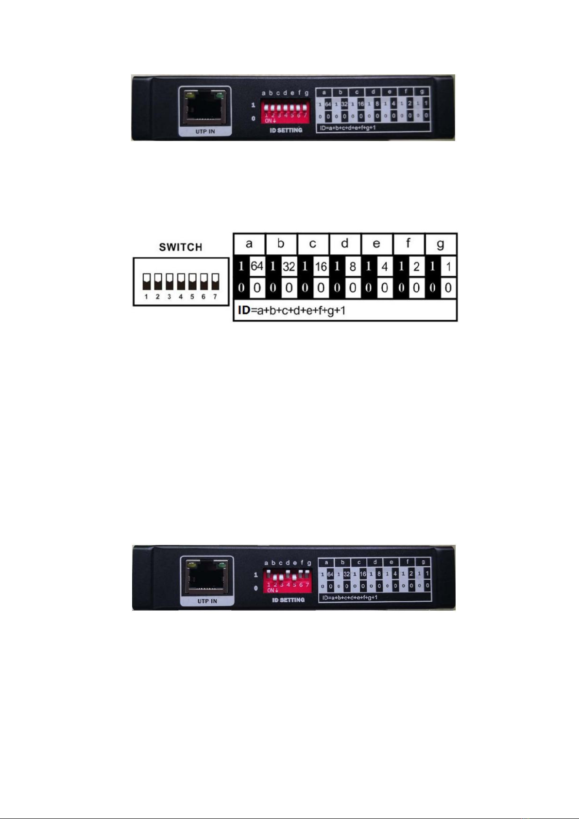
Receiver Configuration
Receiver should be set IP address by DIP before working. The default IP address is
192.168.1.XXX. XXX is the DIP setting value ID.
DIP setting value ID defined as figure below:
From left to right, value of the first dip switch is 64at the upper position, 0 at the
bottom position.
The value of the second dip switch is 32 at the upper, 0 at the bottom. The rest are
done by the same mechanism. Relavant IP address can be obtained by adding up
each value.
In current system configuration, the valid IP address of receiver is between
192.168.1.1 - 192.168.1.96, which means the DIP switch should between 1 –96.
Different devices should have different IP address, same address will cause IP
address confliction and system working abnormal.
*Notice: Customer need video displays exceed 96 will use another set of software,
which is not described in the scope of this document.
The picture below shows an example, device ID=64+8+2+1+1=76, receiver IP
address is 192.168.1.76:
IGMP Ethernet Switch Configuration
The Ethernet switches we provided are configured before delivery. User can use it
without any software configuration.
5. Device Management
User can access WEB to manage sender or receiver and get information.This system
also supports CGI /TCP /UDP for network control.
7
WEB GUI Management
Users can use universal web browser IE, Firefox, Chrome, Safari etc. to visit
device management web page. The web browser can run in PC, Pad, Phone
with Windows, MacOS, Linux, ios, Android operating systems.
* Notice: For different OS, device or web browser, the web page appearance
could be slightly different.
The URL of device management web page is
http://device_IP_address/System.html format. Say if the device IP address is
192.168.1.218, then the URL is http://192.168.1.218/System.html.
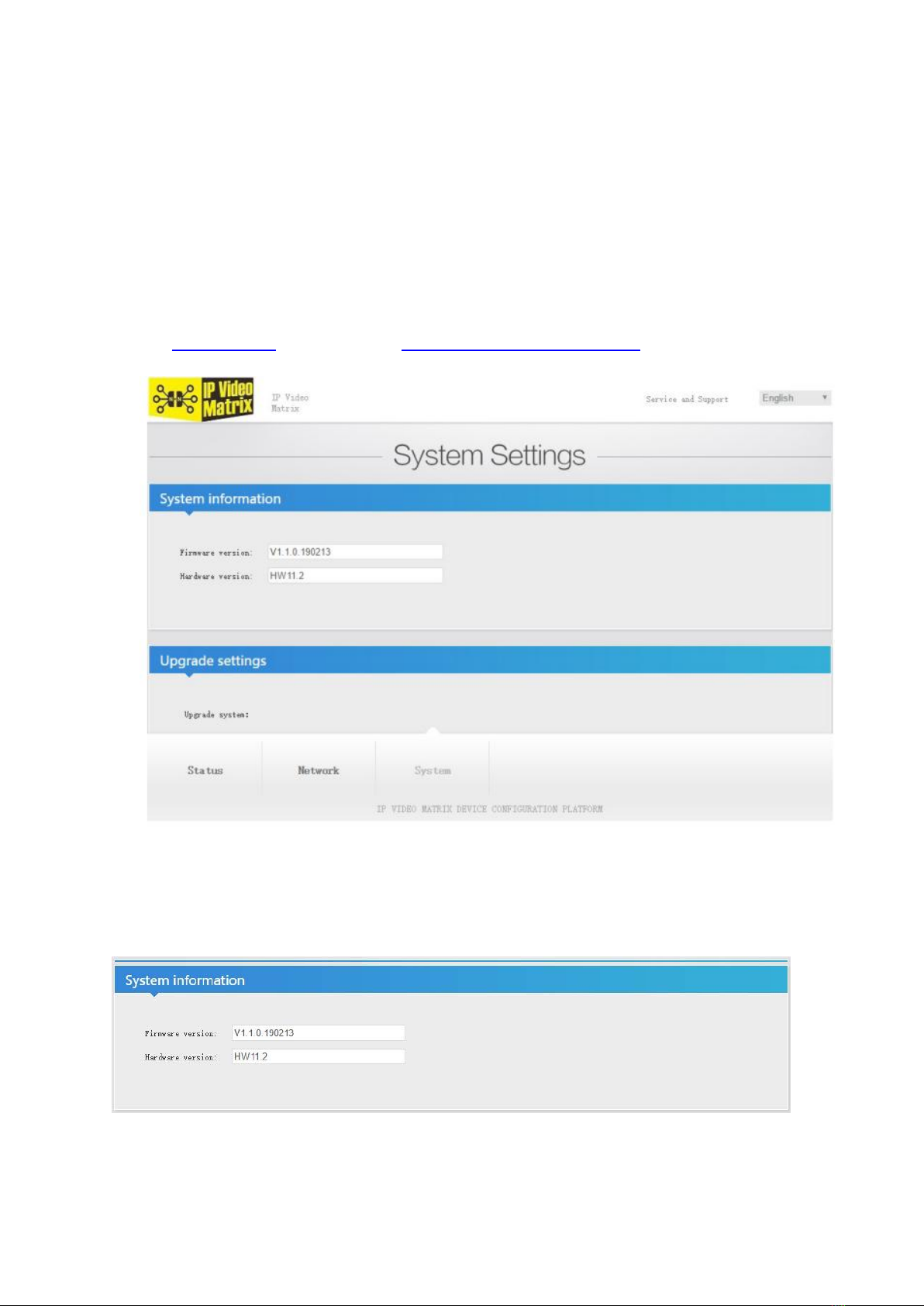
The WEB page shows as below:
Bottom menu can switch System/Network/Status page.
System Settings
System information
System information shows software and hardware version:
Upgrade Settings
User click file browse button to choose local file and click Upload button to upgrade

8
software, etc.
System Settings
Click Reboot button to reboot device.
Click Reset button, device will remove current settings and reset system default
settings.
Network Settings
Network settings page shows Ethernet network setting of current device.
Status Display
Sender device status display page shows current video input format and
audio format information. Receiver device has no status display
information

9
6 . Matrix WEB GUI Control Switch
After type the configuration and wire connection, now users are ready to do login on the
browser and start the switching, the matrix switch control WEB GUI is showing as below:
Receiver devices panel on left, configure receiver’s device name, video source device.
The display device button aligned in the sequence of IP address.
Scenario mode switch &Video source selection panel on right. Scenario mode switch
record all device connection map and recall to execute batch switching. This panel
shows video source selection in video switch function processing.
Device name configuration panel on bottom.

10
Video Switch
Click display device control button on left panel
Video source listed on right panel
Select the video source to switch
Scenario Mode Switch
Click Mode button on right panel
Pop menu selection:“APPLY” “SAVE MODE” “CANCEL”
APPLY: execute switching based on the stored connect map in this mode.
SAVE MODE: store current running devices connection map in this mode and remove
previous record.
CANCEL: back to main menu.
Table of contents
Other WolfPack Extender manuals

WolfPack
WolfPack HE23U User manual

WolfPack
WolfPack HDTVHDVE100 User manual

WolfPack
WolfPack HDTVVRP0101 User manual

WolfPack
WolfPack HDTVHYRJ2022-A20 User manual

WolfPack
WolfPack HDTVIPA100 Series User manual

WolfPack
WolfPack HDTVIPA1200 User manual

WolfPack
WolfPack HDTVHDES02-5 User manual

WolfPack
WolfPack TPUH4120 User manual

WolfPack
WolfPack TPHD-BYE User manual

WolfPack
WolfPack HDTVFME0102H10 User manual


