WOLLIS ATS User manual

Buoyancy Compensator
User’s Guide
ForModel:
ATS
HD 100
Solo
Elite 2
Switchback
HTS 2
S25
S38
X37
X55
BAC 65
BAC 85
BAC D85
1

COPYRIGHT NOTICE
This owner’s guide is copyrighted, all rights are reserved. It may not, in whole or in part,
be copied, photocopied, reproduced, translated, or reduced to any electronic medium or
machine readable for without prior consent in writing from Hollis.
Buoyancy Compensator Users’ Guide, Doc. No. 12-4012 Rev. 3 7/16/09
©Hollis
2002 Davis Street
San Leandro, Ca. USA 94577
TRADEMARK NOTICE
Hollis and the Hollis logo are registered trademarks of Hollis. All rights are reserved.
PATENT NOTICE
U.S. Patents have been issued, or applied for, to protect the following design features:
backpack systems (U.S. Patent No. 5,378,084, Gas Impermeable Laminate (U.S. Patent
No. 5,693,412), Harness Buckle (U.S. Patent No. D409,114), Weight Drop System (U.S.
Patent No. 5,218,745), Soft Backpack (U.S. Patent No. 4,952,095), and Compensating
Waistband (U.S. Patent No. 4,732,305. Also other Patents Pending.
LIMITED WARRANTY
For details, refer to the Product Warranty section on the Hollis web site:
www.hollisgear.com
2

TABLE OF CONTENTS
PAGE
4. Introduction and Warnings
5. Warnings
6. BCD Systems
7. BC Bladder Systems
8. Pull Dump and Bungee Cords
9. BC Inflator System
12. BC Harness Systems / Solo Harness
16. Switchback Harness
21. Elite 2 Harness
25. HTS 1 & 2 Harness
30. BC Single Tank Mounting Adaptor
31. Mounting Double Tanks to BC
32. Attaching a Single Tank w/ Cam Band to BC / Integrated Weight Pockets for
Elite, Switchback, Solo & HTS Harness BC Systems
33. Integrated Weight Pockets for Elite, Switchback, Solo & HTS Harness BC
Systems
36. BC Waist Cam Buckle
37. ATS Assembly
39. HD100
40. BC Donning and Fitting
41. Care and Maintenance
42. Records
43. Contact Information
3

Introduction
This User’s Guide describes the unique functions and features of Hollis buoyancy
compensators (BC) and various optional accessories. The more acquainted that you
become with your new BC, the more you will enjoy your diving experience. By
following the instructions in this guide, you will understand how your BC product works,
how to make best use of its features and how to ensure it is set up best for your needs.
All Hollis BC’s are constructed with the highest quality materials and utilize the latest
computer aided design and manufacturing techniques to ensure their highest performance
and reliability. There are a number of Hollis BC systems that are designed to match your
type of diving. With a selection of bladder systems and accessories, a diver can
configure his or her BC system to work in any environment they are operating in.
WARNING:This indicates a potential hazardous situation which, if not avoided,
may result in serious injury or death.
CAUTION:This denotes instances that if not handled properly could result in
damage to the equipment.
NOTE: Represents important information.
4

WARNINGS:
•Hollis BC’s are intended for use by divers who have successfully completed a
nationally recognized course in scuba diving.
•Hollis BC’s must not be used by untrained persons who may not have knowledge
of the potential risks and hazards of scuba diving
•As with all underwater life support equipment, improper use or misuse of this
product can cause serious injury or death.
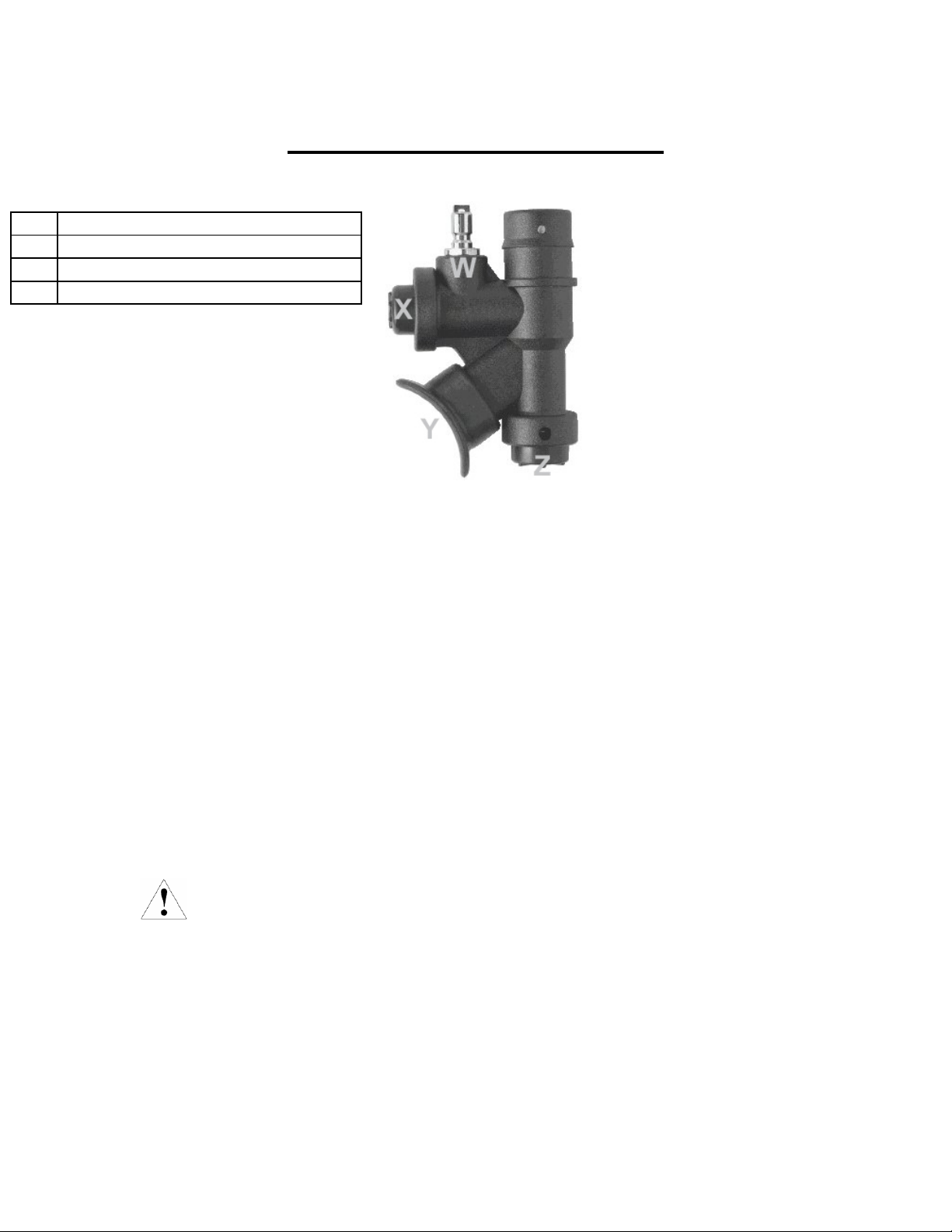
•Improper use of the oral Inflation/ Deflation or dump valve assemblies may allow
water to enter the BC with a subsequent reduction in buoyancy. Reducing
buoyancy can cause a loss of buoyancy control resulting in serious injury or
death.
•Temperature conditions for use (1 to 40 degrees C / 34 to104 degrees F)
•Limitations of dimensions of cylinders (20L single cylinder, or Twin 15 litre
cylinders)
•This is not a lifejacket it does not guarantee a head up position of the wearer at the
surface.
•DO NOT depend on any Hollis BC to save your life under any circumstances.
•Prior to each dive, inspect and test your BC for proper operation. If any part does
not function properly, DO NOT USE!
•In an emergency, Hollis BC’s may not provide face-up flotation in all cases for all
persons.
•DO NOT inhale gases from within any Hollis BC.
•On the Hollis dual bladder, the bladder against the diver’s back is the primary
bladder. Do not inflate both bladders at the same time, this could decrease the
overall lift provided by the bladder.
•If you do not fully understand how to use your Hollis BC, or if you have any
questions regarding its functions, you should seek instruction in its use from your
authorized Hollis dealer before you utilize this product.
•Read and understand the owner’s guide completely before diving with any Hollis
BC system.
•It is the diver’s responsibility to assure that fully configured, ready to dive
systems are able to achieve neutral buoyancy at the beginning and end of any
dive. Adding Non-Drop weights or switching from a single cylinder configuration
to twin cylinder configuration can add significant in water weight.
5

BCD Systems
Hollis offers two traditional style Buoyancy Compensator Device systems. It is
important when choosing a BCD that there is enough buoyancy to float the diver and
equipment at the surface. Hollis BCD Systems are designed for traditional diving.
Adding non ditch-able weights can add significant in water weight. It is the diver’s
responsibility to ensure adequate lift for the gear configuration being used.
Our BCDs are constructed with a 1000 Denier Cordura w/ PU Lamination Outer Shell
and 15mm Urethane Internal Bladder or better. Each BCD also comes standard with a 1”
diameter corrugated hose with the Hollis power inflator. Corrugated hoses are offered in
a variety of lengths for the diver to choose from to customize their system.
BCD systems offered by Hollis:
•ATS – SM & MD 34 lbs (15.4 kg) Lift LG & XL 44 lbs (20 kg) Lift
part # 208.1100.00X
•HD 100 – SM & MD 36 lbs (16.3 kg) Lift LG & XL 38 lbs (17.2 kg) Lift
part # 208.1150.00X
ATS HD 100
6

BC Bladder Systems
Hollis offers a variety of bladder systems to match any diver’s needs. It is important
when choosing a bladder that there is enough buoyancy to float the diver and equipment
at the surface. Adding non ditch-able weights or switching from a single cylinder
configuration to twin tank configuration can add significant in water weight. It is the
diver’s responsibility to choose a bladder appropriate to the needs of his configuration.
All of our bladders are constructed with a 1000 Denier Cordura w/ PU Lamination Outer
Shell and 15mm Urethane Internal Bladder or better. Each bladder also comes standard
with a 1” diameter corrugated hose with the Hollis power inflator. Corrugated hoses are
offered in a variety of lengths for the diver to choose from to customize their system.
Bladder systems offered by Hollis:
•S25– Single Tank Bladder 25 lbs (11.3kg) Lift part # 208.1251.025
•S38 – Single Tank Bladder 38 lbs (17.2kg) Lift part # 208.1251.038
•X37 – Double Tank Bladder 37 lbs (16.8kg) Lift part # 208.1250.037
•X55 – Double Tank Bladder 55 lbs (24.9kg) Lift part # 208.1250.055
•BAC 65 – Double Tank Bladder 65 lbs (29.5kg) Lift - part # 208.1250.060
Removable bungee included
•BAC 85 – Double Tank Bladder 85 lbs (38.6kg) Lift - part # 208.1250.085
Removable bungee included
•BAC D85 – Double Tank Dual Bladder System part # 208.1252.085
85 lbs (38.6) Lift Each – removable bungee included
S25 S38 X37 X55
No Bungee No Bungee
BAC 65 BAC 85 BAC 85D
All Hollis Bladders are designed to be used with the following Hollis Harness Systems:
Solo – Switchback – Elite 2 – HTS 2
7

NOTE: For the 85lb (38.6kg) lift Bladders, Clause 5.5.2 of CE Inflation test with
mechanical device did not pass. Maximum buoyancy was not achieved in 20 seconds
(using a 7 Bar (100 psi) IP). However, maximum buoyancy was achieved in 24 seconds
(using a 7 Bar (100 psi) IP) and SGS has accepted this inflation rate within safe limits for
a device of this size.
Pull Dump
(used on ATS, HD 100, S25, S38 v.2, X37, X55, BAC 65, BAC 85, BAC D85)
All Hollis bladders have a lower right pull dump w/ knob (Fig.1) that can be removed and
knotted for a more streamline system. To remove the pull knob, slide the knob back on
the cord to expose the knot (Fig.2). Untie the knot and slide the knob off the cord and
then retie the knot on the cord Fig.3). To dump air from the bladder, pull lightly on the
cord. Inspect the pull dump regularly to make sure it is working properly and is not
sticking or leaking.
Fig.1 Fig.2 Fig.3
Bungee Cords
(used on BAC 65, BAC 85, BAC D85)
Bungee cords are elastic bands that are used to keep the bladder more streamlined and
compact on the diver. All Hollis bungeed bladders have the option of removing the
bungee. First unclip the bungee from each side of the bladder on the lower inside D-rings
(Fig.4). Remove the clip from one end of the bungee by pulling the shoulder back and
releasing the tabs (Fig.5 & 6). Then pull the bungee through the guides (Fig.7). It is
recommended to reattach the clip to the bungee so you do not lose it.
Fig.4 Fig.5 Fig.6 Fig.7
8

Installing BC Inflator
Quick Disconnect Hose
(used on ATS, HD 100, S25, S38 v.2, X37, X55, BAC 65, BAC 85, BAC D85)
Low pressure (LP) and high pressure (HP) port thread sizes are different, making
incorrect installation of hoses unlikely. However, to avoid damage or personal injury that
may occur due to incorrect installation, Hollis strongly recommends having hoses
installed professionally by an Authorized Hollis Technician. If this is not possible,
proceed as follows.
Installing Hoses:
After having determined the preferred orientation and the correct Low Pressure Port –
•Remove the port plug from the port to be used by turning it counter clockwise
with a 5/32" hex key. Save the port plug for possible future use.
•Lightly lubricate the hose-end threads and o-ring with Tribolube-71 or Christo-
Lube MCG111 lubricant (silicone grease is acceptable only if the regulator is not
intended for use with nitrox).
•Thread the hose clockwise into the port until secure, and then tighten it with an
open end wrench 9/16 in (or 1/2 in) of the appropriate size to a torque of 40 in-lbs.
•After all hoses are connected, test the complete regulator assembly by attaching it
to an appropriate tank, pressurizing the system, and carefully listening for leakage
of breathing gas.
9

BC Inflator System Use
(used on ATS, HD 100, S25, S38 v.2, X37, X55, BAC 65, BAC 85, BAC D85)
W LP Hose Connector
X Power Inflator Button
Y Mouthpiece
Z Deflate/Manual Inflation Button
Hollis Inflator Systems are designed for working pressures of 120 psi (8 Bar) minimum,
140 psi (9Bar) nominal and 160 psi (11 Bar) maximum.
With the Hollis Inflator you can inflate the BC by two methods, Manually and Power
Inflation.
Manual Inflation:
To manually inflate the BC, depress the Manual Inflation Button and blow into the
Mouthpiece. Be sure to release the Manual Inflation Button before you remove your
mouth from the Mouthpiece to ensure you do not lose any air through the Mouthpiece.
Repeat until desired buoyancy is achieved.
Power Inflation:
To power inflate the BC, depress the Power inflator button. This can only be achieved
when the Low Pressure Inflator Hose is connected and under pressure from the regulator
1st stage. Use short bursts of air to inflate the BC being careful not to add too much air.
Note: Have an authorized Hollis technician attach the LP hose to the regulator 1st stage.
WARNING: If you depress the Power Inflator fully, the BC will inflate rapidly.
Be careful not to overinflate the BC causing an unwanted rapid rise towards the surface.
Deflating the BC through the Inflator Mouthpiece:
To deflate the BC using the Inflator, hold the Power Inflator higher than the top of the BC
and depress the Deflate button to release the air. The Mouthpiece must be higher than the
BC to ensure complete deflation of the BC. While underwater, be sure to release the
Deflate button before all air is released to prevent water from entering the BC.
10

RE (Rapid Exhaust) Valve Shoulder Dump:
You can only dump air from the shoulder if you have an attached RE Valve available as a
separate option (Standard shoulder elbows will not dump air in this manner). In an
upright position with your shoulders towards the surface, pull on the corrugated inflator
hose from the Power Inflator end. This will open the RE valve on your shoulder and will
release the air.
Attaching the LP (Low Pressure) Inflator Hose:
With the inflator Hose attached to the regulator, connect the regulator to a pressurized
SCUBA tank. Grasp the QD (Quick Disconnect) end of the LP Inflator Hose and pull
back the coupling release and press it onto the connector on the Inflator System and let go
of the coupling. Make sure the LP Hose is securely attached before pressurizing the
regulator system. Pressurize the regulator system by slowly opening the tank valve.
Now press the Power Inflator Button until you hear air flowing into the BC.
Buoyancy Control:
Using the inflation and deflation methods described will help you maintain neutral
buoyancy throughout your dive at different depths. A diver who practices Buoyancy
Control can hover in mid water with varying depth, wetsuit compression or weights’.
Having good Buoyancy Control will allow a diver to shed unnecessary lead weight and
use less energy creating a longer, more relaxed dive.
11

BC Harness Systems
Solo Harness
Solo Harness Kit:
•Continuous Weave One Piece Harness System w/ 2in (5.1cm) Crotch Strap
•7 Loose D-Rings w/ keepers to be Custom Placed by Diver (Suggested 2 on Each
Shoulder, 1 on Each Waist and 1 on the Crotch Strap.
•2in (5.1cm) Stainless Cam Buckle
•Shoulder Pads
•Backplate not included
Solo Harness Kit Complete Assembly Rear View
12

Solo Harness
Shoulder Straps: Insert main harness webbing through top slot of plate that would be
on your right shoulder. Make sure the grommet is in front of the plate with about 6in
(15.2cm) of webbing between the grommet and the front of the plate (Fig.8). Now insert
grommet side of webbing back through angled slot next to the top slot and pull webbing
through so the grommet is now on the back side of the plate (Fig.9). Pull the webbing
across the back of the plate and insert the webbing though the angled slot on the opposite
side of the plate. Adjust the webbing so the grommet is centered with the bolt hole in the
plate (Fig.10). Now from the front, pull webbing back through the top slot so the
webbing mirrors itself on both shoulders (Fig.11). Place plate so that the front is facing
forward and bring webbing to the front (Fig.12).
Fig.8 Fig.9 Fig.10
Fig.11 Fig.12
13

Shoulder Pads: Make sure when installing the shoulder pads that they curve away from
the center of the backplate; so that they wrap naturally around your body. Each pad has 3
elastic slots that the webbing must weave through (Fig.13). Between the elastic slots are
2 spaces for included D-rings. Slide the pad on to the harness webbing to where you feel
it will sit best on your shoulder and insert D-rings with slide between each elastic slot to
hold shoulder pad in place (Fig.14). Pads can be adjusted later when harness is complete.
Repeat same process on opposite shoulder (Fig.15).
Fig.13 Fig.14 Fig.15
Waist Straps: Making sure the shoulder straps contour in and around the body, pull
webbing through lower inside angled slots. Insert webbing through metal keeper on the
backside of the backplate and then back through lower outside angled slots so the
webbing is on the front side of the plate (Fig.16). Adjust webbing so there is enough
slack in the shoulder area to don harness. Additional adjustments can be made when
harness is complete. If desired, included D-rings can be inserted on either side of the
harness waist strap (Fig.17 & 18). D-rings can be adjusted to any position on the waist
webbing as desired.
Fig.16 Fig.17 Fig.18
14

Crotch Strap: Take the side of the crotch strap that is not looped; insert the slide/keeper
leaving about 8in (20.3cm) of webbing between the slide and the end of the webbing.
Then weave webbing through the larger slot at the center of the backplate’s bottom and
back through the slide/keeper (Fig.19, 20 & 21). This is where adjustment to the crotch
strap will be made. The looped end will thread onto the waist strap.
Fig.19 Fig.20 Fig.21
Your Solo harness is now complete.
15

Switchback Harness
Switchback Harness Kit:
•Left side waist webbing with left side sternum strap on SS round ring and female
half of left shoulder buckle with attached D-ring. 1 SS D-ring with slide/keeper.
•Right side waist webbing with right side sternum strap on SS round ring. 1 SS D-
ring with slide/keeper and SS waist cam buckle.
•Crotch strap with attached SS round ring, plastic buckle and 2 plastic slides.
•Shoulder webbing with centered grommet. Male end of left shoulder buckle. 5
plastic slide/keepers with 3 bent SS D-rings.
Left Waist Webbing Right Waist Webbing Crotch Strap Shoulder Webbing
16

Switchback Harness
Shoulder Straps: Insert shoulder harness webbing through top slot of plate that would
be on your right shoulder. Make sure the grommet is in front of the plate with about 6in
(15.2cm) of webbing between the grommet and the front of the plate (Fig.22). Now
insert grommet side of webbing back through angled slot next to the top slot and pull
webbing through so the grommet is now on the back side of the plate (Fig.23). Pull the
webbing across the back of the plate and insert the webbing though the angled slot on the
opposite side of the plate. Adjust the webbing so the grommet is centered with the bolt
hole in the plate. Now from the front, pull webbing back through the top slot so the
webbing mirrors itself on both shoulders (Fig.24). Webbing will naturally cross creating
the cross-back feature of the Switchback harness system (Fig.25).
Fig.22 Fig.23 Fig.24
Fig.25
Waist Webbings: With the female shoulder buckle and sternum strap laid flat facing
away from the plate (Fig.26), inset left waist webbing through lower left inside angled
slot (front to back) and weave back through lower outside angled slot (back to
front)(Fig.26). Repeat the same process with the right waist webbing (Fig.27).
Fig.26 Fig.27
17

At this point the system should look like Fig.28. Using SS slides, insert flat SS D-rings,
one on each side of the waist (Fig.29, 30 & 31). Adjustments can be made later.
Fig.28 Fig.29 Fig.30
Fig.31
Waist Cam Buckle: Insert waist cam buckle on left side webbing. See “BC Waist Cam
Buckle” section for recommended buckle weave. At this point the system should look
like Fig.32.
Fig.32
18

Crotch Strap: Take the side of the crotch strap that is not looped; insert the
slide/keeper, leaving about 8in (20.3cm) of webbing between the slide and the end of the
webbing. Then weave webbing through the slot at the center of the backplate’s bottom
and back through the slide/keeper (Fig.33, 34 & 35). This is where adjustment to the
crotch strap will be made. The looped end will thread onto the waist strap.
Fig.33 Fig.34 Fig.35
Left Shoulder Installation: Install plastic slide on each shoulder so there is about 3in
(7.6cm) between the plate and the slide (Fig.36). The harness will criss-cross, so the
webbing from the right shoulder of the plate will go over the left shoulder of the diver
(shoulder release buckle side). Using 1 plastic slide, install 1 bent SS D-ring on the left
shoulder side (Fig.37 & 38) (Adjustments can be made later). Then install the male side
of the shoulder buckle, positioned in the center between the distance from the plate to the
end of the webbing (Fig.39). Then weave the webbing back through the plastic slide with
the D-ring (Fig.40). Adjustments can be made later.
Fig.36 Fig.37 Fig.38
Fig.39 Fig.40
19

Right Shoulder Installation: The harness should criss-cross so the webbing from the
left shoulder of the plate will go over the right shoulder of the diver. Using the 2 plastic
slides, install the 2 bent SS D-ring on the right shoulder side (Fig.41) (Adjustments can
be made later). Then weave the webbing through the SS round ring of the right side
waist webbing (make sure the waist webbing is curved correctly so it contours around the
body and the sternum strap is on the correct side facing in). Positioned the SS round ring
in the center between the distance from the plate to the end of the webbing, then weave
the webbing back through the plastic slides with the D-rings (Fig.42, 43 & 44).
Adjustments can be made later.
Fig.41 Fig.42 Fig.43
Fig.44
Weave extra webbing from both shoulders through plastic slides 3in (7.6cm) from plate
(Fig.45 & 46). Then fasten left shoulder buckle (Fig.47) (make sure the waist webbing is
contoured correctly so it curves around the body and the sternum strap is on the correct
side facing in).
Fig.45 Fig.46 Fig.47
Your Switchback harness is now complete.
20
This manual suits for next models
16
Table of contents
Popular Safety Equipment manuals by other brands

NUOVA ELETTRONICA
NUOVA ELETTRONICA MCS instruction manual

Fiessler
Fiessler ULCT operating manual

Zero
Zero RCSL00M quick start guide

STRUMIN
STRUMIN SYSTEMIC EDGE PROTECTION manual

Bodypoint
Bodypoint EvoFlex EBE100 Installation and user instructions

Innova
Innova XTIRPA IN-8002 Instruction and safety manual