Wolo NEXGEN 8504 Series User manual

NEXGEN 40 WATT / 4 OUTLET 12-24 VOLT
POWER SUPPLY & LED LIGHT KIT
15 Different Light Patterns 8504 SERIES
INSTALLATION INSTRUCTIONS
Your purchase of Wolo’s NEXGEN LED light system is the perfect choice to compliment your vehicles
emergency warning lights. Wolo’s LED kits are manufactured with the finest materials. Each light is tested to
meet our high standards to ensure that all functions work perfectly. Our quality workmanship and components
are Wolo’s assurance that this product will provide years of dependable service. If you need help using or
installing your new Wolo warning light, our technicians are available to answer your questions, Monday thru
Friday, from 9 AM to 4 PM EST at: 888-550-4676.
Before installing the LED it is important to read these instructions completely. The lives of people are
dependent on the proper installation. The person installing the power supply must have advanced knowledge
of the proper method of installing emergency warning lights to a vehicle as well as knowledge of the vehicle's
electrical system. Again, read this manual completely and note any messages marked ‘‘IMPORTANT” or
‘‘WARNING”. A safe installation will prevent serious injury or damage to the vehicle.
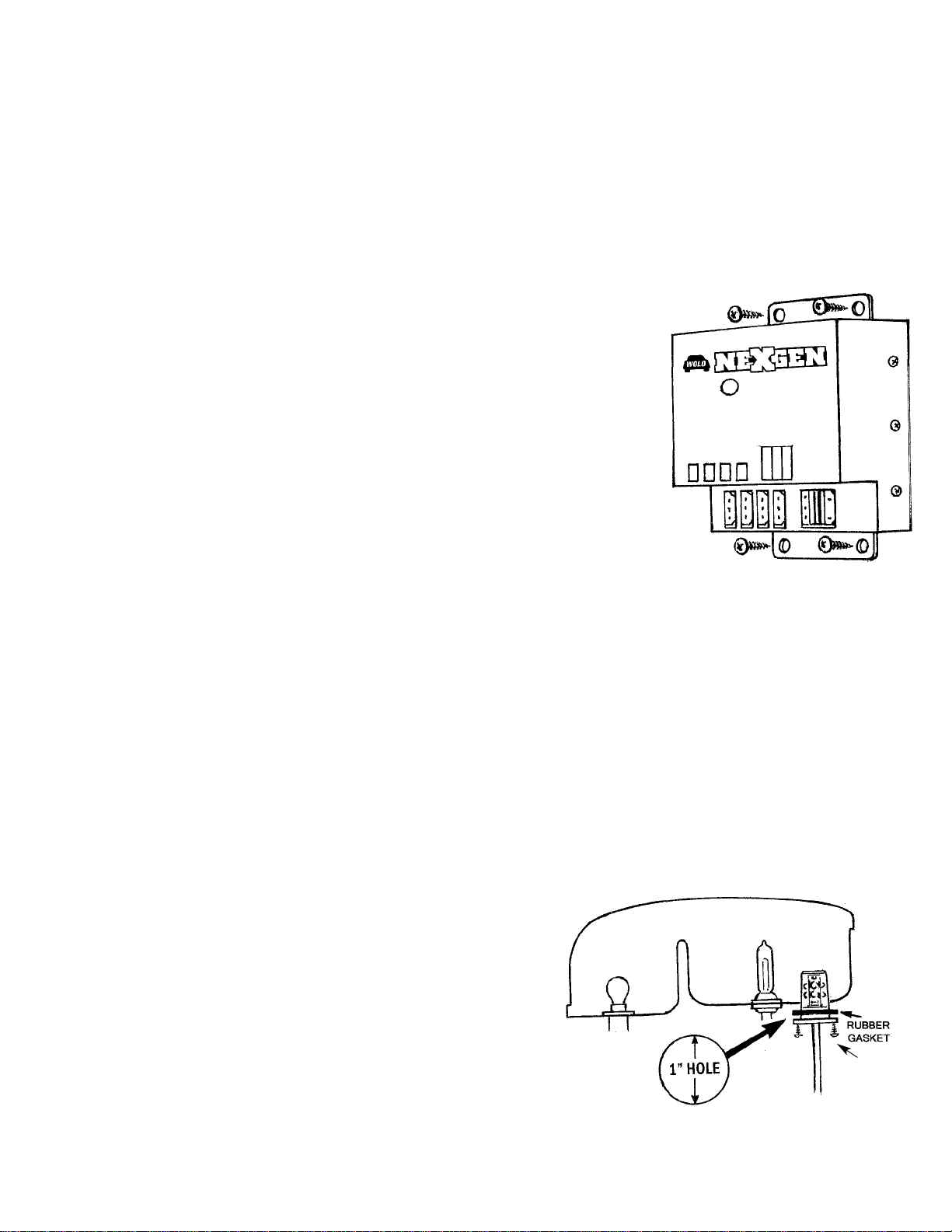
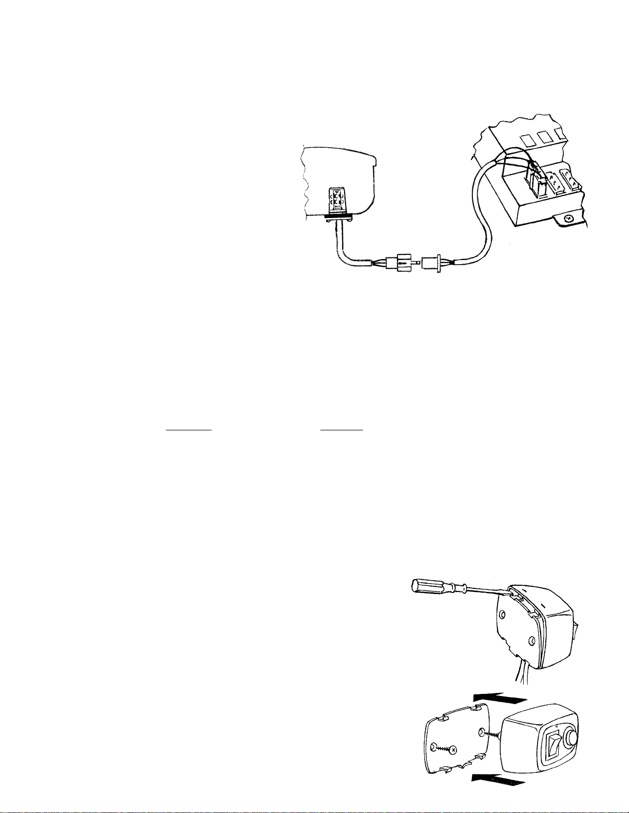
NEXGEN is completely wired and does not require any wiring inside the power supply. There are four (4)
power cables included in the kit; two (2) that are 3 meters / 9.8 ft. in length for installation in front of vehicle
and two (2) that are 5 meters / 16.4 ft. in length for installation in rear of vehicle. Also included in the kit is a
control panel, dash mountable with an on/off switch and a push button switch to change the LED light pattern,
all which is required for a successful installation.
Installation of NEXGEN requires drilling to the vehicle. The installer must carefully inspect both sides of any
location that will be drilled to ensure that there are no components, wires and or any vehicle parts that could
be damaged when drilling.
IMPORTANT: Always de-burr any drilled holes to ensure that there are no sharp edges. Install a rubber
grommet into all metal holes that the wires are being routed through.
Always refer to the vehicle’s shop manual for the deployment location of the air bags. Never install the control
panel switches, wires and/or components in the deployment area of any air bag. Improper installation could
reduce the effectiveness of the vehicle's air bag system and/or project an object that could cause serious
personal injury or death to the driver or passenger. The user/installer assumes all responsibility to properly
access a safe mounting location for the switch control panel, so to provide ultimate safety to the driver and
passengers inside the vehicle.
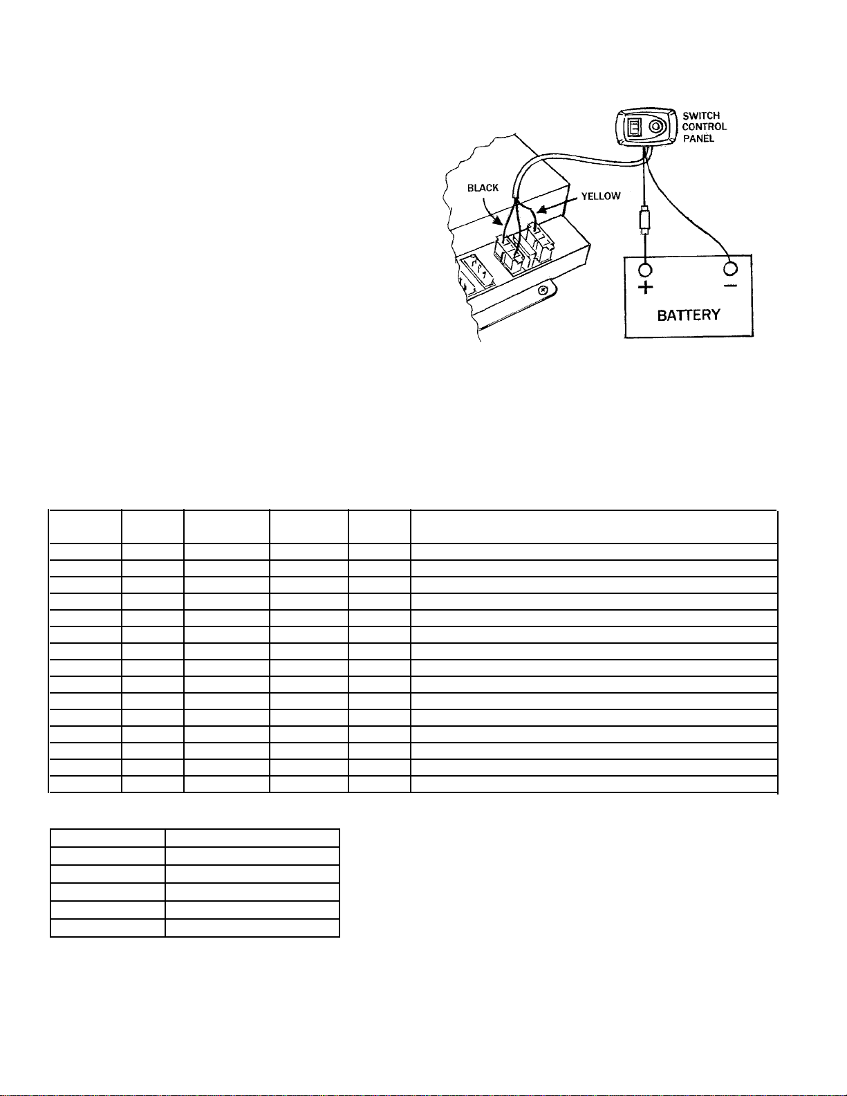
All NEXGEN models produce both low voltage and low current. To operate this product at peak performance,
the black wire should always be connected directly to the (-) negative battery post, or under a metal body bolt.
If the length of the black wire needs to be made longer, use a minimum 18 gauge or heavier.
The vehicle operator and/or maintenance department should inspect the light system frequently to ensure that
all LED heads are functioning and are securely held in the vehicle’s light assembly.
These installation instructions should always be kept and stored in a safe location so that they can be referred
to when information, maintenance or reinstallation is required. Failure to follow all safety precautions and
installation procedures as outlined in these instructions could result in property damage to the vehicle, serious
injury or death to you or others.

WARNING
• All 8504 models contain four (4) LED heads. At a close distance, never look directly at the heads when
the power supply is turned on. Momentary blindness and/or permanent eye damage could occur.
• The power supply produces LOW VOLTAGE. Never touch or remove any of the LED heads while in
operation. Wait no less than 5 minutes after disconnecting the power supply from it’s power source
to attempt to handle LED heads or troubleshoot.
• DO NOT connect the power supply to the vehicle’s battery or any other power source until ALL LED heads
are mounted and wired to power supply.
FAILURE TO FOLLOW ALL SAFETY WARNINGS AND INSTRUCTIONS COULD RESULT IN DAMAGE TO
PRODUCT, VEHICLE OR COULD CAUSE SERIOUS INJURY TO YOU AND
PASSENGERS!
INSTALLATION OF POWER SUPPLY Fig. A
CAUTION
The power supply is NOT waterproof and must be mounted in a dry location
inside vehicle. The power supply should NEVER be exposed to weather
conditions such as rain, snow, water and etc. The power supply should be
mounted in a well-ventilated location. Never mount the power supply in the
vehicle’s engine compartment near a heater duct or close to the engine
components that will get hot.
IMPORTANT
The power supply should be mounted on a metal surface to help prevent radio
interference and to act as a heat sink. Doing such will reduce heat from the power supply protecting the
electronic components. Make sure that the mounting surface does not get hot from normal vehicle operation.
1. Place the power supply on the mounting surface. Using the mounting bracket as a template, mark the four
hole locations onto the mounting surface and drill to size using a 1/8” drill.
2. The installer must carefully inspect both sides of the selected mounting location to ensure that there are no
components, wires and or any other vehicle part that could be damaged by the drilling.
3. Position the power supply to the mounting surface and secure using the sheet metal screws provided.
INSTALLATION OF THE LED HEADS INTO THE HEADLIGHT and TAILLIGHT ASSEMBLIES
Fig. B
IMPORTANT
• The LED heads are going to share the same reflector and lens as the headlight and taillight. Before drilling
any hole into the light assembly you must make sure that the
position of the LED head will not interfere with the operation or
visibility of the vehicles original equipment light.
• The LED head must have a minimum of one (1) inch of open
space from the OEM factory bulb.
• Never install the LED head directly above the OEM factory
bulb.
• Before drilling the hole for the LED head, the installer should
remove the OEM factory light assembly and reflector.
4. Select a position in the headlight or taillight assembly that is
flat to ensure a good watertight seal with the rubber gasket
that is placed between the LED head and the light assembly.
5. Using a 1” hole saw, cut a hole into the light assembly in the selected location and de-burr hole.
6. Install the LED head into light assembly.
Fig. A
Fig. B
1/8”
SCREW

7. There are two holes in the metal rim of the LED head. Use the metal rim as a template and mark the two
holes locations on the light assembly housing and drill to size using an 1/8” drill.
8. Clean the interior of light assembly and lens of any dust or filings, which may have developed during cutting
the hole.
9. Re-install the OEM factory light assembly and reflector.
10. Place the rubber gasket around the LED head
and install the head into the one (1) hole and
secure using the self-tapping screws
(provided).
11. Repeat the same installation procedure for
the remaining LED heads.
WIRING LED HEADS Fig. C
IMPORTANT: To prevent damage to the power
supply, DO NOT connect any power source until
all of the LED heads are completely wired to the
power supply. All 8504 models come with four (4)
cables that are used to connect the LED heads to
the power supply. Each cable has two female plugs, one at each end. The plugs are different and will only
connect to its mate, either the LED head, or power supply.
12. Two of the cables are 3 meters / 9.8 ft. in length and should be used to connect the LED heads installed in
the front light assemblies to the power supply position L1 & L2.
13. Two of the cables are 5 meters / 16.4 ft. in length and should be used to connect the LED heads installed
in the rear light assemblies to the power supply position L3 & L4.
NOTE: If you need to lengthen the rear cables, see chart below for proper wire gauge.
16-30 ft. 31-50 ft.
Use 18 Gauge or heavier Use 16 Gauge or heavier
MOUNTING SWITCH CONTROL PANEL
Using double face tape or screws
TAPE METHOD
14. Select a mounting location for the control panel that is easy to reach. IMPORTANT: Be sure that the switch
control panel or its wires will not interfere with air bags or the driver’s vision.
15. Using the double-sided foam adhesive tape provided, mount the control panel to selected location. Make
sure that mounting surface is free from dust, wax etc. Aclean surface is necessary so that double-sided
tape will hold properly.
IMPORTANT: THEADHESIVE HOLDING POWER BECOMES
MAXIMUM IN ABOUT 24 HOURS. LIMIT MOVING OR PUTTING
PRESSURE ONTO THE KEYBOARD UNTIL THEN.
SCREW METHOD Fig. D & E
16. Remove the control panel’s backing plate using a flat tip screwdriver.
17.Using the backing plate as a template, mark the two hole locations
onto the mounting surface where the switch panel will be mounted and
drill to size using a 3/16” drill. IMPORTANT: The installer must
carefully inspect both sides of the mounting location before drilling any
holes to ensure that there are no components, wires and or any
vehicle part that could be damaged by drilling.
18. Position the backing plate on the mounting surface and secure using
the two sheet metal screws provided that have the countersunk head.
19. The control panel is carefully pushed onto the backing plate.
Fig. C
Fig. D
Fig. E
HOLE SIZE
3/16”

WIRING SWITCH CONTROL PANEL TO 12-24 VOLTS. Fig. F
WARNING: The power supply has an external 5-amp
fuse to protect its internal circuit. The 5-amp in-line
fuse attached to the red wire must be connected “AT A
POWER SOURCE” so to protect the wire connection
between the power source and power supply.
20. BLACK WIRE: Is connected to ground (-). Secure
the BLACK to the negative battery post or under any
metal body bolt. Make sure that the METAL surface
around the bolt that secures the wire is clean of rust
and paint so to make a good electrical connection.
21. RED WIRE: Is connected to 12-24 volts (+) positive.
Using the inline fuse provided, connect the red wire
to the vehicle’s fuse block or (+) positive battery
post. Remove fuse from the inline fuse holder until
all wiring is completed.
22. The plug with the YELLOW wire is connected to the power supply in the position marked “CONTROL’’.
23. The plug with the RED & BLACK wires is connected to the power supply in the position marked
“12-24 VOLTS”.
24. Inspect all wiring and make sure all connections are secure. Install fuse back into the inline fuse holder.
INSTALLATION IS COMPLETE
Position the on/off switch to “ON“. Press and release the push button to change the light pattern.
PATTERN HEAD HEAD HEAD HEAD LED HEAD SEQUENCE
1 2 3 4
1 STEADY STEADY STEADY STEADY ALL
2 STEADY STEADY DF DF CONTINIOUS
3 DF DF STEADY STEADY CONTINOUS
4 DF DF DF DF ALL
5 SF SF SF SF 1&2 / 3&4 ALTERNATE
6 QF QF QF QF ALL
7 TF TF TF TF ALL
8 TF TF TF TF 1&2 / 3&4 ALTERNATE
9 TF TF TF TF ALL
10 SF SF SF SF ALL FAST
11 SF SF SF SF ALL
12 DF DF DF DF 1&2 / 3&4 ALTERNATE
13 SF-TF SF-TF SF-TF SF-TF 3-SINGLE FLASHES THEN 3 TRIPLE FLASHES ALTERNATE
14 SF-TF SF-TF SF-TF SF-TF 3-SINGLE FLASHES THEN 3 TRIPLE FLASHES ALTERNATE
15 STF STF STF STF 1&2 / 3&4 ALTERNATE
DESCRIPTION OF LIGHT PATTERN
SF SINGLE FLASH
DF DOUBLE FLASH
TF THRIPLE FLASHES
QF QUAD FLASH
STEADY NO FLASH
STF SLOW TO FAST
Fig. F

Warranty
Wolo Manufacturing Corporation (“Wolo”) warranties to the original purchaser, for three months from the date of purchase,
that this product is free from defects in workmanship and materials. If there is such a proven defect, Wolo, at its option, will
either repair or replace the item free of charge, if it is returned to Wolo within three months from the date of purchase
together with proof of purchase as described below. Wolo reserves the right to inspect any defect prior to settling any
warranty claim by repair or replacement. This warranty is limited as above provided and Wolo will not be responsible for
fire or other casualty or accident, due to neglect, abuse, abnormal use, modifications, faulty installation of this product, or
natural causes.
ANY EXPRESSED WARRANTY NOT PROVIDED HEREIN IS EXCLUDED AND DISCLAIMED. THE IMPLIED WARRANTIES
OF MERCHANTABILITYAND OF FITNESS FOR A PARTICULAR PURPOSE ARE EXPRESSLY LIMITED TO A TERM OF
THREE (3) MONTHS FROM DATE OF PURCHASE. UNDER NO CIRCUMSTANCES SHALL WOLO BE LIABLE TO
PURCHASER OR ANY OTHER PERSON FOR ANY SPECIAL OR CONSEQUENTIAL DAMAGES, WHETHERARISING OUT
OF BREACH OF WARRANTY OR OTHERWISE.
To obtain warranty service, return the product prepaid, and include the original bill of sale showing the date of purchase. Provide
with the return a brief description of the problem. Also, include with the return a check or money order in the amount of $10.00 to
cover return shipping. Mail to:
Wolo Manufacturing Corp.
One Saxwood Street, Deer Park, NY 11729
All Rights Reserved.
SPECIFICATIONS
Input Voltage: 12-24 VDC
Current: 1.54 amps@ 12.5 VDC
LED Heads: Each contain 8 GEN 3 / 1-Watt Super Bright LEDs
Power Supply Maximum Output: 40-Watts
Flash Patterns: 15
Included: Two Cables 3 meters / 9.8 ft. length with locking connectors
Included: Two Cables 5 meters / 16.4 ft. length with locking connectors
Included: Switch control panel pre-wired
Power Supply Dimension: L 5-1/2 in. x W 5-3/8 in. x H 1-3/4 in.
Table of contents
Popular Lighting Equipment manuals by other brands

IOTA
IOTA ILBLP CP HE SD instruction manual

Candela
Candela ELR EDGE-LIT installation manual

HEPER
HEPER PRIFMA ML EVO 1 Duo Installation & maintenance instructions

Larson Electronics
Larson Electronics LM-25-3S-EW-THM-12VDC manual

Glow Bricks
Glow Bricks Lego LandRover Classic Defender 90 10317 installation guide

SELETTI
SELETTI MY TINY MOON manual

Etlin-Daniels
Etlin-Daniels EC302WHM-A13-BB-GU-10RC quick start guide

BEKA Schreder
BEKA Schreder SOLARPOLE quick start guide

AllioLight
AllioLight TPS-System 2051 user manual

DS Produkte
DS Produkte BG-F-0080 instructions

Home Accents Holiday
Home Accents Holiday TY461-2011-1 Assembly instructions

Beghelli
Beghelli 84-00 Series Mounting instructions