WoodFast M305X User manual

FOR YOUR SAFETY
READ ALL INSTRUCTIONS CAREFULLY BEFORE USING THIS MACHINE
Wood Lathe
Instruction Manual
Model: M305X
Ver. QCR-07-93-40

M305X
305mm
240mm
406mm
1/2HP, 230V/50Hz
Electronic Variable – High, Medium and Low ratio
400~950,650~1700,1500~3850rpm
M33mm x 3.5p
M30mm x 3.5p
MT2
MT2
9.6
63.5mm
980 (L) x 200 (W) x 415 (H) mm
Model Number
Swing Over Bed
Swing Over Tool Rest Base
Working Distance Between Centers
Motor
Speeds
Speed Ranges
Spindle Thread (Europe)
Spindel Thread (Australia)
Headstock Taper
Tailstock Taper
Hole Through Spindle
Tailstock spindle travel
Overall Dimensions
Table of Contents
Specifications
1
Table of Contents
Specifications..........................................................................................................................................1
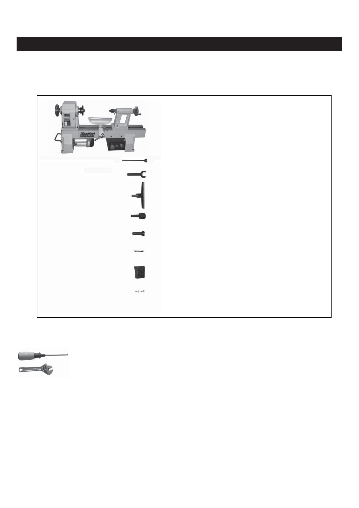
Contents of Package...............................................................................................................................2
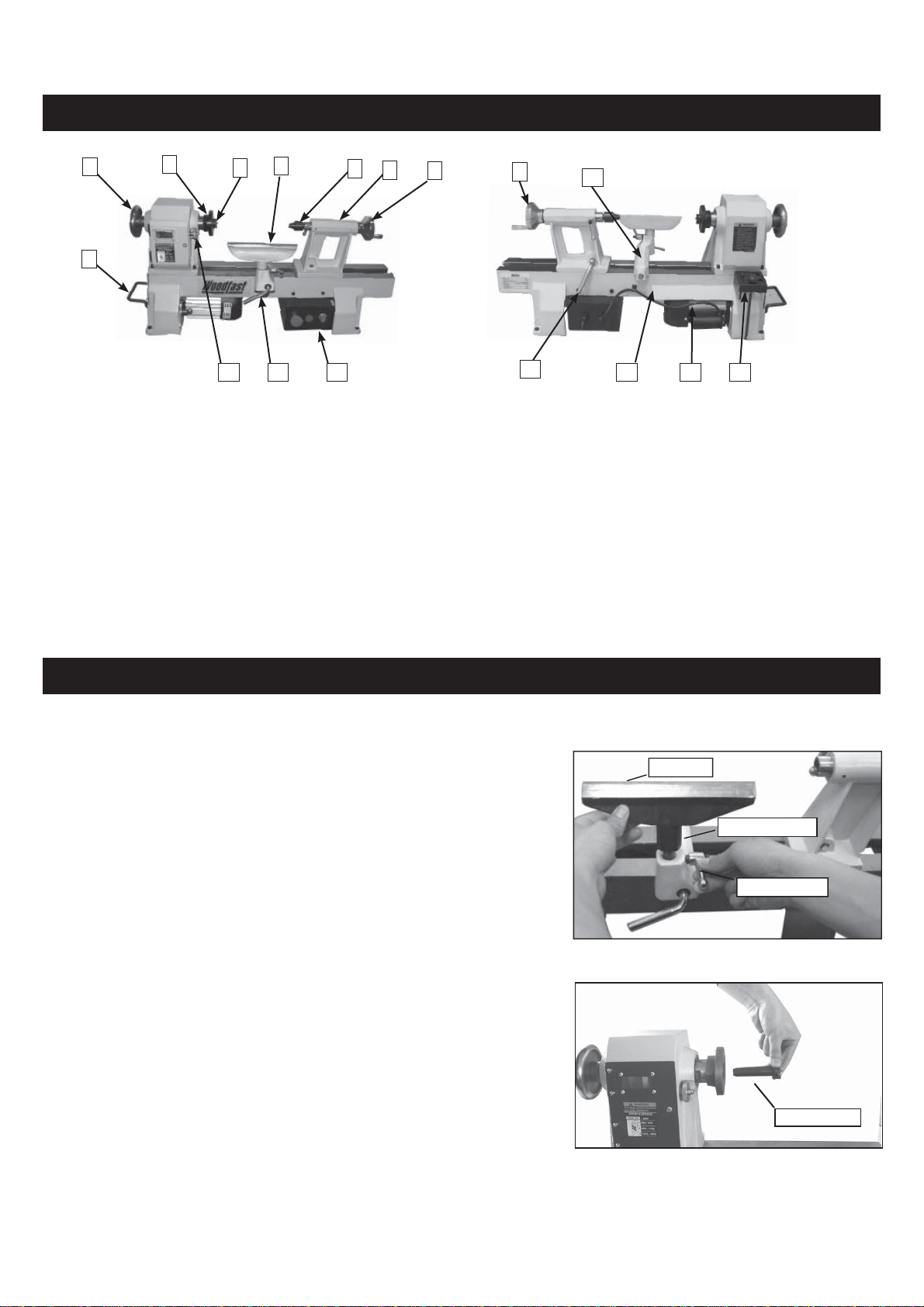
Getting to Know Your Lathe.....................................................................................................................3
Assembly................................................................................................................................................3
Installing the Tool Rest...........................................................................................................................3
Attaching the Spur Center.......................................................................................................................3
Attaching the Live Center........................................................................................................................4
Installing the Faceplate...........................................................................................................................4
Installing the Tool Holder.........................................................................................................................4
Securing the Lathe to a Work surface or Stand........................................................................................4
Adjustments and operations....................................................................................................................5
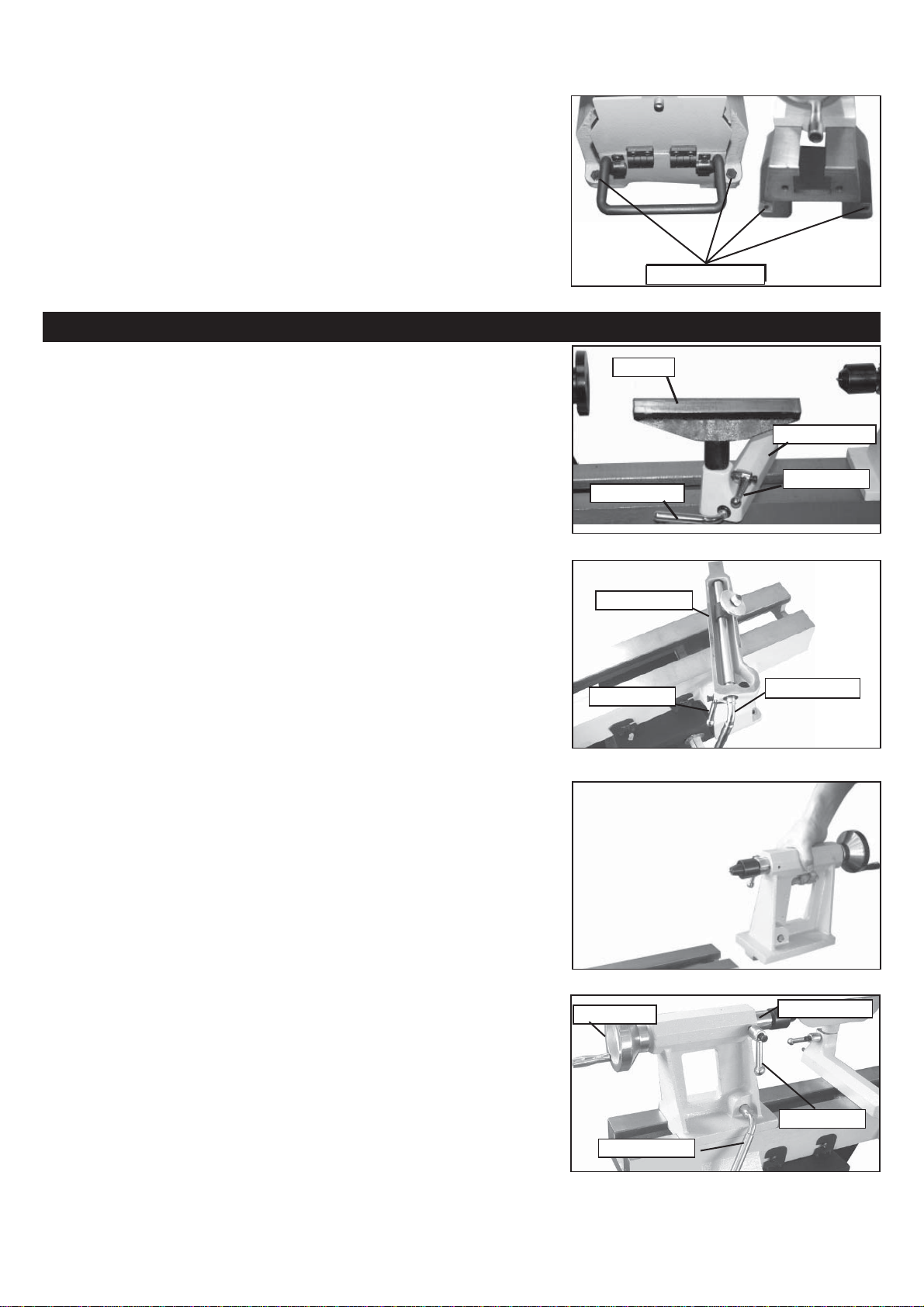
Adjusting the Tool Rest............................................................................................................................5
Adjusting the Tailstock.............................................................................................................................5
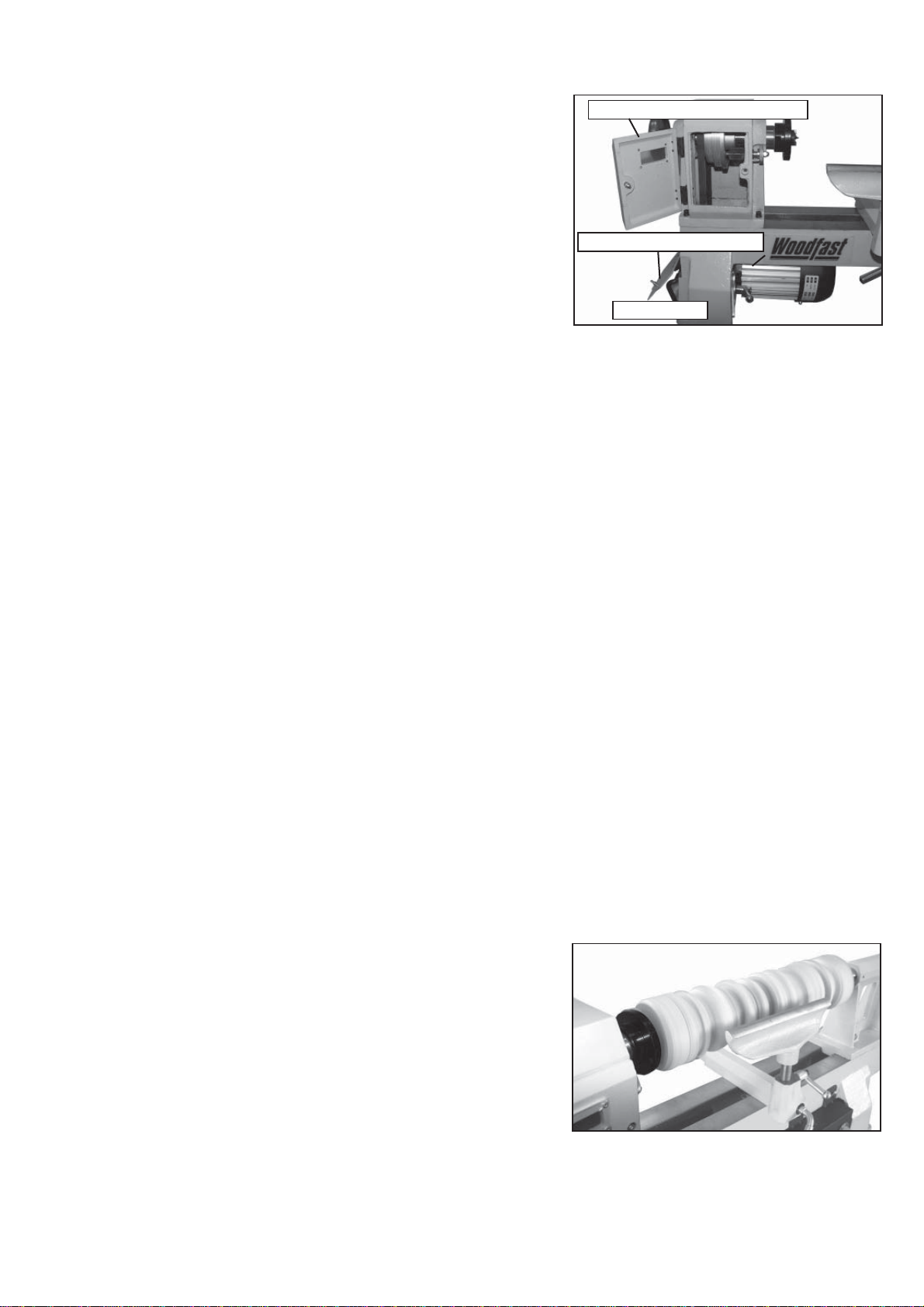
Changing Spindle Speeds.......................................................................................................................6
Typical Operations..................................................................................................................................6
Indexing /Spindle Lock............................................................................................................................7
Maintenance.........................................................................................................................................7
Electrical Requirements..........................................................................................................................8
Wiring Diagram......................................................................................................................................8
How best to use your electronic speed control unit..................................................................................9
Troubleshooting....................................................................................................................................11
Explosion Diagram................................................................................................................................12
Parts List...............................................................................................................................................13

2
Unpacking and Clean-up
1. Carefully lifting the lathe from the carton, and check that all of the components and contents
have been included. Place parts on a protected surface.
2. Clean all rust protected surfaces with kerosene or diesel oil. Do not use; gasoline, paint
thinner, mineral spirits, etc. These may damage painted surfaces.
3. Set packing material and shipping cartons to the side. Do not discard until machine has been
set up and is running properly.
Tools Required for Assembly
Item Description
Phillips Screwdriver
Adjustable Wrench
Contents of Package
Unpack your lathe from its carton and check to see that you have all of the following items. Do not
turn your machine ON if any of these items are missing. You may cause injury to yourself or damage
to your machine.
Unpacking and Checking Contents
Item Description Q’ty
A Lathe..........................................................1
B Knokout Bar................................................1
C Wrench.......................................................1
D Tool Rest.....................................................1
E Live Center.................................................1
F Spur Center................................................1
H Knockout Bar for Spur Center......................1
I Tool Holder...........................................1
J Pan head screw...........................................2

3
The machine must not be plugged in and the power switch must be in the OFF position until the
machine is completely assembled.
Installing Tool Rest On To Lathe Bed
Loosen locking arm and insert tool rest into tool rest
base, adjust height up or down and tighten locking arm.
(See Fig.01)
Getting to Know Your Lathe
Assembly
Locking arm
Tool rest
Tool rest base
Fig.01
1 Lifting handle
2 Handwheel
3 Face plate
4 Spur center
5 Tool rest
6 Live center
7 Tail stock
8 Tailstock handwheel
9 Tailstock spindle locking arm
10 Tool rest base
11 Tool holder
12 Motor
13 Lathe bed
14 Tailstock locking lever
15 Switch
16 Tool rest base locking lever
17 Indexing / Spindle lock
2
1
345678910
11
12
13
14
17 16 15
Spur center
Attaching Spur Center On The Headstock
Insert spur center, with a No. 2 Morse Taper shank,
into the headstock spindle.(See Fig.03)
Fig.03

4
Knockout Bar
The knockout bar is used to remove the spur center from
the headstock spindle. Insert knockout bar into hole at
opposite side from spur center. (See Fig.04)
Fig.04
Knockout bar
Attaching Live Center On the Tailstock
Insert the live center, with a No. 2 Morse Taper shank into
the tailstock spindle. (See Fig.05)
Live center Tailstock spindle
Fig.06
To remove the live center from the tailstock spindle, loosen
locking arm and rotate the hand wheel counter clockwise
to retract spindle into the body of the tailstock. The live
center will be pushed out of the spindle.The knockout bar
is also used to remove the live center from the tailstock
spindle. (See Fig.06)
Fig.05
Locking arm
Installing The Faceplate to the Headstock
Thread the faceplate clockwise on to the headstock
spindle. Engage the spindle lock and stop the spindle from
turning. Tighten the faceplate with the supplied wrench.
(See Fig.07)
Fig.07
Faceplate
Warning: Disengage spindle lock before turning the
machine on.
Installing Tool Holder On the Lathe Bed
Located the tool holder from the carton, and install it onto
the lathe bed with two pan head screws. (See Fig.08)
Pan head screw
Fig.08
Tool holder

Adjusting Tailstock
Loosen the locking lever to move the tailstock along
the lathe bed to the desired position. Tighten the lever.
To adjust clamping action of the tailstock, remove it
from the lathe bed and adjust the nut clockwise to
tighten and counterclockwise to loosen.(See Fig.12)
To adjust the tailstock arm in or out, loosen the locking
arm and turn the handwheel. When the tailstock arm is
in a desired position, tighten locking arm.
(See Fig.13)
Locking arm
Locking lever
Handwheel Tailstock arm
5
Secure Lathe to a Solid Work Surface
The lathe must be attached to a solid work surface or
stand. Four mounting holes are easily accessible at the
base of the lathe. (See Fig.09)
Adjustments and Operations
Adjusting the Tool Rest
The tool rest base can be easily moved along the
lathe bed. Loosen the locking lever counter clockwise,
slide the tool rest base to new position, and tighten the
locking lever clockwise.
To adjust the height of the tool rest, loosen the locking
arm, raise or lower the tool rest, then tighten the
locking arm. (See Fig.10)
Note: Position the tool rest as close to the work piece
as possible.
To adjust the clamping action of the tool rest base,
remove the base and adjust the nut clockwise to
tighten and counterclockwise to loosen.(See Fig.11)
Tool rest
Locking arm
Locking lever
Tool rest base
Locking arm Locking lever
Tool rest base
Fig.09
Mounting holes
Fig.12
Fig.13
Fig.10
Fig.11

6
Changing Spindle Speeds
The lathe features three step motor and Headstock
spindle pulleys. These three drive ratios are used in
conjunction with the electronic variable speed control to
provide maximum power and speed when required.
1, Open both motor pulley and Headstock pulley access
doors.
2, Loosen motor locking arm and raise motor.
3, Move drive belt to selected drive ratio.
4, Lower motor for adequate belt tension and tighten
locking arm.
(Do not apply excessive load onto the belt prior to locking,
as damage may result.)
- High ratio range - (small diameter Headstock pulley
/ large diameter motor pulley) . This ratio is for faster
speeds - eg. Spindle turning and small Faceplate projects.
- Medium ratio range - (center Headstock / Motor
Pulley diameters). This ratio is suitable for most general
woodturning work such as Spindle and Faceplate projects.
- Low ratio range - (large diameter Headstock pulley /
small diameter motor pulley). This range will provide
maximum lower speed power ideally suited for larger Bowl
turning projects.
* Once the desired ratio has been selected, firstly ensure
the project is fixed to the machine in a strong and safe
manner and fully supported by the Tailstock where
possible.
5, Make sure the speed control knob is set on the slowest
"o" position.
6, The machine can now be started with the speed control
knob being slowly increased until a suitable and safe
cutting speed is achieved.
*Note! For operator safety, always return speed control
knob to "O" position when stopping the machine.
Typical Operations
The lathe is set up for a typical spindle turning
operation.(See Fig.15)
Fig.15
Headstock pulley Access cover
Motor lock arm
Fig.14
Motor pulley Access cover

CAUTION! BEFORE CLEANING OR CARRYING OUT MAINTENANCE WORK, DISCONNECT
THE MACHINE FROM THE POWER SOURCE (WALL SOCKET). NEVER USE WATER OR
OTHER LIQUIDS TO CLEAN THE MACHINE. USE A BRUSH. REGULAR MAINTENANCE OF THE
MACHINE WILL PREVENT UNNECESSARY PROBLEMS.
Keep the lathe bed casting clean and lubricated.
Keep the outside of the machine clean to ensure accurate operation of all moving parts and prevent
excessive wear.
Keep the ventilation slots of the motor clean to prevent it from overheating.
Remove all saw dust and chips from the lathe after each use.
7
The lathe can be set up for a faceplate turning
operation. The work piece should be “rough cut” as
close as possible to finished shape before mounting.
(See Fig.16)
Indexing/Spindle Lock
The dual purpose Indexing / Spindle lock is positioned
at the front of the Headstock for ease of use. The
spring loaded lock pin assembly is engaged by turning
the knob half a turn allowing it to lock into the desired
inner locating holes.
To dis-engage, pull the knob forward and turn it half a
turn in either direction until the locating pin enters the
safety catch position in the knob.
The Index facility can be used to lock the Headstock
spindle in controlled equal positions or divisions so
that pattern work can be carried out on Spindle and
Faceplate projects. This can be general marking out
work, drilling or straight machined fluting by adapting
an electric drill or small router, (not supplied)
The Spindle Lock is used to lock the Headstock spindle
in any position to assist the removal and loading of
Faceplates and Chucks.
Important! Set Control Knob in safety catch position
before starting machine.
Fig.18
Maintenance
Fig.16
Fig.17
indexing/spindle lock

In the event of a malfunction or breakdown, grounding provides a path of least resistance for electric
current to reduce the risk of electric shock. This tool is equipped with an electric cord having an
equipment-grounding conductor and a grounding plug. The plug must be plugged into a matching
outlet that is properly installed and grounded in accordance with all local codes and ordinances.
Do not modify the plug provided. If it will not fit the outlet, have the proper outlet installed by a
qualified electrician.
Improper connection of the equipment-grounding conductor can result in a risk of electric shock. The
conductor, with insulation having an outer surface that is green with or without yellow stripes, is the
equipment-grounding conductor. If repair or replacement of the electric cord or plug is necessary, do
not connect the equipment-grounding conductor to a live terminal.
Check with a qualified electrician or service personnel if the grounding instructions are not completely
understood, or if in doubt as to whether the tool is properly grounded.
Repair or replace a damaged or worn cord immediately.
Eletrical Requirements
8
WARNING:This machine must be grounded.
Replacement of the power supply cable should only be done by a qualified electrician.
Wiring Diagram

How best to use your electronic speed control unit
!
Danger
Danger
1. Before commencing a new project, make sure the Speed Control knob is turned down to slow
speed position. Press green Start Button and slowly turn the knob until the desired speed is
achieved.
2. Your Speed Control Unit has been factory set to provide a wide speed coverage and power uputpu.
Lower pulley position will provide slower spindle speeds but at the same time also provides
increased power which is ideal for large bowl turning.
All belt positions may not be required for general woodturning operations.
Woodfast Electronic Speed Control
The Electronic Speed Control Unit has been factory set for normal woodturning use.
These settings can be adjusted to suit your own personal preference in line with the precedures
shown below. (Use to scroll menu for making adjustments)
A). First adjustment. Acceleration ramp (1.5 seconds)
- press ENT and SET in displayed
- press ENT andACC is displayed
- press ENT andAcceleration Ramp in seconds displayed
- set to 1.5 seconds
- press ENT and desplay flashes once to confirm change
- press ESC until rdy is displayed
B). Second adjustment. Deceleration ramp (3.5 seconds)
- press ENT and SET is displayed
- press ENT andACC is displayed
- press up/down arrow keys until DEC is displayed
- press enter and Deceleration in seconds is desplayed
- set to 3.5 seconds
- press ENT and display flashes once to confirm change
- press ESC until rdy is displayed
*Sometimes with large diameter projects, when stopping, the electronic unit overloads and will not
start up again. The Deceleration time can be increased in one second increments until starting is
corrected.
C). Third adjustment. Torque at low speed (100)
- press ENT and SET is displayed
- press ENT andACC is displayed
- press up/down arrow keys until Ufr is displayed
- set to 100
- press ENT and display flashes once to confirm change
- press ESC until rdy is displayed
D). Fourth adjustment. Maximum speed 130Hz
- press ENT and SET is displayed
- use down arrow and drC is displayed
- press enter and bFr is displayed
- use up/down arrow keys until tFr is displayed
9

- press enter and Maximum Frequency is displayed
- set to 130Hz
- press ENT and display flashes once to confirm change
- press ESC twice until drC is displayed
- use up arrow and SET is displayed
- press enter and ACC is displayed
- use up/down arrow keys until HSP is displayed
- press enter and High Speed Setting is displayed
- set to 130Hz
- press ENT and display flashes once to confirm change
- press ESC until rdy is displayed
E). Fifth adjustment. Switching frequency for motor noise 15kHz
- press ENT and SET is displayed
- press ENT andACC is displayed
- use up/down arrow keys until SFr is desplayed
- press ENT and Switching Frequency is displayed
- set to 15kHz
- press ENT and display flashes once to confirm change
- press ESC until rdy is displayed
F). Sixth adjustment. Low speed setting 45Hz
- press ENT and SET is displayed
- press ENT andACC is displayed
- use up/down arrow keys until LSP is displayed
- press ENT and Low Speed Setting is displayed
- set to 45Hz
- press ENT and display flashes once to confirm change
- press ESC until rdy is displayed
Final setting for normal running
- from drc scroll up to SET
- turn off power and wait until screen clears.Approximately 10 seconds.
- turn on power and Frh will briefly appear and flash. A hz munber equal to your speed
adjustment dial will show. E.G. Zero setting will show approximately 45. This number will
increase as you increase this spindle speed to the setting at D) Fourth adjustment.
10

Troubleshooting
11
IMPORTANT:
When carrying out any adjustments turn off switch and make sure electrical leads are disconnected from mains
power.
PROBLEM POSSIBLE CAUSE THE CURE
Excessive vibration Out of balance work Reduce spindle speed.
Prepare wood to a true circle before loading into lathe.
Point of holding may not be centralised.
Holding method may not be sufficiently tight.
Drive belt has been over tensioned or damaged Weight of motor should be sufficient prior to locking.
Motor pulley not in correct alignment with
headstock pulley. Re-align motor pulley to headstock pulley square and
parallel to each other.
Headstock pulley loose Check pulley is correctly on shaft.
Tighten L.H. Locknut.
Tighten both grub screws in pulley
Bolts holding motor to support plate are loose Tighten all bolts and check correct pulley alignment.
Single phase motor Many single phase motors due to their method of design
produce minor vibrations which usually can not be
altered
Face plate or chucks
running out of true Dirt build up on rear of faceplate or chucks or around
hexagon locking face. Clean off all build up
Belt not running true
or becoming damaged
on edges.
Headstock and motor pulley incorrecly lined up 1. Open access cover on bed.
2. Loosen motor bolts.
3. Re-align both pulleys square and parallel to each
other.
TAILSTOCK
Tailstock handwheel
becoming hard to turn Build up of dust and wood resin on quill or inside of
handwheel thread. Remove quill and handwheel from tailstock body. Wipe
clean all areas including inside of tailstock body lightly oil
quill and grease handwheel. Re-assemble.
Tailstock not locking
correctly onto bed. Incorrect clamp plate adjustment By adjusting the nut under the clamp plate increased or
decreased clamp pressure can be obtained.
Tailstock not running
smoothly on bed ways. Dirty bed ways and underside of tailstock body Clean bed ways and underside of tailstock body with
kerosine or similar.
Incorrect adjustment on clamp plate Adjust clamp plate nut.
TOOLREST
Turning tools not
running smoothly
across toolrest
Damaged surface on toolrest face caused by sharp
edged tools. Using a fine file, smooth surface on top of toolrest and
polish with sandpaper. Remove sharp edges from
corners of turning tools.
CAM-LOCK TOOLREST BRACKET
Toolrest bracket not
running smoothly on
bed ways.
Incorrect clamp plate adjustment. By adjusting the nut under the clamp plate increased or
decreased clamp pressure can be obtained.
Dirty bed ways and underside of cam-lock brocket. Clean bed ways and underside of toolrest brkt. body with
kerosine or similar.
Toolrest bracket not
locking correctly onto
bed.
Incorrect clamp plate adjustment.
(Excessive pressure on cam lever should be
avoided.)
By adjusting the nut under the clamp plate increased or
decreased clamp pressure can be obtained.
Toolrest bracket be-
coming tight to turn Dirty cam shaft and clamp tube. Remove cam shaft from cam-lock bracket and clean all
parts with kerosine or similar.
CENTRES
Spur drive centre or
tailstock centre not
holding into tapers
when turning
Small end of taper has been damaged due to
dropping or hitting. File or polish away any damage.
Check that inside of tapers have not been scored.
Grease or oil inside of tapers. Wipe clean inside of tapers. Smear of oil between uses
will help to reduce rusting.
Insufficient pressure when loading. Quick firm pushing by hand is required. Do not knock in
with solid object.

Explosion Diagram
12
12345
678910
11 12 13
14 15
16
17
19
20
18
21
22
23
24
25
26
27
25
23
28
26
27
29
30
31
29
32
33
34
35
36
37
38 39
40
41
42
43
44
45
46
47
48
49
50
5152
53
54
55
56
59 60
61 62 63 64 65
57 58
66
67
68
69
70
55
56
52

Parts List
13
Handwheel
Bearing
Wave washer
Retaining ring
Spindle head
Spindle lock pin
Spring
Spindle lock tube
Spindle lock nut
Cap nut M6
Retaining ring
Bearing
Spindle
Faceplate
Spur center
Screw M6X16
Spindle pulley
Hex. Socket set screw
Spring washer 6
Flat washer 6
Rivet 3x7
Plastic window
Pan head screw M6X16
Spindle head cover
Locknut M6
Pan head screw M4X8
Hinge
Bed plate
Pan head screw
Lifting handle clamping
Lifting handle
Cover plate
Bed
Motor pulley
Hex. Socket set screw
1
2
3
4
5
6
7
8
9
10
11
12
13
14
15
16
17
18
19
20
21
22
23
24
25
26
27
28
29
30
31
32
33
34
35
Locknut M8
Hex. Socket head screw
Spring washer 6
Belt tension handle
Locking arm
Motor
Pan head screw
Switch box
Pan head screw
Hex nut M4
Transducer
Plate
Locking lever
Collar
Locking arm
Tool rest
Retaining ring
Tool rest base
Clamp bolt cover
Position plate
Lock nut M10
Live center
Axle sleeve
Bolt
Retaining ring
Locking arm
Tail stock
Handwheel
Handwheel handle
Screw
Hex socket set screw
Set screw M5X10
Lock lever
Thread shaft
Spring
36
37
38
39
40
41
42
43
44
45
46
47
48
49
50
51
52
53
54
55
56
57
58
59
60
61
62
63
64
65
66
67
68
69
70
Ref No. Description Ref No. Description
Table of contents
Other WoodFast Lathe manuals