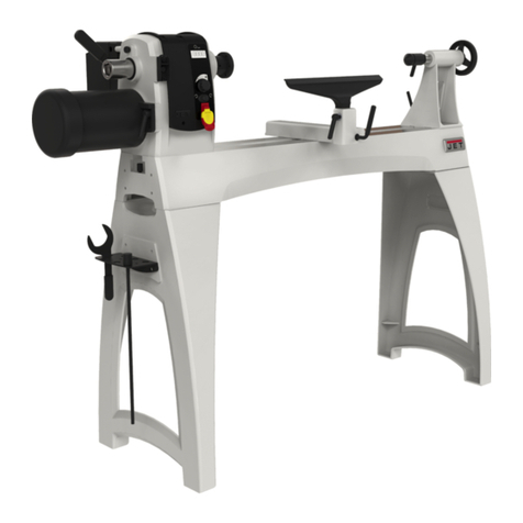
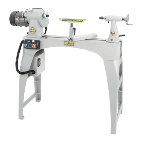
Record Power DML24X-MK2 User manual

Instruction
Manual
24” Beginners
Woodturning Lathe
DML24X-MK2
IMPORTANT
For your safety read
instructions carefully before
assembling this product.
Save this manual for
future reference.
Woodworking Machines & Accessories
Telephone: 0870 770 1777
Facsimile: 0870 770 1888
Email: sales@recordpower.co.uk
http://www.recordpower.co.uk

Dear Customer,
Thank you for investing in a RECORD POWER® WOODTURNING LATHE. Like all our products, it is made to the highest production
standards and is designed to give you years of satisfying service.
A complete list of accessories to enhance your enjoyment of woodturning is included at the back of this manual.
Please do not forget to fill in and return your guarantee card. (This does not affect your statutory rights).
PURPOSE OF THIS MANUAL
Please ensure you have sufficient basic skill before using this machine.
This manual serves to give details of Specification, Health & Safety, Installation & Assembly.
It does not serve to teach you the art and skill of Woodturning. This is best done by either attending a course run by a skilled
woodturner, obtaining one of the many publications on the subject or by viewing our website (www.recordpower.co.uk) where you can
find various woodturning tuition articles and projects.
RECORD POWER AND THE ENVIRONMENT
Considerations of environmental issues are an integral part of the design, production and other associated aspects of this product,
and all reasonable environmentally friendly options have been adopted throughout.
Users are advised to consider environmental issues associated with the use of this product, particularly when considering workpiece
material. Confirmation of sourcing from well-managed forests is advisable whenever practically possible.
This product is designed to have a long and useful life and to be passed down from generation to generation. However, should the
unlikely need arise to dispose of this lathe or any part thereof please recycle where facilities exist.
To assist you in the disposal of this product / component in an environmentally friendly way, below are listed the materials of the
product’s main components.
Headstock - Belt Guard - Motor & Spindle Pulleys
End Brackets - Tool Rest Base
Square/Plain/Angle Straps - Toolrest
Tailstock - Handwheel - Swivel Saddle
Main Spindle - Tailstock Barrel
Centre/2 spur centre - Toolrest stem
Bed Tubes
Motor - Motor Plate
Ratchet handles - Tailstock lock knob
Cable, wires
Switch assembly
Plug
Cast Iron
Cast Iron
Cast Iron
Cast Iron
Steel
Steel
Steel – Zinc Plated
Steel frame, copper windings, cast iron
Glass filled Nylon, Steel
Rubber, copper core
Various plastics, copper fittings
Various plastics, brass fittings

Contents
1. HEALTH & SAFETY GUIDANCE
2. ADDITIONAL SAFETY INSTRUCTIONS FOR LATHES
3. SPECIFICATION
4. ASSEMBLY INSTRUCTIONS
5. CONTROL IDENTIFICATION AND FUNCTION
6. PROCEDURE FOR CHANGING SPEED
7. PROCEDURE FOR CHANGING BELT
8. SPARE PART IDENTIFICATION
Record Power Guarantee
Terms and conditions
Record Power guarantees the mechanical parts of its machines against faulty construction for a period of 5 years from date of
purchase. The guarantee is limited to the obligation to repair or replace any parts which prove to be faulty.
All motors, electrics and electronic equipment have a guarantee period of 6 months.
It is understood that in all cases the guarantee does not entitle the customer to any refund for damages, interruption of work or any
indirect damage.
Parts will only be replaced if found faulty through a manufacturing defect.
The guarantee does not cover the replacement of worn consumable parts such as belts, bearings, cogs, wheels and blades which will
all need replacement over time dependent on use, loading and maintenance of the machine.
Please note the guarantee does not cover
• Accidental damage
• General wear and tear of mechanical parts
• Incorrect electrical connection
• Any unapproved machine modification
• Failure to follow manufacturers instructions
• If machine is used for any material other than that specified in the manufacturers handbook.
No claim for damage in transit will be entertained if goods are not signed for as damaged
Unless stated otherwise, the machines are not intended for continuous industrial use, doing so will invalidate the guarantee.
Claims for the recovery of carriage incurred returning the product, will only be entertained if the product has been demonstrated to fail
because of a manufacturing defect.
All guarantee claims should be made through the supplying dealer and must accompanied by proof of purchase.

READ ALL THE INSTRUCTIONS IN THIS MANUAL
CAREFULLY BEFORE ASSEMBLY, INSTALLATION AND USE
OF THIS PRODUCT.
KEEP THESE INSTRUCTIONS IN A SAFE PLACE FOR
FUTURE REFERENCE.
WARNING: When using electric tools, basic safety precautions
should always be followed to reduce the risk of fire, electric
shock and personal injury.
SAFE OPERATION
1. Eye Protection
The operation of any power tool can result in
foreign objects being thrown into your eyes, which can result in
severe eye damage. Always wear safety glasses or other
suitable eye protection. Wear safety glasses at all times.
Everyday glasses only have impact resistant lenses. They are
not safety glasses which give additional lateral protection.
2. Keep work area clear.
Cluttered areas and benches invite accidents and injuries.
3. Consider work area environment.
Do not expose the machine to rain or damp conditions.
• Keep the work area well lit.
• Do not use the machine in the presence of flammable
liquids or gases.
4. Guard against electric shock.
Avoid body contact with earthed or grounded surfaces.
5. Keep other persons away (and pets).
Do not let persons, especially children, not involved in the work,
touch the machine, or extension cord (if used) and keep visitors
away from the work area.
6. Store idle tools.
When not in use, tools should be stored in a dry locked- up
place, out of reach of children.
7. Do not force the machine.
It will do the job better and work more safely if operated at the
speed at which it was intended.
8. Use the right tool.
• Do not force small tools to do the job of a heavy-duty tool.
• Do not use tools for purposes not intended.
9. Dress properly.
• Non-slip footwear is recommended.
• Do not wear loose clothing, neckties or jewelry; they can be
caught in the moving parts.
• Roll up long sleeves above the elbow.
• Wear protective hair covering to contain long hair.
10. Use protective equipment
• Use safety glasses. (See note 1. above)
• Use face or dust shield if cutting operation creates dust.
11. Connect dust extraction equipment.
(See sectio 2. note 25)
12. Do not abuse the cord.
Never yank the cord to disconnect it from the socket. Keep the
cord away from heat, oil and sharp edges.
13. Secure work.
Ensure that your work piece is properly fixed before
commencing to cut.
14. Do not overreach.
Keep proper footing and balance at all times.
15. Maintain tools with care.
• Follow instructions for lubrication and changing accessories.
• Inspect electric cords periodically and, if damaged, have them
repaired by an authorized service facility.
• Inspect extension cords (if used) periodically and replace if
damaged. Always use proper size extension cord.
16. Disconnect Machine.
When not in use, before servicing etc, disconnect the machine
from the power supply.
17. Never leave machine running unattended.
Turn power off, do not leave machine until it comes to a
complete stop.
18. Remove adjusting keys and wrenches.
ENSURE chuck key is removed from chuck before switching the
machine ‘ON’, any adjusting wrenches should also be removed
from the machine.
19. Avoid unintentional starting.
- Ensure the switch is in the “OFF” position before turning on the
power from the main electricity supply.
20. Out-door Extension Leads.
Your lathe should not be used outdoors.
21. Stay alert.
Watch what you are doing, use common sense and do not use
the morticer when you are tired.
22. Check for damaged parts.
• Before use of the machine, it should be carefully checked to
determine that it will operate properly and perform its intended
function.
• Check for alignment of moving parts, binding of moving parts,
breakage of parts, mounting and any other conditions that may
affect its operation.
• A guard or other part that is damaged should be properly
repaired or replaced by an authorized service center unless
otherwise indicated in this instruction manual. -
Have defective switches replaced by an authorized service
centre.
• Do not use the machine if the switch does not turn on and off.
23. Warning!
• The use of any accessory or attachment, other than one
recommended in this instruction manual, or recommended by
our Company may present a risk of personal injury.
24. Have your machine repaired by a qualified person.
• This electric machine complies with the relevant safety rules.
Only qualified persons using original spare parts should carry
out repairs. Failure to do this may result in considerable danger
to the user.
Maintenance and Servicing
This machine requires very little maintenance. This handbook
gives clear instructions on installation, set up and operation.
Read these instructions carefully. Remember always to switch off
and unplug from the main electricity supply before carrying out
any setting up or maintenance operations.
Should you need advice on repair or maintenance on this
product, our Customer Service Department would be happy to
assist you.
1. Health & Safety Guidance

SAFETY IS A COMBINATION OF OPERATOR
COMMON SENSE AND ALERTNESS AT ALL
TIMES WHEN THE LATHE IS BEING USED.
WARNING: For your own safety, do not attempt to operate your
lathe until it is completely assembled and installed according to
the instructions.
SAFE OPERATION
1. Lathe and motor must be bolted down to a stand or
workbench for stability.
2. Before attaching workpiece to faceplate always “rough-out” to
as “true round” as possible. This will minimise vibration while
turning.
3. Always rough out “out of round” workpieces at slow speed.
Running lathe too fast could cause workpiece to be thrown from
lathe or turning tool to be jerked from your hands.
4. Always rotate workpiece by hand before starting the lathe. If
workpiece strikes tool rest, it could be split and thrown out of the
lathe.
5. Do Not allow turning tool to “bite” into workpiece, which could
result in splitting or ejection of workpiece from lathe. Always
position tool rest at the correct height such that the tool cutting
edge is on or above workpiece centre.
6. Do Not apply turning tool to workpiece below centreline of
lathe.
7. When using faceplate always ensure workpiece is well
secured.
8. Avoid awkward hand positions, where a sudden slip could
cause a hand to move into workpiece.
9. Remove all loose knots and bark before installing workpiece.
10. If turning tools are stored near lathe, hang them on wall
near tailstock end of lathe. Do not lay them on bench so that you
must reach over revolving workpiece to select them.
11. Keep firm hold and control of the turning tool at all times.
Use extreme caution when knots and voids are exposed. Turning
tool could be grab and be thrown, or dig into workpiece and
break it apart.
12. Find and read the WARNING label incorporated within the
Machine Label mounted on the lathe motor.
13. Finish all hand sanding BEFORE removing workpiece from
lathe. Do not exceed speed used for last cutting operation.
14. DO NOT remount faceplate turned workpiece to faceplate
unless you are deliberately turning eccentric work.
15. DO NOT remount between-centres turning if original centres
have been altered or removed, unless you are deliberately
turning eccentric work. Set to lowest speed when remounting a
between-centres turning.
16. Use extra caution when mounting a between-centres or
spindle turning to faceplate, or a faceplate turning to between-
centres, for subsequent operations. ENSURE lathe is set at
lowest speed before switching ON.
17. DO NOT mount a workpiece that contains excessive splits,
shakes, or loose knots to a faceplate or between centres.
18. DO NOT perform any operations when hand holding the
workpiece.
19. DO NOT mount a reamer, milling cutter, wire wheel, buffing
wheel, drill bit or any other tool to headstock spindle.
20. ALWAYS ensure that the turning tool is in contact with the
tool rest before commencing the cut.
21. When the tool rest base unit is not in use (as when sanding),
it should be moved away from the headstock, and the tool rest
removed.
22. It is normal for the motor to run hot. Therefore care should be
taken to avoid touching the motor, particularly when changing
speed.
23. Warning Labels – It is important that labels bearing Health &
Safety Warnings are not removed or painted over. New labels
are available from Customer Services.
24. Mechanical Safety – The security of all clamps, guards and
work holding devices should be checked before switching on.
25. Wood Dust – The fine particles of dust produced in sanding
operations can be a long-term health hazard if excessive. Some
woods do give off irritant dust that may cause a burning
sensation. We therefore strongly recommend the use of a dust
collector on your lathe and suitable dust mask / visor. Our
Customer Services will be happy to advise you on the correct
unit for your needs.
26. Machine falls under the scope of the ‘Health & Safety at
Work etc. Act 1974’, and the ‘Provision & Use of Work
Equipment Regulations 1998’. We recommend that you study
and follow these regulations. Further guidance can be found in
the Safe Use of Woodworking Machinery code of practice
booklet (L114) published by Health & Safety Executive.
For further help on any of the above matters please contact our
Customer Services Department at :-
Tel: 0870 770 1777 Fax: 0870 770 1888
WARNING: Do not allow familiarity (gained from frequent use of
your machine) to become commonplace. Always remember that
a careless fraction of a second is sufficient to inflict severe injury.
2. Additional Safety Instructions
For Woodturning Lathes

Max distance between centres 24” (610mm)
Max bowl Dia. over bed 9” (229mm)
Max spindle Dia. 6” (152mm)
Motor 230 V 50Hz 2.5A
Capacitor start & run drip proof type
Motor Power 430w (p1) 250w (p2)
Motor Speed 1425 min-1
Noise emission < 85dB(A)
Spindle Speeds 450, 950, 1500, 2000
Drive Poly V belt
Main Bearing Deep groove ball
Spindle Nose 3/4”ø whit. x 16tpi
Overall Dimensions
Length 51” (1295mm)
Depth 12” (305mm)
Height 113/4” (298mm)
Weight 40kg
3. Specification
4. Assembly Instructions
HEADSTOCK SPINDLE AND TAILSTOCK BARREL BORED TO SUIT NO.1 MORSE TAPER SHANK.
SPINDLE FLATTED TO SUIT 9/16" WHITWORTH. WRENCH TO FACILITATE FITTING AND RELEASE OF
SPINDLE NOSE ATTACHMENTS SUPPLIED.
Unpacking
NOTE: Make sure that all items are included by checking against
Parts Diagram / Parts List. Do not discard any packaging
material before carrying out this check.
WARNING: To avoid injury, do not attempt to run or use this
machine until all parts are fitted and working satisfactorily.
Installation
Before assembling and using your lathe, you must have a sturdy
bench or stand for it. Alternatively the Record Power® DML24S
Leg Set. If you wish to build your own bench, remember that the
lathe is heavy (see Specifications for correct weight). The bench
must not move during use.
WARNING
Inadequate strength of the bench could result in failure of the
bench and falling of the lathe. Serious injury could occur.
WARNING
The lathe must not shift or move. If there is movement when not
running, the movement will be exaggerated when turned on.
Serious injury could occur. To prevent movement, bolt the bench
to the floor and the lathe to the bench.
CAUTION
To avoid back injury, get help lifting the lathe. Bend your knees
lift with your legs not your back.
Wiring Instructions
The lathe supplied is fitted with a plug. The wires in the mains
lead are coloured in accordance with the following codes.
Green & Yellow: Earth Blue: Neutral Brown: Live
If a new plug is fitted
The green and yellow wire must be connected to the terminal
that is marked with the letter ‘E’ or by the earth symbol.
The blue wire must be connected to the terminal which is
marked with the letter ‘N’.
The brown wire must be connected the terminal which is marked
with the letter ‘L’
Machines for use in the UK are fitted with a BS1363 amp. 3 pin
plug. Replacement of the power cable should only be carried out
by a qualified electrician.
R.C.D (Residual Current Device)
For your additional safety, we always recommend the use of a
residual current breaker, or Earth leakage circuit breaker.

1. Bore 2 holes in the bench 13mm (1/2") dia., 86mm (3.3/8") from the front edge of the bench and 1067mm (42") apart (See Fig.1).
2. Position the two end brackets on the bench so that when
the long threaded bars are passed through the end brackets
they will pass through the corresponding holes in the bench.
3. Place the bed tubes in position butting up to the stop faces
on the end brackets.
4. Place each angle strap in position over each end bracket. It
should be noted that where the angle strap contacts the bed
tube the angle strap has a convex curve giving a single contact
on one of the bed tubes, and a concave curve giving two
contacts on the other bed tube. The angle strap placed at the
right hand end of the bed should have the single contact on the
front bed tube, and the angle strap placed at the left hand end of
the bed should have the double contact on the front tube.
5. Ensure that the two pairs of contact points between the left
hand bracket and the back bed tube, also the right hand bracket
and the front bed tube are in full contact, then bolt the angle
straps, bed tubes and end brackets down to the bench using the
long threaded bars, nuts and washers provided.
6. Mount the headstock on to the bed tubes.
7. Note that the square straps have single and double contact
points with the bed tubes. Thread the bolt through a square
strap and up through the hole in the headstock arranging for the
two contact points of the square strap to clamp on to the front
bed tube, and the single contact point to clamp on to the back
bed tube. Assemble the washer and nut to the headstock bolt
and tighten.
8. Remove the ratchet handle and washer from the stud on the
side of the headstock, and open the belt guard. Feed the motor
into the headstock, locating the motor pivot pin in the recess and
the stud in the slot in the motor plate. Replace the ratchet handle
and washer on the stud, position the belt over the appropriate
pulleys (see speed chart section 6), and apply slight downward
pressure on the motor to obtain correct belt tension, then tighten
the handle.
9. Mount the tailstock on to the bed tubes.
10. Thread the tailstock bolt through a square strap and up
through the hole in the headstock. Arrange for the two contact
points of the square strap to clamp on to the front bed tube, and
the single contact point to clamp on the back bed tube.
Assemble the washer and nut on to the tailstock bolt and tighten.
11. Mount the banjo on to the bed tubes.
Fig. 1
Lathe Position
End bracket
for headstock
Single pad nearest to front of
bench (tailstock end only)
Drill 2 holes 13mm
Dia. in bench top
for 12mm Dia.
threaded bar
Front of bench
12. Thread the banjo bolt through a square strap and up through
the slot in the banjo. Assemble the washer and nut on to the bolt
and tighten.
13. Fit the tool rest into the banjo and tighten the handle.
14. Fit the 2-spur centre into the main spindle, and the 90º back
centre into the tailstock barrel.
15. Ensure that the grub screws in the two belt pulleys are fully
tightened (two grub screws in each tapped hole). It is advisable
that these should be checked periodically, use a 3mm hexagonal
wrench.
Adjustments
16. Adjustment of the tailstock along the bed tubes is obtained
by slackening the nut in the cavity in the back of the tailstock
with a wrench, and sliding the tailstock to the desired position,
then lock firmly in position. When working between centres, the
tailstock centre is positioned in the workpiece by means of the
tailstock hand wheel, the barrel is then locked in position by
means of a plastic knob on the back of the tailstock.
17. Adjustment of the banjo on the bed tubes is obtained by
slackening the nut above the slot in the banjo and moving the
banjo to the desired position, (it will move more freely if the bolt
is pushed up from below), then locking firmly.
Ensure that the banjo base overlaps outside the centre lines of
the bed tubes.
18. Adjustment of the tool rest is obtained by slackening the
ratchet handle in the near side of the banjo and moving the tool
rest to the desired position, then locking firmly.
19. Always ensure that the above mentioned adjustments have
been followed by firm clamping before starting the machine, and
always turn the workpiece by hand to ensure it will not foul any
part of the machine.
20. If the lathe is on a bench that is warped or uneven, the effect
will be to throw the headstock and tailstock centres into
misalignment. Correct by placing a spirit level across the bed
tubes, firstly at headstock end, then at tailstock end to determine
the degree of correction required. Place packing strips either
under the front of one of the end brackets or the back,
depending on the direction of correction required to give identical
spirit level readings at both ends of the bed. When both readings
are identical, the centres will be aligned.

5. Control Identification & Function
CONTROL FUNCTION OPERATION / COMMENT
ON / OFF Switch Starts and Stops Motor. No Volt Release switch Green (1) START, Red (0) STOP. If
power supply is interrupted during operation lathe will not
restart until START button is pressed.
Tool rest Supports turning tool Position as per lathe safety instructions (section 2, part 5)
2 Prong drive Holds and drives workpiece for spindle turning Provides driving force from motor. Firm contact required.
90º Back centre Supports free end for spindle turning Provides support for end of spindle which is not driven.
Headstock lock Locks headstock to bed tubes. Lock from inside headstock using a 19mm (3/4”) wrench. Turn
clockwise to lock . Locate and lock firmly before mounting
workpiece.
Toolrest lock Locks toolrest post into base Turn clockwise to lock.
Toolrest base lock Locks toolrest base to bed tubes Turn clockwise to lock
Tailstock lock Locks tailstock to bed tubes Turn right to lock. Position tailstock along bed tubes before
locking
Motor plate clamp Locks motor when belt is tight. Loosen to adjust belt for selected speeds. Tighten when belt is
properly positioned.
Tailstock handwheel Moves 90º back centre into workpiece Rotate clockwise to move 90º back centre towards workpiece.
Tailstock centre lock Locks 90º back centre Turn clockwise to lock after positioning 90º back centre with
handwheel.

6. Procedure For Changing Speed
7. Procedure For Changing Belt
1. Switch off and disconnect plug from power supply.
2. Open the guard.
3. Release the motor plate ratchet handle.
4. It is important to handle the motor pulley to release the belt
tension since the motor casing may become very hot.
When moving between middle and low speed, use your left hand
to pull the motor pulley towards you and move the belt to the
appropriate position with the right hand.
When moving between middle and high speed, use your right
hand to pull the motor pulley towards you and move the belt with
the left hand.
5. Allow the motor to fall back into position.
6. Turn the main spindle by hand to ensure the proper bedding
of the belt.
7. Apply slight downward pressure to the motor pulley, and
tighten the motor plate ratchet handle.
8. Close and secure the guard.
WARNING
It is normal for the motor to run hot, therefore care should be taken to
avoid touching the motor particularly when changing speed.
WARNING
Ensure belt guard is in place and locked before using lathe. Loose
items, clothing or hands may enter opening and become entangled in rotating parts. Serious injury could occur.
Speed Chart
Speed Motor Main Spindle
min-1 (RPM) Pulley Pulley
450 4 8
950 3 7
1500 2 6
2000 1 5
4321
8765
MOTOR SPINDLE
MAIN SPINDLE
1. Switch off and disconnect plug from power supply.
2. Ensure that the thread protector is on the spindle nose.
3. Open the belt guard.
4. Remove the locking grub screw from the spindle pulley.
Unscrew the bottom grub screw a few turns so that the pulley
will slide freely along the full length of the spindle.
5. Remove the socket head cap screw and washer from the left
hand end of the spindle.
6. Obtain a piece of brass or similar material softer than mild
steel, of a diameter between 11mm (7/16") and 13mm (1/2"),
place at the left hand end of the spindle and carefully tap with a
hammer, driving the spindle through to the right until it becomes
sufficiently free to allow the belt to be changed.
7. Change the belt.
8. If the large bearing is still in the headstock then the spindle
should be tapped back in position using a piece of wood
between the hammer and the thread protector. If the large
bearing has come out with the spindle, then it should be
replaced by tapping the outer ring only, tapping round the ring to
ensure it seats squarely. If the small bearing has been pushed
out by the previous operation, then this also should be tapped
back on the outer ring only.
9. Replace the socket head cap screw and washer (do not over
tighten).
10. Position the spindle pulley so as to line up with the motor
pulley. Tighten the spindle pulley bottom grub screw, ensuring
that it locates on the spindle flat, then replace the locking grub
screw.
11. With the belt in position and the guard closed, the machine
should be run for a short time to enable the belt to bed in.

8. Spare Part Identification

1 ZBD End bracket 2
2 ZBH Angle strap 2
3 ZAES Washer – M12 large 2
4 CKSM Spindle pulley – 4 speed 1
5 CKMM Motor pulley – 4 speed 1
6 ZBQ Main spindle 1
7 ZCP Thread protector 1
8 ZBW Toolrest stem 1
9 ZPN 90º Back centre 1
10 ZBR Tailstock barrel 1
11 BOPM Motor, Motor Plate, 1
Switch, Cable & Plug (U.K.)
For replacement for other than U.K. please specify
12 ZBA Handwheel 1
13 ZBB Headstock 1
14 ZBC Tailstock 1
15 ZBE Tool rest base 1
17 ZBJ Belt guard 1
18 ZBT Square strap 1
19 ZCF 10” Toolrest 1
20 ZPI 5/8” 2 Prong centre 1
21 ZBP Bed tube 2
22 ZABD Bearing – 6202ZZ 1
23 ZABE Bearing – 6204ZZ 1
24 ZBS Motor plate pivot 1
25 ZCA Pry bar # 1
Item Part Description Qty
No. No.
Item Part Description Qty
No. No.
26 ZBO Poly V-belt, 4 rib 1
27 CLKB M6 Dog point knob 1
28 ZABG M12 x 90mm High tensile hex. bolt 1
29 CLRC M8 Ratchet handle - Toolrest 1
30 ZABI M10 x 35mm Threaded bar 1
31 ZABK M6 x 18mm Socket head cap screw 6
32 ZABL M6 x 8mm Socket grub screw 3
33 ZABM Nut – M12 5
34 CLRG M10 Ratchet handle 1
35 ZABO Washer – M12 7
36 ZABP Washer – M10 1
37 ZABR M6 x 10mm dog point grub screw 1
38 ZABS Bellville washer 1
39 ZABT M6 x 20mm Sellock pin 3
40 BOAF M12 x 210mm Threaded bar 2
41 ZAEW Washer – M6 4
42 ZACJ 3mm Hexagonal wrench # 1
43 ZADA 5mm Hexagonal wrench # 1
44 CKPS Plain strap 2
45 CKRH M12 Ratchet handle 2
46 CKCB M12 x 80mm Cup Square 1
# Denotes not illustrated in parts diagram

EU Declaration of Conformity
Cert No: EU / ALL LATHES / 6
RECORD POWER LIMITED, at Unit B, Adelphi Way, Ireland Industrial Estate, Staveley S43 3LS
declares that the machinery described:-
1. Type: Woodworking Lathe
2. Model No: DML24X-MK2
3. Serial No .........................................................................
Conforms with the following directives:-
MACHINERY DIRECTIVE 98/37/EC
(repealing / replacing Directives 89/392/EEC
91/368/EEC
93/44/EEC
93/68/EEC)
LOW VOLTAGE DIRECTIVE 73/23/EEC
and its subsequent amendment 93/68/EEC
ELECTRO-MAGNETIC 89/336EEC
COMPATIBILITY DIRECTIVE 92/31EEC
and its subsequent amendments 93/68EEC
and complies with the relevant essential health and safety requirements.
Signed................................................Dated: 20/10/03
Andrew Greensted
Managing Director
Table of contents
Other Record Power Lathe manuals

Record Power
Record Power cl3b User manual

Record Power
Record Power DML305 User guide

Record Power
Record Power DML320 User guide

Record Power
Record Power CL3-CAM User guide

Record Power
Record Power MAXI-1 User guide

Record Power
Record Power DML36SH-CAM User guide

Record Power
Record Power DML250 User manual

Record Power
Record Power DML320-EP User guide

Record Power
Record Power DML305-VS User manual

Record Power
Record Power Coronet Series User guide