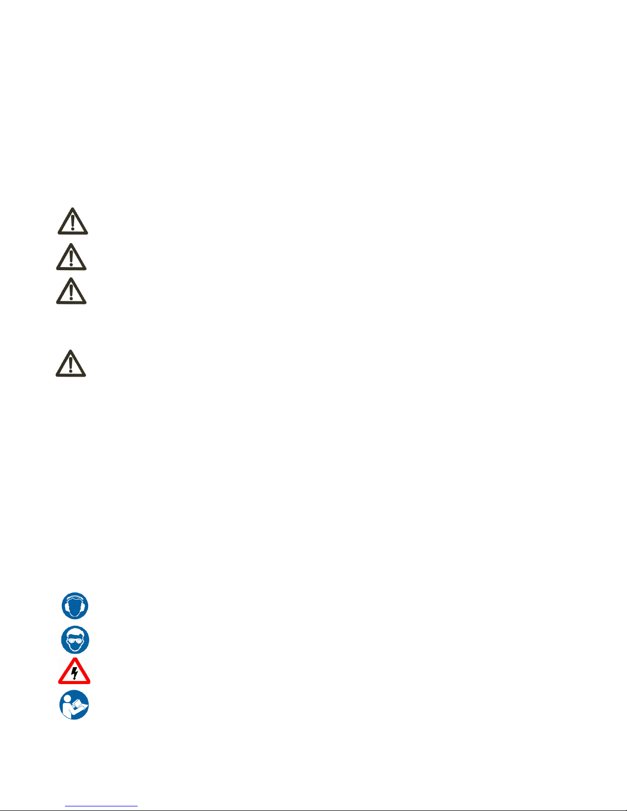
WoodFast BS230A User manual

Instruction
Manual
IMPORTANT
For your safety, read
instructions carefully
before assembling or
using this product.
Save this manual for
future reference. Original Instruction
V. 1-201810
/RIGINAL¬)NSTRUCTION¬-ANUAL
6ERSION¬
&EBRUARY¬
7OODWORKING¬-ACHINES¬¬!CCESSORIES
4ELEPHONE¬¬¬
&AX¬¬¬
3TARTRITE
5NIT¬"¬!DELPHI¬7AY
3TAVELEY¬¬3¬,3
%MAIL¬SALES RECORDPOWERCOUK
WWWSTARTRITECOUK
%¬%¬¬%¬¬¬
)NDUSTRIAL¬¬
"ANDSAW
)-0/24!.4
&OR¬YOUR¬SAFETY¬READ¬INSTRUCTIONS¬CAREFULLY¬BEFORE¬
ASSEMBLING¬OR¬USING¬THIS¬PRODUCT¬3AVE¬THIS¬
MANUAL¬FOR¬FUTURE¬REFERENCE
(%!,4(¬!.$¬3!&%49¬'5)$%,).%3
!LWAYS¬FOLLOW¬THE¬INSTRUCTIONS¬PROVIDED¬WITH¬THE¬MANUAL¬!LWAYS¬WEAR¬SAFETY¬GLASSES¬WHEN¬USING¬WOODWORKING¬
EQUIPMENT¬!LWAYS¬DISCONNECT¬THE¬POWER¬BEFORE¬ADJUSTING¬ANY¬EQUIPMENT¬&AILURE¬TO¬OBSERVE¬PROPER¬SAFETY¬
PROCEDURES¬AND¬GUIDELINES¬CAN¬RESULT¬IN¬SERIOUS¬INJURY
7!2.).'¬$O¬NOT¬ALLOW¬FAMILIARITY¬GAINED¬FROM¬FREQUENT¬USE¬OF¬YOUR¬MACHINE¬AND¬ACCESSORIES¬TO¬BECOME¬
COMMONPLACE¬!LWAYS¬REMEMBER¬THAT¬A¬CARELESS¬FRACTION¬OF¬A¬SECOND¬IS¬SUFlCIENT¬TO¬INmICT¬SEVERE¬INJURY !LWAYS¬WEAR¬SAFETY¬GLASSES¬WHEN¬
USING¬WOODWORKING¬EQUIPMENT
!LWAYS¬READ¬THE¬INSTRUCTIONS¬
PROVIDED¬BEFORE¬USING¬
WOODWORKING¬EQUIPMENT
9” BANDSAW
BS230A

-2-
INDEX
1 GENERAL INFORMATION
2 SAFETY PRECAUTIONS
3 SPECIFICATIONS
4 ASSEMBLY
5 ADJUSTMENTS
6 ADJUSTMENTS & OPERATION
7 MAINTENANCE &TROUBLE SHOOTING
8 DIAGRAMS AND COMPONENTS

-3-
1. GENERAL INFORMATION
1.1 FOREWORD
Some information and illustrations in this manual may differ from the machine in your hand, since all the configurations
inherent in the machine complete with all the optional are described and illustrated. Therefore, refer only to that
information strictly related with the machine configuration you have purchased.
With this manual we would like to provide the necessary information for maintenance and proper use of the machine.
The distribution network is at your service for any technical problem, spare parts or any new requirement you many
have for the development of your activity.
This manual must be read and understood before operating the machine. This will provide a better
working knowledge of the machine, for increased safety and to obtain the best results.
To better stress the importance of some basic passages, they have been marked by some preceding.
symbols:
1.2 MACHINE IDENTIFICATION
There is a identification plate fixed to the machine, containing the manufacturer’s data, year of construction, serial
number and technical specifications.
1.3 CUSTOMER SERVICE RECOMMENDATIONS
Apply the machine to skilled and authorized technical staff to carry out any operation dealing with parts disassembly.
Keep to the instructions contained in this manual for the correct use of the machine.
Only skilled and authorized staff shall use and service the machine after reading this manual.
Respect the accident prevention regulations and the general safety and industrial medicine rules.
Indicates imminent risks which may cause serious injury to the operator or other persons. Be
careful and scrupulously follow the instructions.
A statement advising of the need to take care lest serious consequences result in harm to
material items such as the asset or the product.
CAUTION
WARNING
CAUTION
2. SAFETY PRECAUTIONS
2.1 SAFETY REGULATIONS
The manufacturer disclaims all responsibilities for damages to persons or things, which might be caused by any failure
to comply with the safety regulations.
- KNOW YOUR TOOL
Read and understand the owners manual and labels affixed to the tool. Learn its application and limitations as well as its
specific potential hazards.
- GROUND THE TOOL.
This tool is equipped with an approved 3-conductor cord and a 3-prong grounding type plug to fit the proper grounding
type receptacle. The green conductor in the cord is the grounding wire. NEVER connect the green wire to a live terminal.
- KEEP GUARDS IN PLACE.
Keep in good working order, properly adjusted and aligned.
- REMOVE ADJUSTING KEYS AND WRENCHES. Form habit of checking to see that keys and adjusting wrenches are
removed from tool before turning it on.
WARNING Read carefully the operation and maintenance manual before starting, using, servicing and
carrying out any other operation on the machine.

-4-
- KEEP WORK AREA CLEAN.
Cluttered areas and benches invite accidents. Make sure the floor is clean and not slippery due to wax and sawdust
build-up.
- AVOID DANGEROUS ENVIRONMENT.
Don’t use power tools in damp or wet locations or expose them to rain. Keep work area well lit and provide adequate
surrounding work space.
- KEEP CHILDREN AWAY.
All visitors should be kept a safe distance from work area.
- MAKE WORKSHOP CHILD-PROOF.
with padlocks, master switches or by removing starter keys.
- USE PROPER SPEED.
A tool will do a better and safer job when operated at the proper speed.
- USE RIGHT TOOL.
Don’t force the tool or the attachment to do a job for which it was not designed.
- WEAR PROPER APPAREL.
Do not wear loose clothing, gloves, neckties or jewelry (rings, watch) because they could get caught in moving parts.
Non-slip footwear is recommended. Wear protective hair covering to contain long hair. Roll up long sleeves above the
elbows.
- ALWAYS WEAR SAFETY GLASSES.
Always wear safety glasses (ANSI Z87.1). Everyday eye-glasses only have impact resistant lenses, thet are NOT safety
glasses. Also use a face or dust mask if cutting operation is dusty.
- DON’T OVERREACH.
Keep proper footing and balance at all times.
- MAINTAIN TOOL WITH CARE.
Keep tools sharp and clean for best and safest performance. Follow instructions for lubricating and changing
accessories.
- DISCONNECT TOOLS.
Before servicing, when changing accessories or attachments.
- AVOID ACCIDENTAL STARTING.
Make sure the swich is in the ‘’OFF’’ position before plugging in.
- USE RECOMMENDED ACCESSORIES.
Consult the manual for recommended accessories. Follow the instructions that accompany the accessories. The use of
improper accessories may cause hazards.
- NEVER STAND ON TOOL.
Serious injury could occur if the tool tips over. Do not store materials such that it is necessary to stand on the tool to
reach them.
- CHECK DAMAGED PARTS.
Before further use of the tool, a guard or other parts that are damaged should be carefully checked to ensure that
they will operate properly and perform their intended function. Check for alignment of moving parts, breakage of parts,
mounting, and any other conditions that may affect its operation. A guard or other parts that are damaged should be
properly repaired or replaced.
- NEVER LEAVE MACHINE RUNNING UNATTENDED.
Turn power ‘’OFF’’. Don’t leave any tool running until it comes to a complete stop.
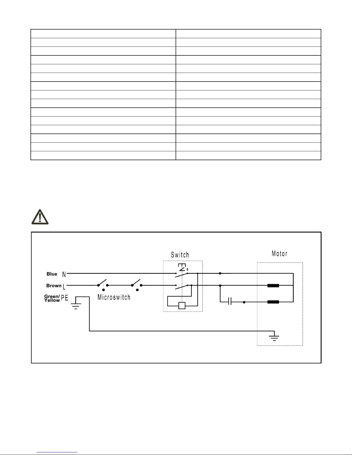
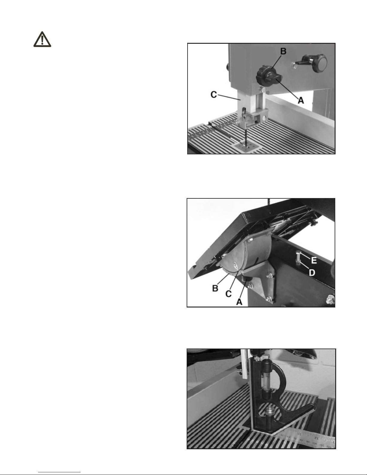
- Adjust the upper guide to just clear workpiece.
- Make sure that the blade is properly adjusted and tensioned before operating.
- Do not remove small jammed pieces until the blade has completely stopped.
- Hold workpiece firmly against the table. Do not saw a workpiece which does not have a flat surface unless it can be
supported.
- Turn the machine off if the workpiece is to be backed out of an uncompleted cut.
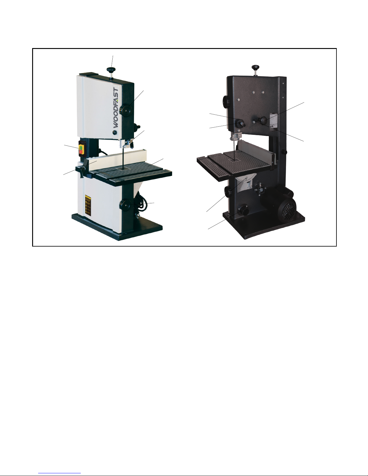
- To reduce the risk of injury from accidental starting, turn the switch off, unplug the bandsaw and remove the switch key
before changing the set-up, removing covers, guards or the blade.
- Check the alignment of moving parts, binding of moving parts, breakage of parts, bandsaw stability and any other
conditions that may affect the way the bandsaw works.
- If any part is missing, bent or broken in any way, or if any electrical parts do not work properly, turn the bandsaw off
and unplug the saw. Replace damaged or missing parts before using the bandsaw again.
- Choose the right blade size, style and cutting speed for the material and the type of cutting you plan to do.
- Make sure the blade teeth point downward, towards the table.
- Make sure the blade guides and thrust bearings are properly adjusted.
- Make sure the blade tension is properly adjusted.
- To reduce the risk of accidental blade contact, minimize blade breakage and provide maximum blade support, always
adjust the upper blade guide and blade guard to just clear the workpiece.
- Caution: Never cut metals with this bandsaw, only wood and wood products. Use extra caution with large, very small
or awkward workpieces.

-5-
- Use extra supports (tables, blocks, etc...) for any workpieces large enough to tip when not held down to the table top.
- NEVER use another person as a substitute for a table extension, or as additional support for a workpiece that is longer or wider than
the basic bandsaw table, or to help feed, support or pull the workpiece.
- When cutting irregularly shaped workpieces, plan your work so it will not slip and pinch the blade. A piece of molding for example,
must lie flat or be held by a fixture or jig that will not let it twist, rock or slip while being cut.
- Properly support round material such as dowel rods or tubing. They have a tendency to roll during a cut, causing the blade to “bite”.
To avoid this, always use a “V” block or clamp the work to the miter guage.
- Cut only one workpiece at a time.
Before starting your cut, watch the saw while it runs. If it makes an unfamiliar noise or vibrates a lot, stop immediately. Turn the saw
off and unplug. Do not restart until you have found and corrected the problem.
- Keep all visitors at a safe distance from the bandsaw.
- Make sure bystanders are clear of the table and the workpiece.
- Let the blade reach full speed before cutting.
- It will do the job better and safer at its designed rate.
- Feed the workpiece into the blade only fast enough to let the blade cut without bogging down or binding.
WARNING Accident caused by unqualified electrical element which connect machine and unconventional
installation, manufacturer assumes no responsibility.
WARNING Accident cause by change machine function or change spare part arbitrarily, manufacturer
assumes no responsibility.
Accident caused by operation under missing part or damage condition,manufacturer assumes no
responsibility
WARNING
2.2 RESIDUAL RISKS
- contact with tool
- contact with moving parts (belts, pulleys, etc..)
- recoil of the piece or part of it
- accidents due to wood splinters or fragments
- tool insert ejection
- electrocution from contact with live parts
- danger due to incorrect tool installation
- inverse tool rotation due to incorrect electrical connection
- danger due to dust inhalation in case of working without vacuum cleaner.
2.3 SAFETY AND INFORMATION SIGNALS
This signals may be applied on the machine; in some cases they indicate possible danger conditions, in others they
serve as indication.
Always take the utmost care.
SAFETY SIGNALS:
Wear hearing protection systems.
Risk of eye injury. Wear eye protection.
Danger of electric shock. Do not access the area when the machine is powered.
Carefully read and understand the manual before using the machine.
INFORMATION SIGNALS:
Indicate the technical characteristics, direction of rotation and inclination, block and release, etc.
Carefully following the directions to simply the use and adjustment of the machine.
The signals are graphically described and do not require further explanation.
Despite observance of all the safety regulations, and use according to the rules described in this
manual, residual risks may still be present, among which the most recurring are:
WARNING

3. SPECIFICATIONS
3.1 MAIN COMPONENTS
1. Tension adjustment knob. This feature controls the amount of blade tension. Proper blade tension is important to make
accurate cuts.
2. Upper hinged door lock knob. Gain access to blade.
3. Upper blade guide assembly . The blade guides support the blade and prevent it from twisting during operation. An
adjustment is necessary when the blade is changed or replaced.
4. Tilting table.
5. Lower hinged door lock knob. Gain access to blade.
6. Main On/Off switch.
7. Rip fence. Use as a support guide for ripping operations.
8. Dust port. This feature helps eliminate sawdust from inside the machine. A 1-1/4” vacuum hose or dust collector
adaptor can be used for optimal sawdust removal.
9. Bevel scale pointer. The bevel scale shows the degree to which the table is tilted for bevel cutting.
10. Upper blade guide lock knob. Loosen this knob before adjusting blade guide height.
11. Upper blade guide adjust wheel. The upper blade guide assembly should be lowered to just above the workpiece
while cutting. Always adjust and then lock it by tightening the upper blade guide lock knob before turning on the bandsaw.
12. Blade tracking lock knob. Locks the blade tracking adjustment.
13. Blade tracking adjust handle. This adjust handle should be adjusted to maintain proper blade tracking and locked
using the blade tracking lock knob.
-6-
1
2
3
4
5
6
7
8
9
10
11
12
13

3.2 TECHNICAL SPECIFICATION
SPECIFICATION BS230A
Blade length 1511mm
Blade widthr 3-6.5mm
Blade speed 800m/min
Maximum cutting height 90mm
Cutting Throat 220mm
Table Size 300x300mm
Table Tilt 0-45°
Floor to Table Height 305mm
Bandwheel Dia. 225mm
Motor Power 1/3HP
Volt 220-240V/50Hz
Extractor Port Dia. 39
Net/Gross Weight 17/19Kgs
Package Siae 795x335x420mm
To avoid electrocution or fire, any maintenance or repair to electrical system should be done only
by qualified electricians using genuine replacement parts.
WARNING
3.3 ELECTRICAL CONNECTION
- Electrical installation should be carried out by competent, qualified personnel.
- The mains connection should be made using the terminal box.
- Replacement of the power supply cable should only be done by a qualified electrician.
-7-
Brown
Blue
Green/
Yellow

-8-
3.4 NOISE LEVEL
No load Load
Sound Pressure Level < 80dB(A) < 90dB(A)
Sound Power Level < 90dB(A) < 100dB(A)
The noise levels measured are emission levels and not necessarily the safe working level. Although there is a
correlation between the emission levels and the exposure levels, this cannot be used reliably to determine whether or
not further precautions are required. The factors which affect the actual level of operator exposure include the duration
of exposure, the ambient characteristics and other sources of emission, for example, the number of machines and
other adjacent machining. The permitted exposure values may also vary from country to country. Nevertheless, this
information allows the user of the machine to better evaluate the dangers and risks.
Other factors which reduce exposure to noise are:
- correct tool choice
- tool and machine maintenance
- use of hearing protection systems (e.g. headsets, earplugs,...)
WARNING Please use the hearing protection systems if the above mentioned noise levels exceed 95dB(A).
3.5 DUST EXTRACTION
If this band saw is operated indoors it is recommended to have it connected to a dust collector. The suction connector,
supplied with the machine, has to be fitted to the dust ejection port of the saw for this purpose. The diameter of the
suction connector is 1-1/4”.
- Workmen working in operations processing oak or beech timber where found to develop more often cancer of the
mucous membrane of the nose (adenocarciome of the inner nose) then other workers.
- Experience shows that skin contact with oak or beech dust does not cause cancer
Wood dust and chips, together with an ignition source and the oxygen in the ambient air, can
cause fires and explosions, injuries and allergies.
WARNING

-9-
4.1 INSTALLING THE TABLE
- Remove the carriage bolt and plastic nut from the table (see
B & C Fig.4.1.2 as reference) to allow the blade to slide into the
table slot. Slide the blade through the slot in the table and then
place the table (A) Fig.4.1.1 onto the bandsaw trunnion (B).
- Align the four mounting holes of the table with the ones in the
trunnion.
- Fasten the table to the trunnion using four hex. bolts and tooth
washers (C) Fig.4.1.1.
- Place the table insert (A) Fig.4.1.2 in the opening in the table.
Install the carriage bolt (B) and plastic nut (C) to the table and
tighten.
4. ASSEMBLY
4.2 INSTALLING RIP FENCE AND MITER
GAUGE ON TABLE (IF NEEDED)
The rip fence (A) Fig.4.2 is used as a fence to guide the
workpiece for ripping operations and the miter gauge (B) is used
for angled miter cuts and also to push the workpiece into the
blade.
- Slide rip fence (A) Fig.6 onto the table and secure it by
pushing down on the lock handle (C). It may be necessary to
rotate the lock handle counterclockwise to allow the rip fence to
fit onto the table. Rotate locking handle clockwise before locking
the handle in position.
- Place the miter gauge (B) Fig.4.2 into the miter gauge slot (D)
in the table on the right side of the blade.
FIG.4.1.1
FIG.4.1.2
4.3 MOUNTING YOUR BANDSAW
If your bandsaw is to be used in a permanent location, it
should be clamped securely to a firm supporting surface
such as a workbench or board. If using a board, it should
be large enough to avoid tipping of the saw during
operation. Any good quality plywood or chipboard with
a minimum thickness of 3/4” is recommended. (Thinner
chipboard can break). Use 2 or more “C” clamps to
securely clamp the base of the bandsaw to the board.
FIG.4.2
To avoid injury, if any parts are missing, do not attempt to assemble the bandsaw, plug in the
power cord, or turn the switch on, until the missing parts are obtained and installed correctly.
WARNING
For your own safety, never connect plug to power source outlet, or insert switch key until all
assembly steps are complete and until you have read and understood the entire instruction
manual.
WARNING

5. ADJUSTMENTS
-10-
WARNING Turn off the saw, remove the main On/Off switch safety key and unplug the power cord before
making any adjustments on the saw.
5.1 ADJUSTING POSITION OF THE THE
UPPER BLADE GUIDE ASSEMBLY
The upper blade guide assembly (C) Fig.5.1 should
always be set about 1/8” above or as close as possible to
the top of the surface of the workpiece being cut.
- Loosen the upper blade guide assembly lock knob (A)
Fig.5.1.
- Turn the upper blade guide assembly adjusting knob (B)
to position the blade guide assembly (C) 1/8” above the
surface of the workpiece.
- Tighten the upper blade guide assembly lock knob
clockwise to secure the adjusting knob.
FIG.5.2
FIG.5.3
5.2 ADJUSTING THE TABLE
- Loosen the table lock knob (A) Fig.5.2.
- Tilt the table to the desired angle using the bevel angle
scale (B) Fig.8 and pointer (C) as a guide.
- Retighten the table lock knob by turning it clockwise to
secure the table angle.
5.3 SETTING TABLE SQUARE TO THE
BLADE
- Loosen the upper blade guide assembly lock knob (A)
Fig.5.1 and position the upper blade guide assembly all
the way up. Retighten the lock knob.
- Loosen the table lock knob (A) Fig.5.2.
- Place a small square on the table against the flat side of
the blade or as close as possible as shown in Fig.5.3.
- Set the table to a perfect 900 angle to the blade and
lock the table using the table lock knob. Loosen hex. nut
(D) Fig.5.2 under the table and turn the table 00 positive
stop bolt(E)until it touches the table. Retighten the hex.
nut after the adjustment is done.
- Check the blade squareness to the table. Readjust if
necessary.
- Adjust the pointer (C) using a #2 Phillips screwdriver,
position pointer at the 00, retighten pointer screw.
FIG.5.1

WARNING
WARNING
-11-
5.5 TENSIONING THE BLADE
Turn the blade tension adjusting knob (A) Fig.5.4 clockwise
until the blade is tensioned. The blade tension can be checked
by pushing on the blade midway between the two wheels.
The blade should move slightly with firm finger pressure. It is
recommended that the blade movement be only 1/8”.
5.6 TRACKING THE BLADE
The blade tension must be properly adjusted before tracking the
blade.
- Slowly turn the upper wheel clockwise by hand while watching
the blade on the tire. If the blade moves away from the centre of
the tire, the tracking will need to be adjusted.
- Loosen blade tracking lock knob (A) Fig.5.6 located at the rear
of the bandsaw behind the upper wheel.
FIG.5.4
FIG.5.6
5.4 CHANGING /INSTALLING THE BLADE
Wear safety glasses to avoid being scraped if the blade should
suddenly uncoil. Wearing gloves, carefully uncoil new blade by
holding it at arms length.
- Loosen the upper blade guide assembly lock knob and position
the guide assembly about half way between the table and the
frame. Retighten the lock knob.
- Open the front covers by turning the cover lock knobs
counterclockwise.
- Remove the table carriage bolt, plastic nut and table insert.
Replace these parts after the blade has been installed.
- Loosen the blade tension adjusting knob (A) Fig.5.3
(counterclockwise).
- Slide the old blade off the wheels and out from the protective
guards.
- Slide the new blade into the slot of the table with the teeth
facing forward and down toward the table.
- Slide blade behind the protective guards and place the blade
on both wheels. Centre the blade on the rubber tires.
Be careful not to overtension or undertension the blade.
Overtensioning may cause the blade to break while
undertensioning may cause the blade to slip off the wheels.
Proper blade tension is necessary for accurate cutting.
- If the blade moved toward the front of the saw, turn the adjustment handle (B) clockwise while turning the wheel by hand until the
blade rides in the centre of the tire. If the blade moved away the front of the saw, turn the adjustment handle counterclockwise while
turning the wheel by hand until the blade rides in the centre of the tire.
- Check the position of the blade on the lower wheel. The blade should be completely on the tire. If not, adjust the tracking until the
blade is on both tires.
- Rotate the upper wheel by hand in a clockwise direction a few more times. Make sure the blade remains in the same location on the
tires. Readjust if necessary until the blade tracks properly.

5.7 ADJUSTING UPPER AND LOWER BLADE GUIDES AND BACK-UP BEARINGS
WARNING
WARNING
WARNING
The upper and lower blade guides and back-up bearings support the bandsaw blade during cutting
operations. The adjustment of the guides and bearings should be checked whenever a different blade is
installed.
Allowing the blade teeth to hit the blade guides while the saw is in use will ruin the blade and may
damage the sharpened edge of the teeth. Proper adjustment of the upper and lower blade guide
assemblies will help prevent this from occurring.
The back-up bearing is intended to support the back edge of the blade while cutting. The blade should not
contact the bearings when cutting is stopped.
- Adjust the position of the upper blade guide support (A)
Fig.5.7.1first. Loosen set screw (B) using a hex. key.
- Slide the blade guide support until the front edge of the blade
guides (A) Fig.5.7.2 are about 1/32” behind the gullet of the
blade (behind the blade teeth). Tighten the set screw.
- Repeat for the lower blade guide support. Adjust the position
of the lower blade guide support (A) Fig.5.7.3. Loosen hex. nut
and bolt (B).
- Slide the blade guide support until the front edge of the blade
guides (C) Fig.5.7.3 are about 1/32” behind the gullet of the
blade (behind the blade teeth). Tighten the hex. nut and bolt.
- Adjust the upper blade guide pins (A) Fig.5.7.2. Loosen
the two set screws (B) and press the two guide pins evenly
against the sides of the blade. Make sure that you don’t pinch
the blade. Release the guide pins and rotate the upper wheel,
moving the blade downward. Make sure that one guide pin is
not further away from the blade than the other. Tighten both set
screws (B).
- Repeat on the lower blade guide pins (C) Fig.5.7.3 using set
screws (D).
- Adjust the upper back-up bearing. Loosen the upper bearing
set screw (D) Fig.5.7.2 using a hex. key.
- Move the back-up bearing within 1/32” of the blade. Tighten
the upper bearing set screw.
- Repeat on the lower back-up bearing (E) Fig.5.7.3 using set
screw (F).
FIG.5.7.1
FIG.5.7.2
FIG.5.7.3
-12-

5.8 TURNING WORK LIGHT AND LASER GUIDE ON/OFF
- To turn the work light On, press the work light switch (A)
Fig.5.7upwards to the “I” On position. To turn the work light Off,
press the work light switch downwards to the “O” Off position.
- To turn the laser guide On, press the laser guide switch (B)
Fig.5.8 upwards to the “I” On position. To turn the laser guide
Off, press the laser guide switch downwards to the “O” Off
position. Go to next page for laser guide adjustment.
FIG.5.8
6. ADJUSTMENTS & OPERATION
-13-
6.1 USING DUST CHUTE- HIGHLY RECOMMENDED
This bandsaw comes with a 1-1/4” dust chute which accepts a
standard 1-1/4” vacuum hose.
6.2 BASIC BAND SAW OPERATIONS
A bandsaw is basically a curve cutting machine. It is also used for straight line cutting such as crosscutting, ripping, mitering, beveling,
compound cutting. This bandsaw was designed to cut wood, wood-like products and plastics only.
For general cuts, follow the pattern lines by pushing and turning the workpiece simul-taneously. Don’t attempt to turn the workpiece
while engaged in the blade without pushing it. If you don’t push the workpiece in this situation, the workpiece could bind or twist the
blade.
A curve cut is best performed by keeping the pattern line with the blade while turning the workpiece before the radius or the curve is
cut. The blade should cut in the middle of the pattern line (saw kerf) since wood cutting bandsaw blades are thin.
Wood dust and chips in a confined area can give rise to fire or
an explosion. Keep ignition sources away from bandsaw. Keep
saw dust to a minimum by cleaning the inside of the bandsaw
after every use.
Wood dust and chips in a confined area can give rise to fire or
an explosion. Keep ignition sources away from bandsaw. Keep
saw dust to a minimum by cleaning the inside of the bandsaw
after every use.
To avoid blade contact, adjust the upper guide assembly so that it barely clears the workpiece.
Relief cuts are made when an intricate curve (too small a radius for the blade) is to be cut. A relief cut is
made by cutting through the scrap section of a workpiece to the curve in a pattern line and then carefully
backing the blade out. Several relief cuts should be made for intricate curves. Then follow the pattern line
as sections are cut off of the curve “relieving” blade pressure.
WARNINGWARNING
WARNING
WARNING
FIG.6.1
- Use both hands while feeding the workpiece into the blade. Hold the workpiece firmly against the table. Use gentle pressure. Do not
force the workpiece, but gently allow the blade to cut.
- The smallest diameter circle that can be cut out is determined by the width of the blade. A 1/4” blade will cut a minimum diameter of
approx.1-1/2”. A 1/8” wide blade will cut a minimum diameter of approx. 1/2”.
A
B

7.1 TIRES
Pitch and sawdust that accumulate on the tires should be removed with a stiff brush or scrapped off with a piece of wood. Do not use
a sharp knife or any type of solvent. When the tires become worn, they should be replaced. When replacing tires, place a thin layer of
rubber cement on the outside of the wheels and inside the tires. After the rubber ciment dries, slide the tires onto the wheels, aligning
the tires inside the wheel edges.
7.2 TABLE, BLADE GUIDES AND BACK-UP BEARINGS
- Keep your bandsaw clean.
- Frequently remove sawdust from the inside of the saw.
- Do not allow pitch to accumulate on the table, blade guides or back-up bearings. Clean them with quality gum and pitch remover.
- Apply a thin coat of automobile type wax to the table top to allow the wood to slide easily while cutting. Also apply wax to the inside
surfaces of the trunnion.
7.3 MOTOR/ELECTRICAL
Frequently vacuum or blow out any sawdust from the motor and around the switches.
7.4 LUBRICATION
All the ball bearings are permanently lubricated. They require no further lubrication.
If the power cord is worn, cut or damaged in any way, replace it immediately.
To prevent electrocution, fire or injury, use only identical replacement parts listed in this manual. To avoid
electrical hazards, always reassemble exactly as the original assembly.
WARNING
WARNING
7. MAINTENANCE &TROUBLE SHOOTING
-14-
TROUBLE PROBABLE CAUSE REMEDY
Motor will not run. 1)Defective On-Off switch or power cord.
2)Motor defective.
1)Replace defective parts before using your
bandsaw again.
2)Any attempt to repair this motor may create a
HAZARD unless repaired by a qualified service
technician.
Blade does not run in the
approximate center of the
upper wheel.
1) Not tracking properly. 1) Adjust tracking. See “Tracking blade”.
Bandsaw slows down when
cutting.
1)Cutting too small a radius.
2)Dull blade.
1)Stop feeding and back up the material slightly
until the bandsaw speeds up.
2)Replace blade.
Blades breaking.
1)Too much tension.
2)Kink in blade caused by cutting too small a
radius or turning the material too fast when cutting.
1)Adjust tension. See “Adjusting blade tension”.
2)Use correct cutting technique. See “Operations”.
Saw is noisy when running.
1)Too much tension.
2)Kink in blade caused by cutting too small a
radius or turning the material too fast when cutting.
1)Adjust tension. See “Adjusting blade tension”.
2)Use correct cutting technique. See “Operations”.
Saw is noisy when running.
1)Too much blade tension.
2)Blade guides and back-up bearings are in
contact with the blade.
1)Adjust blade tension. See “Adjusting blade
tension”.
2) Adjust upper and lower blade guides and
bearings. See “Adjusting blade guides and back-up
bearings”.
Blade will not cut straight.
1)Blade guides and back-up bearings are not
adjusted.
2)Worn or defective blade. Offset blade teeth may
have been flattened.
1)Adjust upper and lower blade guides and
bearings. See “Adjusting blade guides and back-up
bearings”.
2)Replace blade.
Blade guide will not stay in
position.
1) Blade guide support threads have deteriorated
allowing set screw to vibrate loose. 1) Replace blade guide support.
Table of contents
Other WoodFast Saw manuals