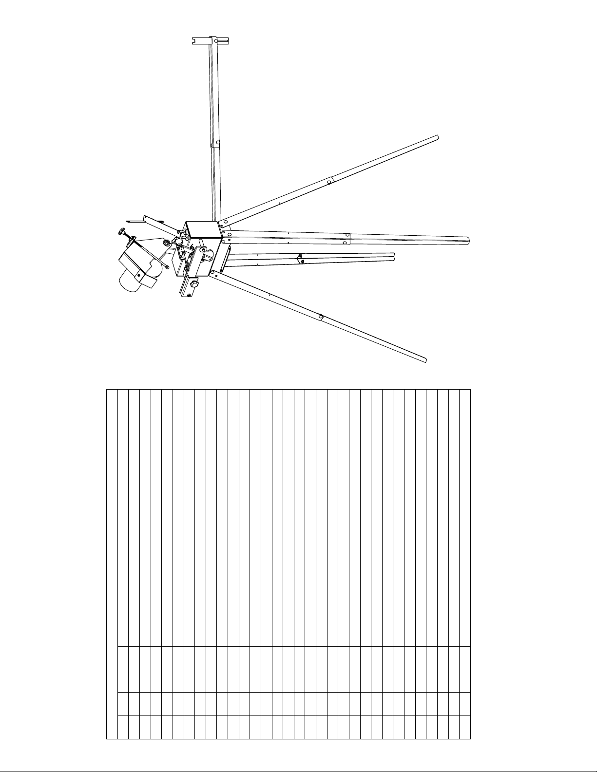
PARTS LIST
PARTS LIST
ITEM
QTY
PART NO
DESCRIPTION
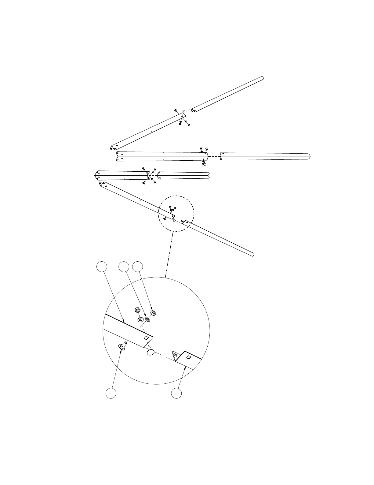
1 4 0001557
LEG PIECE A
2 4 0001558
LEG PIECE B
3 1 0001554
MOUNTING FLANGE
4 2 0001555
BLADE SUPPORT A
5 2 0001556
BLADE SUPPORT B
6 1 0001583
CONTROL BOX ASSEMBLY
7 2 0001559
BLADE GUIDE PLATE
8 1 0001600
GRINDING HEAD ASSEMBLY
9 1 0001567
MOUNTING ARM
10 1 0001553
GRINDING DISC, 6in OD, 1/4in THICK
11 1 0001570
GRINDING DISC NUT
12 1 0001579
M6 X 1.0 THREADED STUD
13 1 0001562
GRIND SHIELD
14 1 0001601
FEED LINK ASSEMBLY
15 1 0001751
KNOB, MULTI-LOBE, 50 mm OD, M10 X 1.5, 40 mm LG
16 2
6000-2RS
BALL BEARING, DOUBLE SEALED, 6000-2RS, 10 mm BORE, 26 mm OD, 8 mm WIDE
17 1
HDW
LOCK NUT, M10 X 1.5
18 3
HDW
FLAT WASHER, M10
19 2
HDW
FENDER WASHER, M10, 28 mm OD
20 1
HDW
HEX BOLT, M10 X 1.5, 65 mm LG, 26 mm LG THD
21 20
HDW
HEX NUT, M5 X 0.8
22 2
HDW
PRESSED WING NUT, M5 X 0.8
23 22
HDW
FLAT WASHER, M5
24 22
HDW
CARRIAGE BOLT, SQ NECK, M5 X 0.8, 12 mm LG
25 1
HDW
ACORN NUT, M6 X 1
26 1
HDW
HEX NUT, M6 X 1
27 1
HDW
KNOB, MULTI-LOBE, 32mm OD, M6 X 1.0, 12mm DEEP
28 1
HDW
KNOB, CIRCULAR KNOBBED, M6 X 1.0, THROUGH HOLE
29 2
HDW
HEX BOLT, M6 X 1, 15 mm LG
30 1
HDW
KNOB, 4 LOBE, 32mm OD, M6 X 1.0, 16.5mm LG
31 1
HDW
SCREW, TRH, No.8 X 3/8in LG