TABLE OF CONTENTS 1_______________________________________
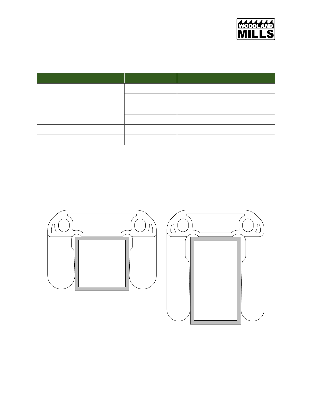
COMPATIBILITY 2_____________________________________________
VARIANTS 2__________________________________________________
DISASSEMBLY 3______________________________________________
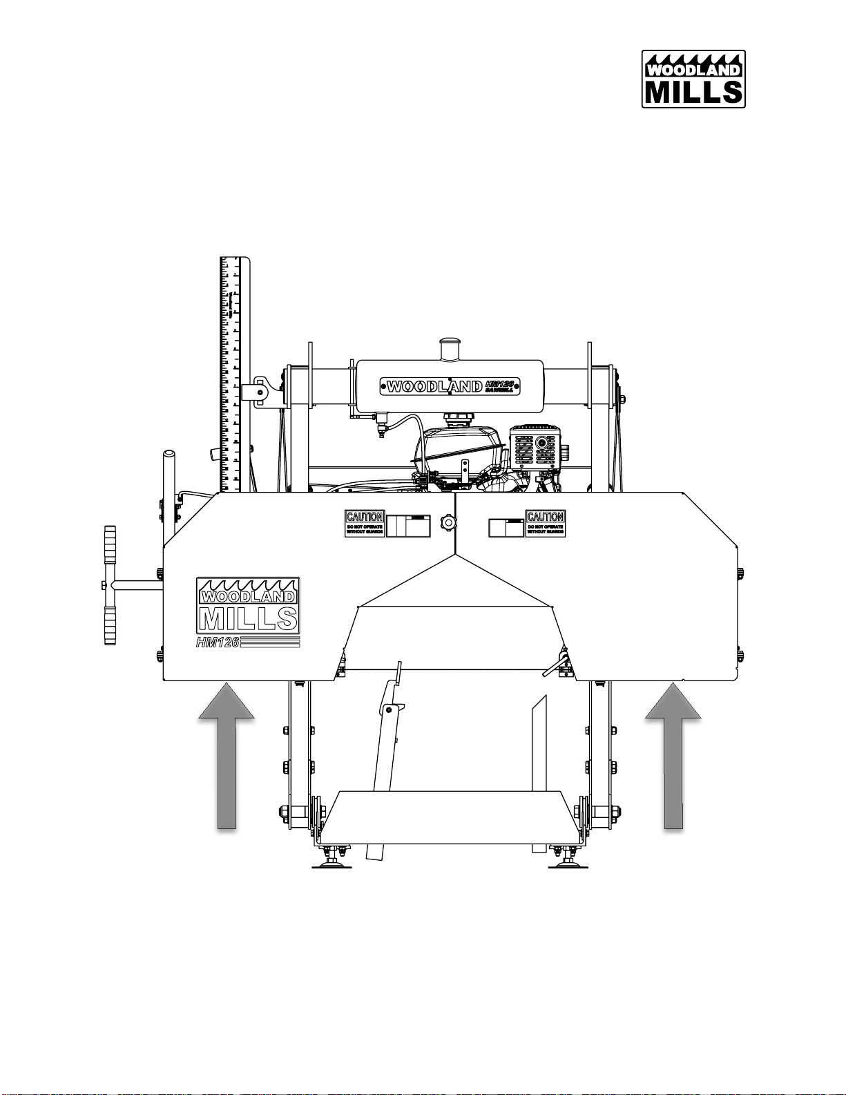
RAISE SAWHEAD 3_________________________________________
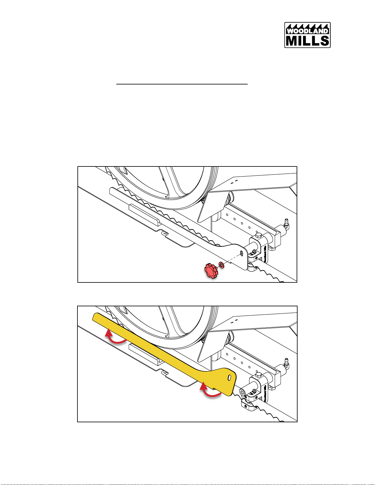
REMOVE ADJUSTABLE BLADE GUIDE 4________________________
REMOVE BLADE GUARD—HM126 & HM130MAX 4_______________
REMOVE BLADE GUARD—HM122 5____________________________
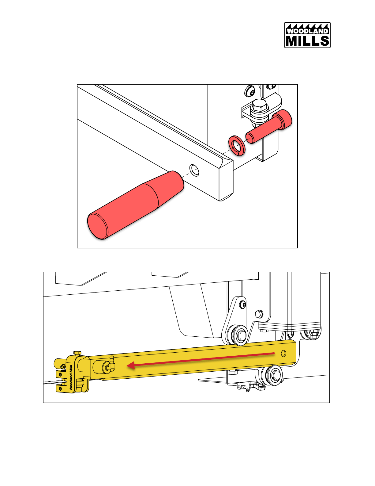
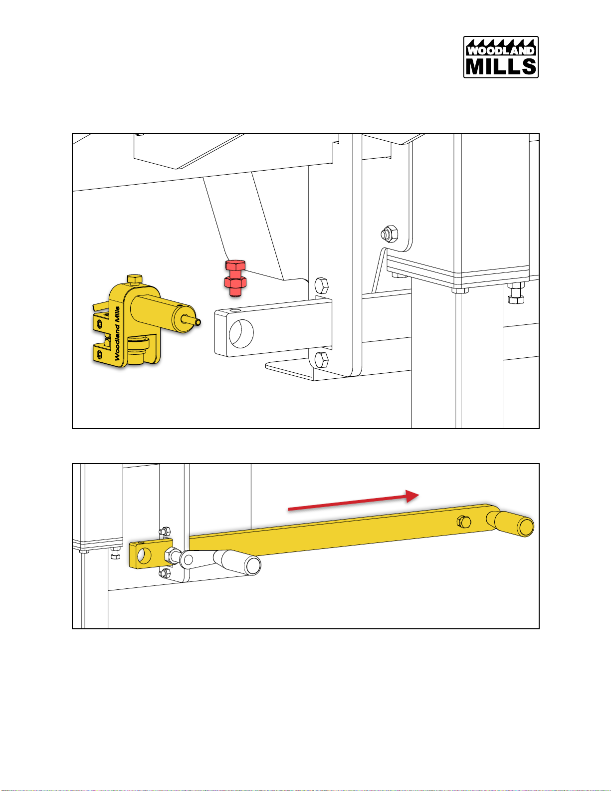
REMOVE GUIDE ARM—HM122, HM126 & HM130MAX 6___________
REMOVE GUIDE ARM—HM130 7_______________________________
REMOVE CARRIAGE—HM130MAX 9____________________________
REMOVE OLD POST SLEEVE BUSHINGS 10____________________
INSTALLATION 11_____________________________________________
ASSEMBLE UPPER POST SLEEVE BUSHINGS 11________________
ASSEMBLE LOWER POST SLEEVE BUSHINGS 12________________
FULLY TIGHTEN HARDWARE 14________________________________
ABG CALIBRATION—HM130MAX 15_____________________________