Woodpecker UDS-A User manual

Guilin Woodpecker Medical Instrument Co.,Ltd.
Website:www.glwoodpecker.com
ULTRASONIC PIEZO SCALER
INSTRUCTION MANUAL
(Please read this manual before operating)
UDS-A

Contents
1.The installation and components of equipment
1.1 Instruction
1.2 Components
1.3 The main technical specifications
1.4 Installation of the main components
2.Product function and operation
2.1 Scaling function
2.2 Endo function
3.Sterilization and maintenance
3.1 Sterilization of detachable handpiece
3.2 Sterilization of scaling tips,endo wrench and endochuck
3.3 Sterilization of torque wrench
3.4 Cleaning of tips,endochuck,torque wrench and endo wrench
3.5 Trouble analysis, solutions and notes
4.Precaution
4.1 Notice when using equipment
4.2 Contraindication
4.3 Storage and maintenance
4.4 Transportation
4.5 Working condition
5.After-service
6.Symbol instruction
7.Environmental Protection
1
1
1
3
3
7
7
9
10
10
10
10
11
11
13
13
14
14
14
14
15
15
16
8.For technical data, please contact 16
16
9. Declaration of conformity

1.1 Instruction
Guilin Woodpecker Medical Instrument Co., Ltd. is a professional
manufacturer in researching, developing and producing ultrasonic piezo
scaler. The product is mainly used for teeth cleaning and also an
indispensable equipment for tooth disease prevention and treatment. The
product UDS-A ultrasonic piezo scaler has scaling , perio and endo
functions. It contains the following features:
1.Automatic frequency tracking ensures that the machine always works
on the best frequency and more steadily.
2.The handpiece is detachable and can be autoclaved under the high
0
temperature of 135 C and the pressure of 0.22MPa.
3.Digitally controlled, easy operation and more efficient for scaling.
These features make UDS-A become a new generation product in the
world dental market nowadays.
1
1.The installation and components of equipment

Number
1
2
3
4
5
6
7
8
9
10
11
12
13
14
15
Description
Main unit
133mm × 58mm× 35mm
100mm × 62mm× 36mm
/
/
/
/
/
/
/
/
Detachable handpiece
Adapter of power supply
Foot switch
Scaling tip
Water line
Torque wrench
Handpiece decorative ring
Waterproof "o" ring
Packing list
Instruction manual
Warranty card
Qualified certificate
Endochuck
Endo wrench
Type
2
The Woodpecker scaling tips and their accessories are not listed in
this instruction manual completely. The detail can be found in the
instruction for tips and packing list attached to the machine.
18mm×117mm
6mm× 4mm
32mm×39mm
17mm× 15.4mm×2mm
3.2mm×1.1mm
1.2 Components
1.2.1 The following parts should be included in a complete"Woodpecker"
UDS-A ultrasonic piezo scaler
1.2.2 Product performance and structure
a)Ultrasonic piezo scaler is composed of electrocircuit, waterway and
ultrasonic transducer.
1.2.3 Scope of application
a)Ultrasonic piezo scaler UDS-A is used for the dental calculus
elimination and root canal treatment.

±
1.3 The main technical specifications
1.3.1 Technical specifications of ultrasonic scaler
a)Power source Input: 100V-240V~ 50Hz/60Hz 1.2A (max)
b)main unit input: 30VDC 1.3A
c)Output primary tip Vibration excursion:≤100μm
d)Output half-excursion force:<2N
e)Output tip Vibration frequency:28kHz 3kHz
f)Output power: 3W ~20W
g)main unit fuse: 250V/ T 1.6AL
h)power source fuse: 250V /T 2.0AL
i)Water pressure: 0.1bar~5bar (0.01MPa ~0.5MPa)
j)Weight of main unit:0.65kg
k)Weight of power source:0.3kg
l)main unit volume:184mm× 134mm × 80mm
m)Operating mode: Continuous operation
n) Type of protection against electric shock: Class II
o) Degree of protection against electric shock : Type BF equipment
p) Degree of protection against harmful ingress of water:Ordinary equipment
(IPX0) , Protection degree against water(used on the switch): IPX1
q) Degree of safety of application in the presence of a Flammable Anaesthetic
Mixture with air or with Oxygen or Nitrous Oxide:Equipment not suitable for
being used in the presence of a flammable anaesthetic mixture with air or with
oxygen or nitrous oxide
3

1.4 Installation of the main components
1.4.1 Sketch map for installation and connection.
a)The components of the equipment
4
Picture 1
Power s
witch
Socket for
foot switch
Socket for
power supply
Water entrance
Water control
knob
Scaling indicator
Endo indicator
Perio indicator
Options switch
Decreasing power
switch
Increasing power
switch
Power indicator

Picture 2
Picture 3
b、)Sketch map for connection of foot switch power supply and main unit
c)Sketch map for connection of wate supply system
5
Plug of
foot switch Foot s switch ocket
Foot switch
Plug of foot switch
Power supply
Socket for power supply
Power cord plug
Power cord plug
Input voltage 100V-240V~
Cap of one-way connector
Connect pure water
Water line
Water entrance

6
d)Sketch map for connection of detachable handpiece
Nipple
Seal
The connector of cable
Handpiece
Nipple Seal
Shaft
Handpiece
Picture 4
Autoclavable
symbol Brand CE mark The connector
of cable
Handpiece
Cable
e)Sketch map for how to install tip and endochuck with wrench
Picture 5
I
O
Torque wrench
Tip Handpiece
Screw on
Screw on
Screw on
Endochuck Endo wrench File

7
2.1 Scaling function
2.1.1Usage
a) Open the packing box, make sure that all the parts and accessories are
complete according to the packing list. Take the main unit out of the box
and put it on a stable plane.
b) Turn the water control switch to the max based on symbol as shown
as 3.5.2[note 1].
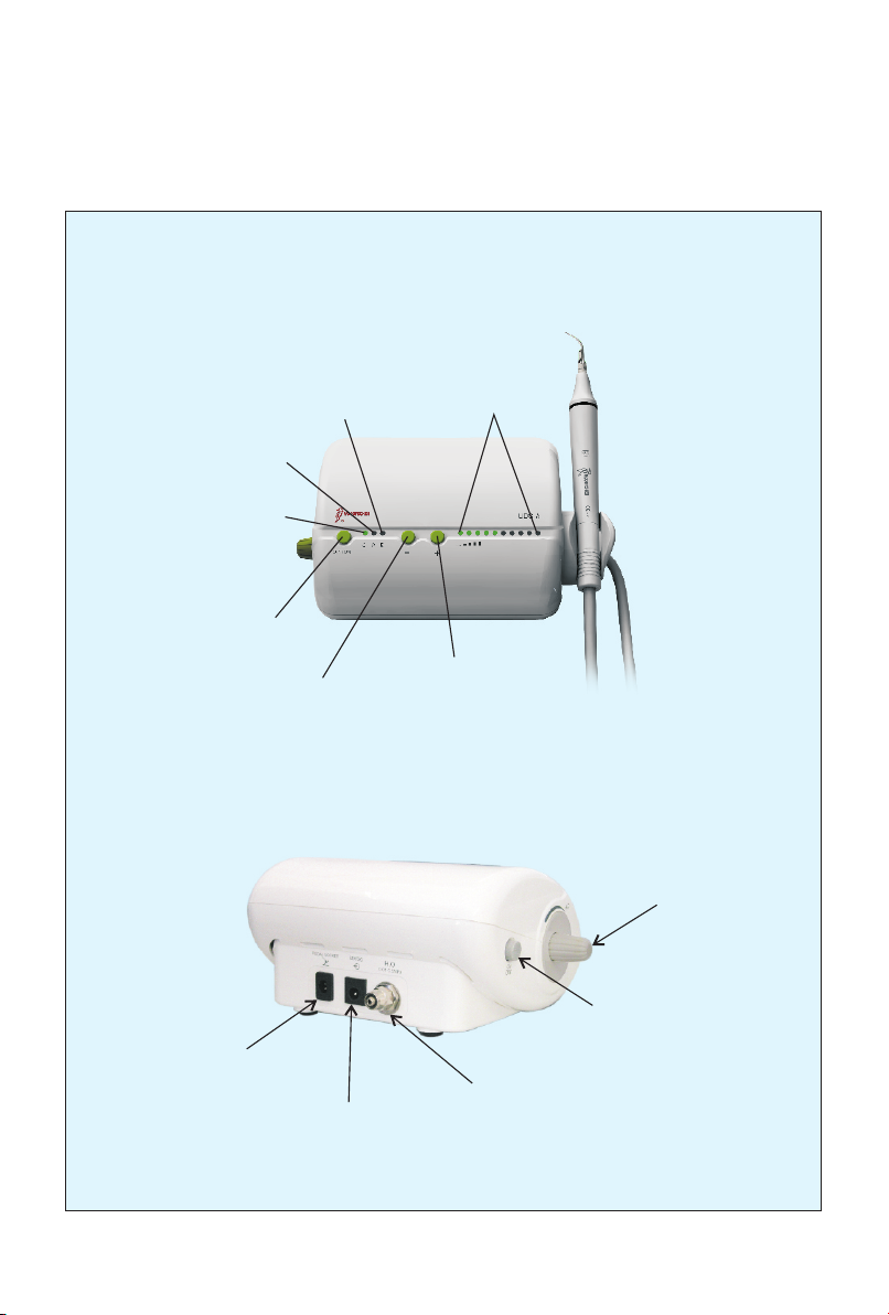
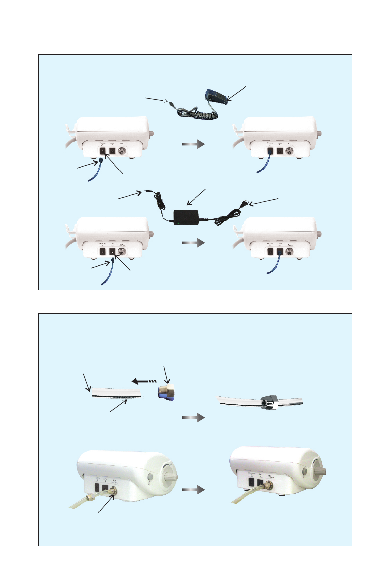
c) Insert the plug of the foot switch to its socket(picture 2).
d) Connect one end of the water line to the water entrance, and the other end
to the pure water source(picture 3).
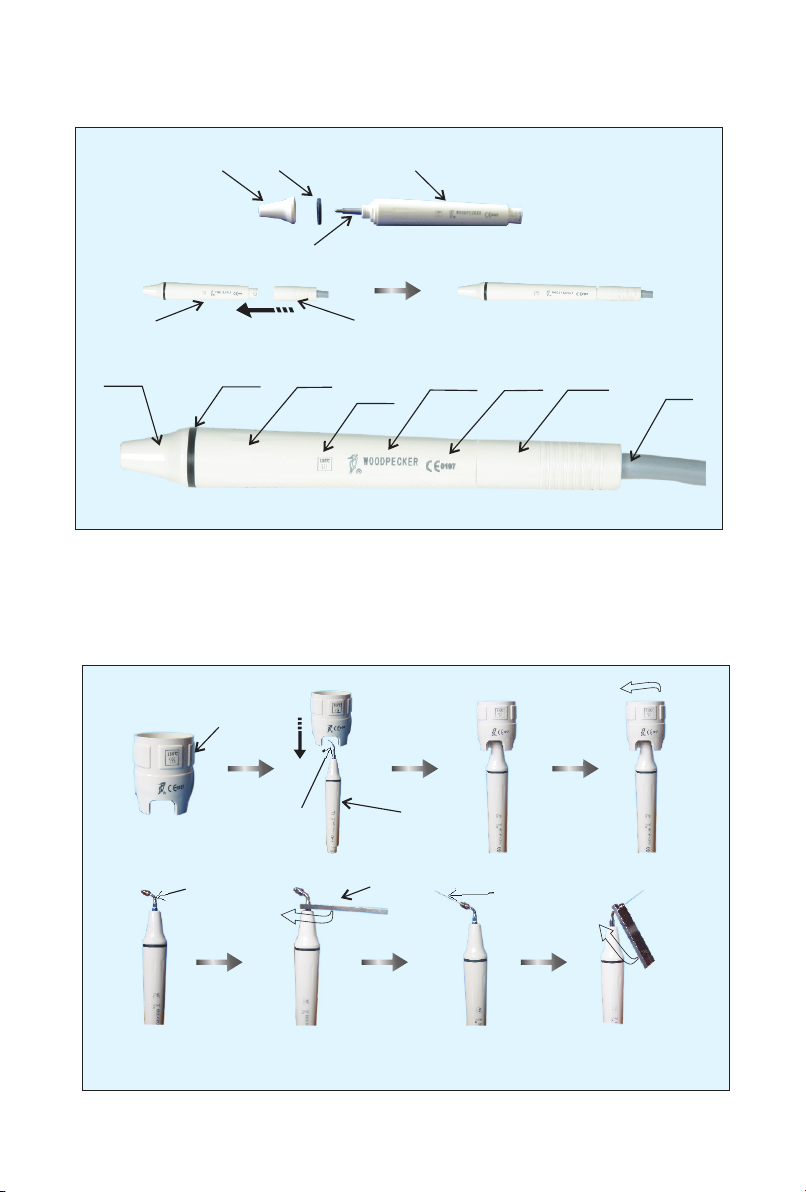
e) Screw the scaling tip tightly to handpiece by torque wrench, then connect
the handpiece and the connector of cable correctly.
f) Insert the plug of the power source to its socket ,then get through to
the electricity (picture 2).
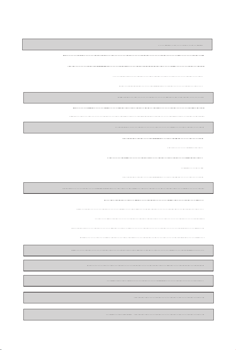
g) Switch on the main unit, then the scaling indicator and the first five lights
of power regulator shine.
h) Select a suitable scaling tip as you need, screw it on the handpiece tightly
by the torque wrench(picture 5).
i) The normal frequency is extremely high. Under the normal working state
of scaling tips , a light touch and a certain to-and-fro motion will eliminate
the tartar without heating. Overexertion and long-time lingering are forbidden.
j) Vibrating intensity: Adjust the vibration intensity as you need, generally
turn the knob to the middle grade. According to patients’ different sensitivity
and the rigidity of the gingival tartar, adjust the vibration intensity during the
clinical treatment.
k) Water volume adjust: Step on the foot switch, and the tip begins to vibrate,
then turn the water control switch to form fine spray to cool down the hand-
piece and clean the teeth.
l) The handpiece can be handled in the same gesture as a pen in hand.
2.Product function and usage

m) During the clinical treatment, be sure not to make the end of tip touch the
teeth vertically and not to make the tip overexert on the surface of the teeth
in case of hurting the teeth and damaging the tip.
n) After finishing operation, keep the machine working for 30 seconds on the
water supply condition in order to clean the handpiece and the scaling tip.
o) Unscrew the scaling tip and pull out handpiece, then sterilize them.
Notice: Don't pull out the handpiece when the foot switch is stepped on and
the machine is vibrating.
2.1.2 Instruction for main components of detachable handpiece (showed in
picture 4):
a) Nipple: The nipple can be removed. You can screw out the nipple and
clean the pole with alcohol termly.
b) Handpiece seal:The seal can be removed and cleaned with alcohol termly.
c) Handpiece: The main part of the whole handpiece, can be autoclaved under
the high temperature and pressure.
d) The connector of the cable:Connect the handpiece with the water source
and power supply of the main unit.
Notice: Keep dry when the detachable handpiece connect to the connector
of the cable.
2.1.3 Torque wrench use instruction (showed in picture 5)
a) The torque wrench's structure is designed in special way which can control
the strength of the scaling tip's installation properly and correctly. It also can
guarantee the operator screw or unscrew the scaling tip effectively and keep
their hands away from being scratched.
b) Operation
① Take the scaling tip into the torque wrench; operate as showed in picture 5.
② Tip installation: Hold the handpiece turn the tip toward direction as showed
In picture 5 with the torque wrench. Turn two more circles when the tip stops,
then the tip is installed.
③ Tip uninstallation: Hold the handpiece, turn the wrench toward anti-clockwise
8

direction.
④ Sterilize it in sterilizer after each treatment.
⑤ The torque wrench must be cooled naturally after sterilization to avoid
scald when using next time.
⑥ Keep the torque wrench in a cool, dry and ventilated place and be clean.
c) Precaution
The following sterilizing methods are forbidden.
① Braise in liquor;
② Dip in iodine,alcohol or glutaraldehyde;
③ Torrefy in oven or microwave oven.
Notice:we are not responsible for any damage of the torque wrench directly
or indirectly made by any way in the above items.
2.2 Endo function
a) Usage process
① Fix endochuck to handpiece by endo wrench.
②Unscrew the screw cap on the endochuck.
③ Put the ultrasonic file into the hole in the front of endochuck.
④ Screw down the screw cap with endo wrench to tight up the ultrasonic file.
⑤Press option key, turn to endo function.
⑥ When ultrasonic scaler turns into endo function, only the first lead light is
on and the power is at 1st grade. Put the ultrasonic file into the patient's root
canal slowly, step on the foot switch, then make endo treatment. During the
treatment, turn up the power gradually according to the needs.
b) Notice
① When fixing endochuck, it must be screwed down.
② The screw on the endochuck must be screwed down.
③Don't press it too much when the ultrasonic file in root canal.
④Don't start up the foot switch until the ultrasonic file is in root canal.
⑤The power range is supposed from 1st to 5th grades.
9

10
3.1 Sterilization of detachable handpiece
3.1.1 Autoclaved in high temperature/pressure:
0
a)121 C/1bar(0.1MPa), 20 minutes
0
b)135 C/2.2bar (0.22MPa), 18minutes
c) Pull out the handpiece and unscrew scaling tip and endochuck after each
operating.
d) Pack the handpiece with sterile gauze or sterile bag before sterilizing.
e) Reuse handpiece after it cools naturally in case of burning hand.
3.1.2 Notice
a) Clear the cleaning liquid on the handpiece with compressed air before
sterilization.
b)Be sure that the scaling tip has been unscrewed from the handpiece and it
cannot be sterilized with others.
c) Please notice whether the outer of the handpiece is damaged during the
treatment or sterilization, don't smear any protective oil on the surface of
handpiece.
d) There are two waterproof "o" rings at the end of handpiece. Please lub-
ricate them with dental lube frequently, as sterilization and repeated pull-
ing and inserting will reduce their using life. Change a new one once it is
damaged or worn excessively.
e) The following sterilizing methods are forbidden:
① Put handpiece into any liquid for boiling.
② Dip handpiece in disinfectors such as iodine, alcohol and glutaraldehyde.
③ Put handpiece into oven or microwave oven for baking.
3.2 Sterilization of scaling tips and endochuck
All the scaling tips and endochuck can be disinfected with alcohol cotton
or disinfected cloth. It's also ok to disinfect them by ultrasonic cleaner.
3.3 Sterilization of torque wrench and endo wrench
3.Sterilization and maintenance

11
a)The torque wrench and endo wrench can be disinfected by neutral non-
corrosive disinfector for cleaning and sterilizing, or be sterilized in high
temperature and pressure.
b) The following sterilization ways for torque wrench are forbidden:
① Braise in liquor;
② Dip in iodine, alcohol or glutaraldehyde;
③Torrefy in oven or microwave oven.
Notice: We are not responsible for any damage of the torque wrench directly
or indirectly made by any way in the above items.
3.4 Cleaning of tips, endocuck,torque wrench and endo wrench
The scaling tip,endochuck,torque wrench and endo wrench can be cleaned by
ultrasonic cleaner.
3.5 Trouble analysis , solutions and notes
3.5.1 Trouble analysis and solutions
Solutions
Possible causes
Phenomena of troubles
The scaling tip doesn't
vibrate and there is no
water flowing out when
getting through the
electricity. Contact our dealers or us
The fuse of transformer
is broken
Insert the foot switch
to its socket tightly
The foot switch
is in loose contact
Make the plug insert
to the socket well
The power line plug
is in loose contact
Dismantle the handpiece and
send it to our company to repair
Contact our dealers or us
Something wrong
with the cable
Something wrong
with the handpiece
The connect plug between
the handpiece and the circuit
board is in loose contact
Contact our dealers or us
Screw the tip on the
handpiece tightly (picture 5 )
The tip is in loose contact
The scaling tip doesn't
vibrate but there is water
flowing out when getting
through the electricity
The fuse in the main
unit is broken
Contact our dealers or us
Turn on the water control switch
【note 1】
Contact our dealers or us
The water system is blocked
There is impurity in the
electric-magnetic valve
The water control switch is
not on
The scaling tip vibrates
but there is no spray
when getting
through the electricity Clean the water line by
three-way syringe【note2】

The handpiece
generates heat
The water control switch is
in a low setting
Turn the water control switch
to a higher grade【note 2 】
The amount of spouting
water is too little
The water pressure is not
high enough Make the water pressure higher
The water line is blocked Clean the water line by
three-way syringe【note2】
Contact our dealers or us
There is impurity in the
electric-magnetic valve
There is still water
flowing out after the
power is off.
The vibration of the tip
becomes weak
The tip hasn't been screwed
on to the handpiece tightly
Screw the tip on the handpiece
tightly(as showed in picture 5)
The tip is loose because of
vibration
Screw on the tip tightly
(as showed in picture 5)
The coupling between the ha-
ndpiece and the cable isn't dry Dry it by the hot air
The tip is damaged【note3】Change a new one
There is water seeping from
the coupling between the
handpiece and the cable
The u-file doesn't vibrate
There is noise coming
from the endochuck
The waterproof "O ring
is damaged
"
The screw is loose
The screw is loose
Endochuck is damaged
Change a new "O " ring
Tighten it
Change a new one
Tighten it
12
If the problem still can't be solved, please contact with local dealer or manufacturer.
3.5.2 Notes
a) [Note 1] Turn the water control switch toward direction shown in symbol
till not be able to turn anymore, it comes to the min; on the contrary direction,
the water volume increases step by step till not be able to turn anymore.
b) [Note 2] Clean the water line with the three-way syringe of the dental
unit (as showed in picture 6):
Picture 6
Three-way syringe
I
O

① Cut the water line at a distance of 10cm~20cm from the water entrance.
② Turn on the electricity and get through the electricity.
③ Connect the three-way syringe of dental unit to the water line.
④ Disassemble the tip or handpiece.
⑤ Step on the foot switch.
⑥ Turn on the switch of the three-way syringe, press the water into the
machine and the impurity blocked in the water line can be eliminated.
c) [Note 3] If the scaling tip has been screwed on tightly and there is fine
spray too, the following phenomena show that the scaling tip is damaged:
① The vibrating intensity and the water atomization degree become weak
obviously.
② During treatment, it produces the sound like "buzz" from the scaling tip.
4.Precaution
4.1 Notice when using equipment
4.1.1 Keep the scaler clean before and after operation.
4.1.2 The handpiece, scaling tip,torque wrench, endo wrench and endochuck
must be sterilized before each treatment.
4.1.3 Don't screw or unscrew the handpiece, scaling tip and endochuck when
step on the foot switch.
4.1.4 The scaling tip must be fastened and there must be fine spray or drip
coming from the tip when operating.
4.1.5 Change a new one when the tip and ultrasonic file are damaged or worn
excessively.
4.1.6 Don't twist the tip and endochuck or rub them.
4.1.7 Don't use impurity water source and be sure not use normal brine instead
of purity water source.
4.1.8 If use the water source without pressure, the water surface should be one
meter higher than the head of the patient.
4.1.9 Insure the connector of handpiece and the socket of the cable dry before
installing the handpiece.
13

4.1.10 Don't pull the cable forcibly in case of the handpiece falling off the cable.
4.1.11 Don't knock or rub the handpiece.
4.1.12 After operating, turn off electricity source, then pull out the plug.
4.1.13 We are only responsible for the safety on the following conditions:
ⅠThe maintenance, repairment and modification are made by the manufacturer
or the authorized dealer.
ⅡThe changed components are original of "Woodpecker" and operated
according to instruction manual.
4.1.14 The internal screw thread of the scaling tips produced by some manufac-
tures is coarse, rusty and collapsed. This will damage the external screw thread
of the handpiece irretrievably. Please use "Woodpecker" brand scaling tips.
4.1.15 This model was only matched the adapter of our
company.
4.2 Contraindication
4.2.1 The hemophilia disease patient is not allowed to use this equipment.
4.2.2 The patients or doctors with heart pacemaker are forbidden to use this
equipment.
4.2.3 The heart disease patient, pregnant woman and children should be cautious
to use the equipment.
4.3 Storage and maintenance
4.3.1 The equipment should be handled carefully and lightly. Be sure that it is far
from the vibration, and installed or kept in a cool,dry and ventilated place.
4.3.2 Don't store the machine together with the articles that are combustible,
poisonous, caustic, and explosive.
4.3.3 This equipment should be stored in a room where the relative humidity
is≤80% , atmospheric pressure is 50kPa~106kPa, and the temperature is
0 0
-10 C~+50 C.
4.3.4 If not use for a long time, please make the machine get through the
electricity and water once per month for five minutes.
4.4 Transportation
4.4.1 Excessive impact and shake should be prevented in transportation. Lay it
carefully and lightly and don't invert it.
4.4.2 Don't put it together with dangerous goods during transportation.
4.4.3 Avoid solarization and getting wet in rain and snow during transportation.
14

We offer one year's free repair to the equipment from the date when it is sold
and lifetime maintenance.
The repair of the equipment should be carried out by our professional
technician. We are not responsible for any irretrievable damage caused by
the non-professional person.
15
Can be autoclaved
Alternating current
Type applied part BF
1 3 5℃
CE marked product
0197
Connection for the
foot switch
switch SOCKET
Adjustment for the
water flow
Power switch
H2O
30VDC power supply socket
FDA marked product
Trademark
Use indoor only
Class Ⅱ equipment
4.5 Working condition
0 0
a)Environment temperature:5 C~40 C
b)Relative humidity:≤80%
c)Atmosphere pressure : 50kPa~106kPa
6.Symbol instruction
5.After-service
Temperature limitation
Humidity limitation
Atmospheric pressure limitation
-10℃
+50℃106
50
0%
80%
Caution, consult
accompanying documents
EC REP
Date of manufecture
Authorised Representative in the
EUROPEAN COMMUNITY
Manufecturer

8 For technical data,please contact.
YAOTONG S.L.
MAYORISTA IMPORTACION Y EXPORTACION
C/:AUSIAS MARC 92-98 esc.C entre.3a
08013 BARCELONA ESPANA
TEL:0034-93 244 0204
16
7.Environmental Protection
There is not any harm factor in our product. You can deal with it based on
the local law.
We reserve the right to change the design of the equipment , the
technique , fittings , the instruction manual and the content of the
original packing list at any time without notice . If there are some
differences between blueprint and real equipment , take the real
equipment as the norm.
9. Declaration of conformity
9.1
EN 60601-1:1990+A1:1993+A2:1995+A13:1996
EN 60601-1-2:2001/EN 60601-1-4:2001
EN 61205:1994/EN ISO 22374:2005
EN ISO 14971:2000+A1:2003
EN 980:2003/ISO 9687:1993/EN 1041:1998
EN ISO 17664:2004/EN ISO 17665-1:2006
EN ISO 10993-1:2003/EN ISO 10993-5:1999/EN ISO
10993-10:2003+A1:2003
Product conformity the following standards:
16

Guidance and manufacturer’s declaration - electromagnetic emissions
The model UDS-A is intended for use in the electromagnetic environment specified below. The
customer or the user of the model UDS-A should assure that it is used in such an environment.
Emissions test Compliance Electromagnetic environment - guidance
RF emissions
CISPR 11 Group 1
The model UDS-A uses RF energy only for its internal function.
Therefore, its RF emissions are very low and are not likely to
cause any interference in nearby electronic equipment.
RF emissions
CISPR11 Class B
Harmonic emissions
lEC 61000-3-2 Class A
Voltage fluctuations
/ flicker emissions
lEC 61000-3-3
Not applicable
The model UDS-A is suitable for used in domestic establishment
and in establishment directly connected to a low voltage power
supply network which supplies buildings used for domestic
purposes.
Guidance & Declaration — electromagnetic immunity
The model UDS-A is intended for use in the electromagnetic environment specified below. The
customer or the user of the model UDS-A should assure that It is used in such an environment.
Immunity test IEC 60601
test level
Compliance
level
Electromagnetic environment -
guidance
Electrostatic discharge
(ESD)
lEC 61000-4-2
±6 kV contact
±8 kV air
±6 kV contact
±8 kV air
Floors should be wood, concrete or
ceramic tile. If floors are covered
with synthetic material, the relative
humidity should be at least 30 % .
Electrical fast
transient/burst
IEC 61000-4-4
±2kV for power supply
lines
±1 kV for Input/output
lines
±2kV for power
supply lines
Mains power quality should be that
of a typical commercial or hospital
environment.
Surge
lEC 61000-4-5
±1 kV differential mode
±2 kV common mode
±2 kV common
mode
Mains power quality should be that
of a typical commercial or hospital
environment.
<5 % UT
(>95% dip in UT. )
for 0.5 cycle
40 % UT
(60% dip in UT)
for 5 cycles
70% UT
(30% dip in UT)
for 25 cycles
<5% UT
(>95 % dip in UT)
for 5 sec
<5 % UT
(>95% dip in
UT.)
for 0.5 cycle
40 % UT
(60% dip in UT)
for 5 cycles
70% UT
(30% dip in UT)
for 25 cycles
<5% UT
(>95 % dip in
UT)
for 5 sec
Mains power quality should be that
of a typical commercial or hospital
environment . If the user of the
model UDS-A requires continued
operation during power mains
interruptions , it is recommended
that the model UDS-A be powered
from an uninterruptible power
supply or a battery.
Power frequency
(50/60 Hz)
magnetic field
lEC 61000-4-8
3 A/m Not applicable Not applicable
Voltage dips, short
interruptions and
voltage variations on
power supply input
lines
IEC 61000-4-11.
NOTE UT is the a.c. mains voltage prior to application of the test level.
9.2 EMC - Declaration of conformity
17

Guidance & Declaration - Electromagnetic immunity
The model UDS-A is intended for use in.the electromagnetic environment specified below. The customer or
the user of the model UDS-A should assure that it is used in such an environment.
Field strengths from fixed transmitters, such as base stations for radio (cellular/cordless) telephones
and land mobile radios, amateur radio, AM and FM radio broadcast and TV broadcast cannot be
predicted theoretically with accuracy. To assess the electromagnetic environment due to fixed RF
transmitters, an electromagnetic site survey should be considered. If the measured field strength in
the location in which the model UDS-A is used exceeds the applicable RF compliance level above, the
model UDS-A should be observed to verify normal operation. If abnormal performance is observed,
additional measures may be necessary, such as reorienting or relocating the model UDS-A.
Over the frequency range 150 kHz to 80 MHz, field strengths should be less than 3V/m.
a
b
Immunity test IEC 60601 test
level
Compliance
level Electromagnetic environment - guidance
Portable and mobile RF communications equipment
should be used no closer to any part of the model
UDS-A, including cables, than the recommended
separation distance calculated from the equation
applicable to the frequency of the transmitter.
Recommended separation distance
3V 3V
3 V/m
d=2.3×P1/2 800 MHz to 2.5 Ghz
where P is the maximum output power rating of the
transmitter In watts (W) according to the transmitter
manufacturer and d Is the recommended separation
distance in meters (m).
Field strengths from fixed RF transmitters, as
determined by an electromagnetic site survey,a should
be less than the compliance level in each frequency
range.b
Interference may occur In the vicinity of equipment
marked with the following symbol:
NOTE I At 80 MHz end 800 MHz. the higher frequency range applies.
NOTE 2 These guidelines may not apply in all situations. Electromagnetic propagation is affected by
absorption and reflection from structures, objects and people.
3 V/m d=1.2×P1/2 80 MHz to 800 MHZ
lEC 61000-4-6 150 kHz to 80 MHZ
Conducted RF
lEC 61000-4-3 80 MHz to 2.5 Ghz
3 Vrms
Radiated RF
18
This manual suits for next models
1
Table of contents
Other Woodpecker Media Converter manuals