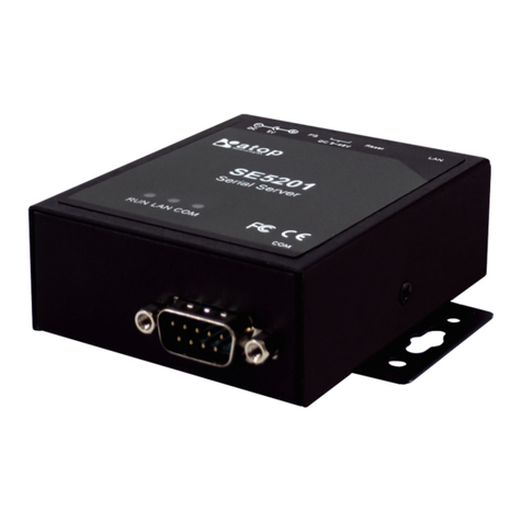
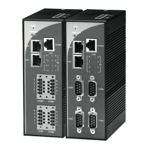
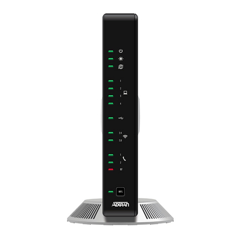
Atop PG59 Series User manual

eNode Designer
User Manual
錯誤! 使用 [常用] 索引標籤
將Heading 1,Product
Manual 套用到您想要在此
處顯示的文字。
Page | 1
Getting started with
PG59XX Protocol Gateway
Device Setup
Architectural overview
eNode Designer
User Manual
V1.6
December 12th, 2022
Atop Technologies, Inc.

eNode Designer
User Manual
錯誤! 使用 [常用] 索引標籤
將Heading 1,Product
Manual 套用到您想要在此
處顯示的文字。
Page | 2
This PDF Document contains internal hyperlinks for ease of navigation.
For example, click on any item listed in the Table of Contents to go to that page.
General Description
User Guide
Published by:
Atop Technologies, Inc.
2F, No. 146, Sec. 1, Tung-Hsing Rd,
30261 Chupei City, Hsinchu County
Taiwan, R.O.C.
Tel: +886-3-550-8137
Fax: +886-3-550-8131
www.atoponline.com
www.atop.com.tw

eNode Designer
User Manual
錯誤! 使用 [常用] 索引標籤
將Heading 1,Product
Manual 套用到您想要在此
處顯示的文字。
Page | 3
Important Announcement
The information contained in this document is the property of Atop technologies, Inc., and is supplied for the sole
purpose of operation and maintenance of Atop Technologies, Inc., products.
No part of this publication is to be used for any other purposes, and it is not to be reproduced, copied, disclosed,
transmitted, stored in a retrieval system, or translated into any human or computer language, in any form, by any
means, in whole or in part, without the prior explicit written consent of Atop Technologies, Inc.,
Offenders will be held liable for damages and prosecution.
All rights, including rights created by patent grant or registration of a utility model or design, are reserved.
Disclaimer
We have checked the contents of this manual for agreement with the hardware and the software described. Since
deviations cannot be precluded entirely, we cannot guarantee full agreement. However, the data in this manual is
reviewed regularly and any necessary corrections will be included in subsequent editions.
Suggestions for improvement are welcome.
All other product’s names referenced herein are registered trademarks of their respective companies.
Documentation Control
Author:
Charlie Yeh
Revision:
1.6
Revision History:
Software updates
Creation Date:
31 August 2016
Last Revision Date:
12 December 2022
Reviewer
Simon Huang
Product Reference:
PG59XX Protocol Gateway Family
Document Status:
Released

eNode Designer
User Manual
錯誤! 使用 [常用] 索引標籤
將Heading 1,Product
Manual 套用到您想要在此
處顯示的文字。
Page | 4
Table of Contents
1Introduction .......................................................................................................................7
1.1 Scope .......................................................................................................................................................7
1.2 Overview ..................................................................................................................................................7
1.2.1 List of Abbreviations.................................................................................................................................7
2Getting Started ..................................................................................................................8
2.1 Packing List..............................................................................................................................................8
2.2 How to order.............................................................................................................................................9
2.3 First Time Installation.............................................................................................................................10
2.4 Factory Default Settings.........................................................................................................................10
3Configuration and Setup.................................................................................................. 12
3.1 Configuration of Network Parameters through Device View..................................................................12
3.2 Configuration through Web Interface.....................................................................................................14
3.3 LCM (Liquid Crystal Matrix) Configuration (PG5916 only).....................................................................15
3.4 Automatic IP Assignment configuration with DHCP...............................................................................17
3.5 Web Overview........................................................................................................................................17
3.6 Network Configuration............................................................................................................................18
3.6.1 Link Aggregation ....................................................................................................................................19
3.6.2 Virtual IP settings ...................................................................................................................................20
3.7 Protocol Gateway...................................................................................................................................21
3.7.1 Redundancy Settings.............................................................................................................................21
3.7.2 IEC 61850 IED List - connection statistic...............................................................................................22
3.8 Advanced Settings .................................................................................................................................22
3.8.1 SNMP Settings.......................................................................................................................................22
3.9 VPN........................................................................................................................................................23
3.9.1 PPTP......................................................................................................................................................23
3.9.2 IPsec.......................................................................................................................................................25
3.9.3 Examples of IPsec Settings ...................................................................................................................32
3.9.4 Host-to-Host Connections......................................................................................................................33
3.9.5 Host-to-Network Connections ................................................................................................................34
3.9.6 OpenVPN ...............................................................................................................................................36
3.9.7 OpenVPN Setting...................................................................................................................................36
3.9.8 OpenVPN Keys......................................................................................................................................37
3.9.9 OpenVPN Status....................................................................................................................................40
3.10 System Setup.........................................................................................................................................41
3.10.1Time........................................................................................................................................................41
3.10.2Security ..................................................................................................................................................42
3.10.3Restart....................................................................................................................................................43
4General Description ......................................................................................................... 44
4.1 Protocol Gateway Overview...................................................................................................................44
4.2 Device Client/Master ..............................................................................................................................46
4.3 Device Server/Slave...............................................................................................................................46
4.4 Example –general settings....................................................................................................................47
4.5 Example - Polling process......................................................................................................................48
4.6 Example: Command process.................................................................................................................50
4.7 eNode Designer Overview .....................................................................................................................52
5eNode designer User Guide ............................................................................................. 53
5.1 Installation ..............................................................................................................................................53

eNode Designer
User Manual
錯誤! 使用 [常用] 索引標籤
將Heading 1,Product
Manual 套用到您想要在此
處顯示的文字。
Page | 5
5.2 Main Screen ...........................................................................................................................................54
5.3 Login.......................................................................................................................................................55
5.4 User Administration................................................................................................................................56
5.4.1 Creating, modifying and removing users................................................................................................56
5.4.2 Defining User Groups.............................................................................................................................57
5.5 Creating a project...................................................................................................................................59
5.5.1 Adding a Device (a.k.a. Target Platform or CFE) ..................................................................................59
5.5.2 Editing Ethernet Port Properties.............................................................................................................60
5.5.3 Editing Communication Port Properties .................................................................................................60
5.5.4 Adding an ADH Application to a Communication Port...........................................................................60
5.6 Data Points.............................................................................................................................................62
5.7 Viewing the Database of Data Points.....................................................................................................63
5.8 Generate and Send Configuration Files.................................................................................................63
5.8.1 Setting up the FTP Details .....................................................................................................................64
5.8.2 Send the Configuration ..........................................................................................................................64
6eNode designer Reference Guide .................................................................................... 67
6.1 Menu Bar Options ..................................................................................................................................67
6.1.1 File..........................................................................................................................................................67
6.1.2 Settings ..................................................................................................................................................67
6.1.3 Help........................................................................................................................................................67
6.2 Tree Menu Options.................................................................................................................................67
Table of Figures
Figure 3-1 - List of Devices on Network in Device Management Utility.................................................................... 12
Figure 3-2 - Pull-down Menu of Configuration and Network ................................................................................... 12
Figure 3-3 - Pop-up Window of Network Setting....................................................................................................... 13
Figure 3-4 - Authorization for Changes...................................................................................................................... 13
Figure 3-5 - Overview web page of protocol gateway................................................................................................ 14
Figure 3-6 –Overview Page ..................................................................................................................................... 17
Figure 3-7 –Network configuration Page, example on PG5900A/08A/16A ............................................................. 18
Figure 3-8 –Save completed Page........................................................................................................................... 19
Figure 3-10 –Bonding settings ................................................................................................................................. 19
Figure 3-10 –Bonding status .................................................................................................................................... 20
Figure 3-11 –Virtual IP settings................................................................................................................................ 20
Figure 3-12 –Redundancy settings........................................................................................................................... 21
Figure 3-13 –IED conncetion statistics..................................................................................................................... 22
Figure 3-14 –SNMP setting...................................................................................................................................... 23
Figure 3-15 VPN Scenario of SE/PG/MB 5901B ...................................................................................................... 23
Figure 3-16 PPTP configuration page....................................................................................................................... 24
Figure 3-17 PPTP Link Status................................................................................................................................... 24
Figure 3-18 An example of Host-to-Host Connection ............................................................................................... 25
Figure 3-19 Roadwarrior Application using Host-to-Subnet Connection .................................................................. 26
Figure 3-20 Gateway Application using Host-to-Subnet Connection........................................................................ 26
Figure 3-21 An example of network application using a subnet-to-subnet connection via the SE59XX and a peer
device........................................................................................................................................................................ 26
Figure 3-22 An example of host-network application via the subnet-to-subnet connection ..................................... 27
Figure 3-23 An example of host-host application via the subnet-to-subnet connection ........................................... 27
Figure 3-24 IPsec Tunnels Web Page under IPsec Setting Menu ........................................................................... 28
Figure 3-25 IPsec VPN Tunnel with Host-to-Host Topology..................................................................................... 33
Figure 3-26 General Settings for Host-to-Host with Static Peer ............................................................................... 33
Figure 3-27 General Settings for Host-to-Host with Dynamic Peer .......................................................................... 34
Figure 3-28 IPsec VPN Tunnel with Host-to-Network Topology............................................................................... 34
Figure 3-29 General Settings for Host-to-Network with Static Peer ......................................................................... 35
eNode Designer
User Manual
錯誤! 使用 [常用] 索引標籤
將Heading 1,Product
Manual 套用到您想要在此
處顯示的文字。
Page | 6
Figure 3-30 General Settings for Host-to-Network with Dynamic Peer .................................................................... 35
Figure 3-31 IPSec Link Status .................................................................................................................................. 36
Figure 3-32. OpenVPN Setting ................................................................................................................................. 36
Figure 3-33 OpenVPN Keys...................................................................................................................................... 38
Figure 3-34 Certification information......................................................................................................................... 39
Figure 3-35 Certificate Upload.................................................................................................................................. 39
Figure 3-36 OpenVPN client status........................................................................................................................... 40
Figure 3-37 OpenVPN server status......................................................................................................................... 40
Figure 3-38 –Time settings Page............................................................................................................................. 41
Figure 3-39 –Admin settings Page........................................................................................................................... 42
Figure 3-40 –Entering the User Name and the New Password ................................................................................ 42
Figure 3-41 –Restart page........................................................................................................................................ 43
Figure 4-1 –Protocol Gateway Application Example............................................................................................... 44
Figure 4-2 –Protocol Gateway Architectural overview ........................................................................................... 45
Figure 4-3 –Protocol Gateway Polling Process ...................................................................................................... 48
Figure 4-4 –Protocol Gateway Command Process ................................................................................................. 50
Figure 4-5 - eNode Designer overview. .................................................................................................................... 52
Figure 5-1 - eNode Designer Setup Installer ............................................................................................................ 53
Figure 5-2 - eNode Designer setup wizard. .............................................................................................................. 53
Figure 5-3 - eNode Designer main screen................................................................................................................ 54
Figure 5-4 - Splash screen and login window........................................................................................................... 55
Figure 5-5 - User administration principal................................................................................................................. 56
Figure 5-6 - Access user administration.................................................................................................................... 56
Figure 5-7 - Adding a new user................................................................................................................................. 57
Figure 5-8 - Changing a user's user group. .............................................................................................................. 57
Figure 5-9 - Adding a user group.............................................................................................................................. 57
Figure 5-10 - User group added................................................................................................................................ 58
Figure 5-14 - Adding a device to the project............................................................................................................. 59
Figure 5-15 - Device added to project....................................................................................................................... 59
Figure 5-16 –Network properties modified............................................................................................................. 60
Figure 5-17 - Editing communication port settings example..................................................................................... 60
Figure 5-18 - Add ADH Application to communication port example........................................................................ 61
Figure 5-19 - Choosing client or server..................................................................................................................... 61
Figure 5-20 - ADH Application added to project. ...................................................................................................... 61
Figure 5-21 - Adding data point references. ............................................................................................................. 62
Figure 5-23 - Data point view window....................................................................................................................... 63
Figure 5-24 - Access device settings to set FTP settings......................................................................................... 64
Figure 5-25 - Device settings window. ..................................................................................................................... 64
Figure 5-26 - Send configuration files window.......................................................................................................... 65
Figure 5-27 - Asked to reboot after sending configuration files. ............................................................................... 66
List of Tables
Table 3.1 Description of Parameters in IPsec Tunnels Web Page........................................................................... 31
Table 6-1 - Tree context menu options..................................................................................................................... 67

eNode Designer
User Manual
錯誤! 使用 [常用] 索引標籤
將Heading 1,Product
Manual 套用到您想要在此
處顯示的文字。
Page | 7
1Introduction
Thank you for Buying Atop’s Protocol Gateway.
The product is bundled with the following three user manuals:
1) Hardware specific installation user manual, not covered in this document. It covers Atop’s hardware
installation procedure, wiring, power connection etc.
2) Getting started with Atop’s Protocol Gateway: Basic Gateway configuration, Gateway architectural
overview and eNode Designer general instructions–this manual. This manual covers the installation,
network configuration, maintenance and using of the configuration tool software, including the procedure
to be followed for uploading new configurations to Atop’s device.
3) Protocol specific user manual, not covered in this document. Such manual covers:
a. Step-by-step protocol set-up between Client/Master –Server/Slave of the Protocols in eNode
designer
b. Description of the protocol-specific software features (of both protocols), the device profile and
the implementation table of supported functionalities.
1.1 Scope
This document is divided into four major sections:
•Getting started
•Basic Network Settings with WebGUI
•General Description : it explains the general Gateway architecture and the goals of eNode Designer and
its working principals.
•eNode designer User Guide : it walks the user through all features of the eNode Designer, specifically
explains how to add, delete, and edit projects and carry out device configurations.
1.2 Overview
1.2.1 List of Abbreviations
AAP = Alarm Annunciator Panel
ADH = Application Data Hub
CFE = Communication Front End
EDM = eNode Designer Module
FTP = File Transfer Protocol
PDF = Portable Document Format
RAM = Random Access Memory

eNode Designer
User Manual
錯誤! 使用 [常用] 索引標籤
將Heading 1,Product
Manual 套用到您想要在此
處顯示的文字。
Page | 8
2Getting Started
2.1 Packing List
Inside the purchased package, you will find the following items.
Table 2-1 Packing List
Item
Quantity
Description
PG59XX Series
1
Protocol Gateway
Mounting Kit
1
PG5901, PG5904D, PG5901B and PG5901E
⚫DIN-Rail Kit (x 1) or
PG5908, PG5916, PG5900A, PG5908A, PG5916A Series
⚫Rack Mounting Type-L angles (x 2)
⚫Screws (x 6)
Terminal block
PG5904D and PG5904D-Sis
⚫7-pin, 2ESDVM-07P (x 1)
⚫5-pin, EC381VM-05P (x 4) for PG5904D-Sis-X only
PG5901, PG5908, and PG5916 Series
⚫3-pin, 2ESDV-03P (x 1)
Documentation
1
Hardware Installation Guide (Warranty card is included)
Note:
•Notify your sales representative immediately if any of the above items is missing or damaged upon delivery.

eNode Designer
User Manual
錯誤! 使用 [常用] 索引標籤
將Heading 1,Product
Manual 套用到您想要在此
處顯示的文字。
Page | 9
2.2 How to order
Please refer to the following product codes to place an order.
Table 2-2 Product Codes
Item
Description
PG5901-X
1-Port Serial-to-Ethernet Protocol Gateway, Dual LAN, RS-232/422/485
software selectable, DIN-Rail type
PG5901B-X
1-Port Cellular to Ethernet and Cellular to Serial Protocol Gateway, LAN, one
RS-232/422/485 software selectable, DIN-Rail type
PG5901E-X
1-Port Serial-to-Ethernet Protocol Gateway with one Profibus port, Dual LAN,
one RS-232/422/485 software selectable, DIN-Rail type
PG5904D-X
4-Port Serial-to-Ethernet Protocol Gateway, Dual LAN, RS-232/422/485
software selectable, DIN-Rail type
PG5908-X (US)
8-Port Serial-to-Ethernet Protocol Gateway with RJ45 connectors, AC 100-
240V, US power plug
PG5908-X (EU)
8-Port Serial-to-Ethernet Protocol Gateway with RJ45 connectors, AC 100-
240V, EU power plug
PG5916-X (US)
16-Port Serial-to-Ethernet Protocol Gateway with RJ45 connectors, AC 100-
240V, US power plug
PG5916-X (EU)
16-Port Serial-to-Ethernet Protocol Gateway with RJ45 connectors, AC 100-
240V, EU power plug
PG5900A-X
Ethernet-to-Ethernet Protocol Gateway, 6 RJ45 or SFP ports,
IEC61850-3 certified hardware
PG5908A-X
8-Port Serial-to-Ethernet Protocol Gateway with DB9 or TB5 connectors, 6
RJ45 or SFP ports, IEC61850-3 certified hardware
PG5916A-X
16-Port Serial-to-Ethernet Protocol Gateway with DB9 or TB5 connectors, 6
RJ45 or SFP ports, IEC61850-3 certified hardware

eNode Designer
User Manual
錯誤! 使用 [常用] 索引標籤
將Heading 1,Product
Manual 套用到您想要在此
處顯示的文字。
Page | 10
2.3 First Time Installation
Before installing the device, please follow strictly all safety procedures described in the hardware installation guide
that is available inside the box or on Atop’s website. Atop will not be liable for any damages to property or personal
injuries resulting from the installation or overall use of the device. Do not attempt to manipulate the product in any
way if unsure of the steps described here. In such cases, please contact your dealer immediately.
When the device is running, connect it to computer to carry on network configuration. Connect LAN1 port to a
network switch or to your LAN with a UTP cable, and connect a host PC to your LAN with another UTP cable.
After network configuration is complete, it is possible to carry on protocol-specific settings. Protocol specific
configuration is made through eNode-Designer utility that is available for download online.
For more information on how to install the device, please refer to the Hardware Installation Guide leaflet available in
your package.
2.4 Factory Default Settings
Network Default Setting
The device comes with one IP address specifically for redundant Ethernet interfaces.
Table 2-3 Default Network Setting
Interface
Device IP
Subnet mask
Gateway IP
LAN 1
10.0.50.100
255.255.0.0
10.0.0.254
LAN 2
192.168.1.1
255.255.255.0
192.168.1.254
LAN 3-4-5-6 (*)
192.168.1.2
192.168.1.3
192.168.1.4
192.168.1.5
255.255.255.0
192.168.1.254
Remarks: Default DNS 1 setting is 192.168.1.254 and DNS 2 setting is 0.0.0.0. LAN 3-4-5-6 are available on PG59XXA
family only
Other Default Settings
Other default settings are shown in the following table:
Table 2-4 Other Default Settings
Parameter
Default Values
Security
User Name
admin
Password
default
SNMP
SysName of SNMP
0060E9-XXXXXX
SysLocation of SNMP
Location
SysContact of SNMP
Contact
SNMP
Disable (Unchecked)

eNode Designer
User Manual
錯誤! 使用 [常用] 索引標籤
將Heading 1,Product
Manual 套用到您想要在此
處顯示的文字。
Page | 11
Read Community
Public
Write Community
Private
SNMP Trap Server
0.0.0.0
Note: press the “Reset” button on the front panel for 5 seconds (see Sec. 3.9), to restore the Protocol Gateway to
the factory default settings.

eNode Designer
User Manual
錯誤! 使用 [常用] 索引標籤
將Heading 1,Product
Manual 套用到您想要在此
處顯示的文字。
Page | 12
3Configuration and Setup
It is strongly recommended for the user to set the Network Parameters through Device Management Utility© first.
The device-specific configuration can be carried out via Atop’s user-friendly Web-Interface.
3.1 Configuration of Network Parameters through Device View
First, please install Atop’s configuration utility program called Device Management Utility that can be downloaded
from our websites (www.atop.com.tw or www.atoponline.com). After running Device Management Utility, the
devices that are is already connected to the same subnet of the PC in use will be shown automatically. Device
Management Utility automatically detects the Protocol Gateway and lists it on Device Management Utility’s window.
Alternatively, the Protocol Gateway does not show up or is powered on after the software started, please press
“Rescan” icon. The list of devices currently connected to the network will be refreshed as shown below
Figure 3-1 - List of Devices on Network in Device Management Utility
Note: This figure is for illustration purpose only. Actual values/settings may vary between devices.
In the event the Protocol Gateway device is not in the same subnet of the PC. Therefore, please use Atop’s utility to
locate it in your virtual environment. To configure each device, click the selected device (default IP: 10.0.50.100) in
the list of Device Management Utility, and click “Configuration Network…” menu (or press Ctrl+N) or click on the
second icon called Network on the menu bar, and a pop-up window will appear as shown below.
Figure 3-2 - Pull-down Menu of Configuration and Network

eNode Designer
User Manual
錯誤! 使用 [常用] 索引標籤
將Heading 1,Product
Manual 套用到您想要在此
處顯示的文字。
Page | 13
Figure 3-3 - Pop-up Window of Network Setting
Then, proceed then to change the IP address manually. The system will prompt for access credentials to authorize
the changes. Please input the Username and Password. After confirmation, the device will be restarted with a beep.
After restart, the device will beep twice indicating that the unit is running normally. At this moment the Protocol
Gateway will be running on the new IP address. It will be listed automatically by Device View along with its old record
or it can be found by clicking on the Rescan icon.
Figure 3-4 - Authorization for Changes
Please consult your system administrator if you do not know your network’s subnet mask and gateway address.
Note: If your LAN address begins with 192.168.X.X, please use the LAN2 interface for configuration.

eNode Designer
User Manual
錯誤! 使用 [常用] 索引標籤
將Heading 1,Product
Manual 套用到您想要在此
處顯示的文字。
Page | 14
3.2 Configuration through Web Interface
PG59XX Protocol Gateway device is equipped with a built-in web server feature. Thus, the device can be accessed
with a web browser for configuration purposes simply by entering the device’s IP address (default IP address is
10.0.50.100) in the URL field of your web browser. If the user needs to change the IP address in order to access the
web-configuration, please go back to Sec. 3.1. The figure below illustrates the overview page of the web interface.
Figure 3-5 - Overview web page of protocol gateway
PG5900A/08A/16A, offer additional configuration options, such as redundancy, Virtual IP and Link Bond.
Configuring the device is user-friendly. Please go to its corresponding section for a detailed explanation.

eNode Designer
User Manual
錯誤! 使用 [常用] 索引標籤
將Heading 1,Product
Manual 套用到您想要在此
處顯示的文字。
Page | 15
3.3 LCM (Liquid Crystal Matrix) Configuration (PG5916 only)
The device also has the option of a configuration without using any software by using its interactive console. This
method is however very easy and immediate. Buttons and their functions are described next.
Table 3-1 LCM Button’s Description
Buttons
Button Description
Menu
<Menu>
Open Main Menu or Return to the previous menu
<Up>
Scroll up
<Down>
Scroll down
SEL
<SEL>
Select
Example
To change the device’s IP address, follow the instruction below.
◼Press <Menu> to enter Main Menu
◼Press <Down> to scroll down to 2. Network Set
◼Press <SEL> to enter Network setting and then <Up>/<Down> to scroll up or down to LAN1
◼Press <SEL> to enter LAN1 and then <Down> to scroll down to 1. IP Config
◼Press <SEL> to enter LAN1 IP Config and then press <Down> to scroll down to 1. Static, finally press
<SEL> to save the selection.
◼Press <SEL><Down> to enter 2. IP Address. Use <Up>/<Down> to increase or decrease the Digits of IP
Address, press <Menu> to return to one level higher after completion.
◼To enter: 3. Net mask, use <Up>/<Down> to increase or decrease the digits of subnet mask and then
<Menu> to return to one level higher after completion.
◼To enter: 4. Gateway, use <Up>/<Down> to increase the digits of default gateway and use <Menu> to
return to one level higher after completion.
◼Press <SEL> to the end of the menu to return to one level higher and the device shall display System
message “Save & Restart”. Push <SEL> to 2. Yes, and <SEL> again after completion. The device shall
restart and the new settings will appear.

eNode Designer
User Manual
錯誤! 使用 [常用] 索引標籤
將Heading 1,Product
Manual 套用到您想要在此
處顯示的文字。
Page | 16
The LCM command structure is summarized in Table 3-2.
Table 3-2 LCM Command Structure
1st layer
2nd layer
3rd layer
4th layer
Description
1.Overview
Model name
Display model name
Kernel ver.
Display kernel version
AP ver.
Display AP version
LAN 1
1.LAN status
Display status of LAN1
2.MAC
Display MAC address of LAN1
LAN 2
1.LAN status
Display status of LAN2
2.MAC
Display MAC address of LAN2
2.Network
set
1.LAN 1
1.IP config
1.Static IP
Display or change static IP
2.DHCP
Display dynamic IP or enable DHCP
2.IP address
Display or change LAN1 IP
3.Net mask
Display or change subnet mask
4.Gateway
Display or change the Gateway IP
2.DNS server1
Display or change 1st DNS IP address
3.DNS server2
Display or change 2nd DNS IP address
3.Server
state
1.Console
1.Web console
1.Disable
Disable web console
2.Enable
Enable web console
2.Telnet
console
1.Disable
Disable telnet console
2.Enable
Enable telnet console
2.Password
protection
1.LCM console
1.No
Disable LCM console password protection
2.Yes
Enable and change the password
2.Reset button
1.No
Disable the reset button password protection
2.Yes
Enable and change the password on reset button
3.Ping
1.LAN 1
Use "ping" command to check specific IP address for LAN1
2.LAN 2
Use "ping" command to check specific IP address for LAN2
4.Restart
1.No
Cancel restart command
2.Yes
Restart immediately

eNode Designer
User Manual
錯誤! 使用 [常用] 索引標籤
將Heading 1,Product
Manual 套用到您想要在此
處顯示的文字。
Page | 17
3.4 Automatic IP Assignment configuration with DHCP
A DHCP server can automatically assign addresses, Subnet Mask and Network Gateway to LAN1 or LAN2. You can
simply flag “DHCP (Obtain an IP Automatically)” checkbox in the Network Setting dialog using Atop’s Device View
utility and then restart it. Once restarted, the IP address(es) will be configured automatically.
3.5 Web Overview
In this section, current information on the device’s status and settings will be displayed. An example of PG5904D-
X’s overview page is shown below. This page will look different on each device.
Figure 3-6 –Overview Page
In detail, the following information is given:
◼Model Name, as its name implies, shows the device’s model.
◼Device Information displays information on the Kernel version as well as the AP version of the device.
◼Network Information shows the network properties of the two LAN ports

eNode Designer
User Manual
錯誤! 使用 [常用] 索引標籤
將Heading 1,Product
Manual 套用到您想要在此
處顯示的文字。
Page | 18
3.6 Network Configuration
In this section, IP address, Subnet Mask, Default (Network) Gateway, Domain Name System (DNS) and overall
connectivity settings can be accessed as shown in Fig.3-8. If you flag the DHCP checkbox, then IP address, Subnet
Mask, and Default (Network) Gateway will be assigned automatically.
Note1: It is not necessary to connect both ports. The user can connect only one LAN port to the Protocol Gateway device and change the network
settings.
Note2: the examples shown in the next pages refer to PG5900A/PG5908A/PG5916A. Other models do not support LAN bonding feature. These
features are only available on LAN1,2,3 of PG5900A/08A/16A.
Figure 3-7 –Network configuration Page, example on PG5900A/08A/16A
At the lower section in Figure 3-7, the DNS Servers can be set. This will allow the user to set the IP addresses of
Domain Name Server 1 (DNS 1) and Domain Name Server 2 (DNS 2). If the device is connected to the Internet and
should connect to other servers over the Internet (such as Network Time Protocol (NTP) server), the user will need
to configure the DNS server in order to be able to resolve the host name. Please consult the network administrator
or internet service provider (ISP) to obtain local DNS’s IP addresses.

eNode Designer
User Manual
錯誤! 使用 [常用] 索引標籤
將Heading 1,Product
Manual 套用到您想要在此
處顯示的文字。
Page | 19
After finishing the network settings configuration, click “Save & Apply” button to save all changes that have been
made. A Save Successful message will appear and after five seconds the web browser will be redirected to the
Overview page7.
Figure 3-8 –Save completed Page
3.6.1 Link Aggregation
Note: This feature is only available on PG5900A/PG5908A/PG5916A and on LAN 1,2,3.
In the LAN settings, the Physical LAN port bonding is possible in order to allow link aggregation. When two LANs are
configured to be in the same group, then only one port (Master) will be active and the other one will be in standby
mode. If the active port link is down, the standby ports will be activated.
The Link aggregation can be configured in the settings of each LAN port as per
Figure 3-9.
◼Enable: Check this box to enable link bonding feature. Default Unchecked
◼Master: Check this box to set this specific LAN port as Master. Default Checked
Please check the link aggregation status example in
Figure 3-10.
Figure 3-9 –Bonding settings

eNode Designer
User Manual
錯誤! 使用 [常用] 索引標籤
將Heading 1,Product
Manual 套用到您想要在此
處顯示的文字。
Page | 20
Figure 3-10 –Bonding status
3.6.2 Virtual IP settings
When Virtual IP settings are properly configured, multiple gateways on the same LAN will share the same IP address.
The purpose of this feature is to provide failover redundancy, since DCS/SCADA is not aware the number of
Gateways on the network if the intended IP address is the same.
When multiple gateways are set as Virtual IP hosts, internally one IP address owner (master host) will be auto-
negotiated between them and this will take an active role. The other devices will act as backup hosts. The Master
host will send keep-alive packets periodically and if the backup hosts don’t receive this for three times, a new master
host will be auto-negotiated, taking over the communication.
The meaning of the configuration fields shown in
Figure 3-11 are:
◼Enable: Enables Virtual IP address function. Default is disabled.
◼Virtual IP interface: Setup which physical LAN port will be the virtual IP interface.
◼Virtual IP address: Setup the Virtual IP address. The Virtual IP Address should be at the same subnet mask of
the selected interface.
Figure 3-11 –Virtual IP settings
This manual suits for next models
6
Table of contents
Other Atop Gateway manuals

Atop
Atop MB5404D-X Series Manual

Atop
Atop MB5201 Series Manual

Atop
Atop MB5400 User manual

Atop
Atop MB5404D Series User manual

Atop
Atop MB5001C User manual

Atop
Atop MB5001C User manual

Atop
Atop PG5901B Series Instruction sheet

Atop
Atop MB52 Series User manual

Atop
Atop SE5901 Series Manual

Atop
Atop PG5901B Series Instruction sheet