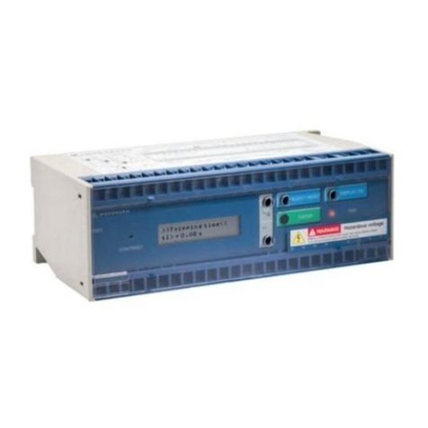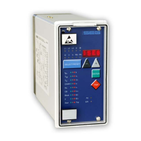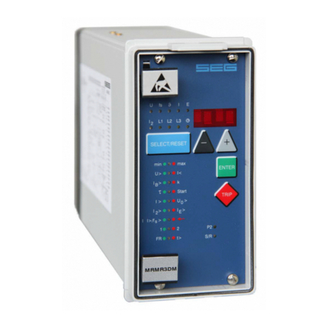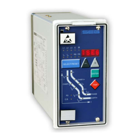
Manual XRN2 Woodward
DOK-TD-XRN2, Rev. D 3
Contents
1. Introduction and application........................................................................................5
2. Features and characteristics .......................................................................................6
3. Design............................................................................................................................7
3.1 Connections.............................................................................................................................................7
3.1.1 Analog input circuits.............................................................................................................................7
3.1.2 Blocking input.......................................................................................................................................7
3.1.3 Reset input...........................................................................................................................................7
3.1.4 Output relays........................................................................................................................................7
3.1.5 Power Supply.......................................................................................................................................8
3.1.6 Data communication............................................................................................................................8
3.2 Front plate................................................................................................................................................9
3.2.1 Indication- and operation elements......................................................................................................9
3.2.2 Display...............................................................................................................................................10
3.2.3 LEDs..................................................................................................................................................12
3.2.4 Front plate XRN2-1............................................................................................................................12
3.2.5 Front plate XRN2-2............................................................................................................................12
3.2.6 Parameter settings.............................................................................................................................13
4. Working principle........................................................................................................14
4.1 Analog circuits .......................................................................................................................................14
4.2 4.2 Digital circuits...................................................................................................................................14
4.3 Voltage supervision ...............................................................................................................................14
4.3.1 Selection of star or delta connection .................................................................................................15
4.4 Principle of frequency supervision.........................................................................................................16
4.5 Measuring of frequency gradient (XRN2-2)...........................................................................................16
4.6 Vector surge supervision (XRN2-1).......................................................................................................17
4.6.1 Measuring principle of vector surge supervision ...............................................................................19
4.7 Voltage threshold value for frequency measuring.................................................................................23
4.8 Blocking function....................................................................................................................................23
5. Operation and setting.................................................................................................24
5.1 Push buttons..........................................................................................................................................24
5.1.1 Indication of measuring values and fault data...................................................................................25
5.2 DIP switches..........................................................................................................................................26
5.2.1 Function of the output relays .............................................................................................................26
5.3 Reset......................................................................................................................................................27
5.4 Password...............................................................................................................................................27
5.4.1 Password programming.....................................................................................................................27
5.4.2 Using the password ...........................................................................................................................27
5.5 Relay setting principle............................................................................................................................28
5.5.1 Setting of default parameters.............................................................................................................28
5.5.2 Blocking the protection functions.......................................................................................................28
5.6 Display of software version and test-TRIP ............................................................................................28
5.7 Low/High range of functions blocking and reset....................................................................................29
6. Special settings...........................................................................................................30
6.1 Adjustable parameters...........................................................................................................................30
6.2Setting procedure ..................................................................................................................................31
6.2.1 Parameter setting of over- and undervoltage supervision.................................................................31
6.2.2 Setting of nominal frequency .............................................................................................................31
6.2.3 Number of measuring repetitions (T) for frequency functions ...........................................................31
6.2.4 Threshold of frequency supervision...................................................................................................32
6.2.5 Tripping delays for the frequency elements.......................................................................................32
6.2.6 Parameter setting of vector surge supervision (XRN2-1)..................................................................32
6.2.7 Parameter setting of frequency gradient (XRN2-2)...........................................................................33
6.2.8 Voltage threshold value for frequency and vector surge measuring (df/dt at XRN2-2).....................33
6.2.9 Adjustment of the slave address........................................................................................................33
6.2.10 Setting procedure for blocking the protection functions ................................................................33
6.3 Indication of measuring values..............................................................................................................34


