ZIEHL MS220VA User manual

ZIEHL industrie –elektronik GmbH + Co KG
Daimlerstr.13, 74523 Schwäbisch Hall, Germany
+ 49 791 504-0, [email protected]e, www.ziehl.de
Temperature Relays and MINIKA® Mains Monitoring Digital Panelmeters MINIPAN® Switching Relays and Controls Measuring Transducers Grid- and Plant Protection
Operating Manual MS220VA and MSR220VA
updated: 2019-02-06/Su
MS220VA and MSR220VA 11660-0701-03-GB Page
1
/ 12 www.ziehl.de
PTC thermistor relay with short-circuit detection
Marking see type plate on the device - type examination certificate PTB 12 ATEX 3006

MS220VA and MSR220VA 11660-0701-03-GB Page
2
/ 12 www.ziehl.de
Table of contents
1General Notes......................................................................................................................................... 3
2Display- and control elements............................................................................................................... 3
3Pre-Adjustment....................................................................................................................................... 3
4Application and brief description.......................................................................................................... 3
5Summary of features.............................................................................................................................. 4
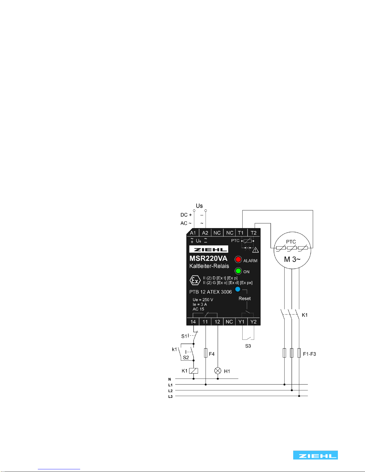
6Connecting diagram............................................................................................................................... 4
7Function diagram ................................................................................................................................... 5
8Important Notes...................................................................................................................................... 5
9Installation .............................................................................................................................................. 5
10 Commissioning....................................................................................................................................... 6
11 Operating instructions........................................................................................................................... 6
12 Trouble shooting and remedies ............................................................................................................ 6
13 Technical data ........................................................................................................................................ 6
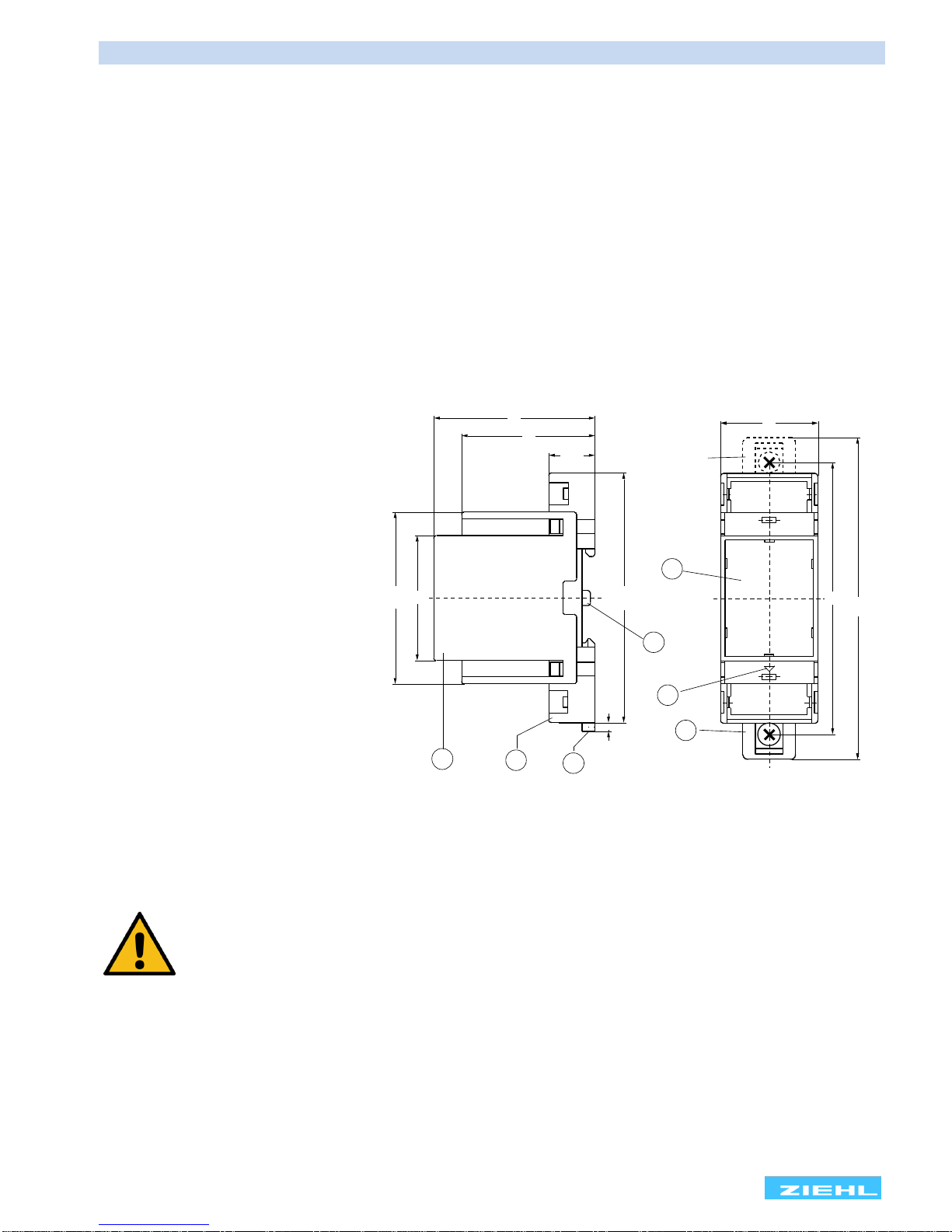
14 Dimensions - Design V2......................................................................................................................... 8
15 Safety Instructions and references for putting into operation............................................................ 8
15.1 Special remarks for explosive gas atmospheres areas (Zone 0, Zone 1 and Zone 2).................... 8
15.2 Special remarks for use in the presence of combustible dust! (Zone 20, Zone 21 and Zone 22).... 9
15.3 Safety characteristics of the safety device ..................................................................................... 9
15.4 Category and Performance-Level (EN ISO 13849-1)..................................................................... 9
15.5 Application of the safety device used with equipment category (EN 50495/VDE 0171-18)............. 9
15.6 Wiring.......................................................................................................................................... 10
15.7 Safe Separation........................................................................................................................... 10
15.8 Stop function................................................................................................................................ 10
15.9 Start and Restart.......................................................................................................................... 10
15.10 Manual resetting....................................................................................................................... 10
16 Proof testing of the safety functions................................................................................................... 11
17 Maintenance and repair........................................................................................................................ 11
18 EU-Declaration of conformity.............................................................................................................. 12

MS220VA and MSR220VA 11660-0701-03-GB Page
3
/ 12 www.ziehl.de
1 General Notes
Compliance with the following instructions is mandatory to ensure the functionality and safety of the product.
If the following instructions given especially but not limited for general safety, transport, storage, mounting,
operating conditions, start-up, maintenance, repair, cleaning and disposal / recycling are not observed, the
product may not operate safely and may cause a hazard to the life and limb of users and third parties.
Deviations from the following requirements may therefore lead both to the loss of the statutory material defect
liability rights and to the liability of the buyer for the product that has become unsafe due to the deviation from
the specifications.
2 Display- and control elements
1 = LED red „ALARM“
2 = LED green „Power ON“
3 = built-in key button “Reset”
3 Pre-Adjustment
No settings are necessary on the devices. The tripping temperature is determined solely by the response
temperature of the connected PTC thermistors.
Depending on the number of PTC thermistors the following tripping temperatures and reset temperatures
arise related to TNF (detector operating temperature):
Tripping temperature
Reset temperature
1 PTC thermistor
TNF + 15 K
TNF + 5 K
3 PTC thermistors in series
TNF + 5 K
TNF –5 K
6 PTC thermistors in series
TNF
TNF –20 K
4 Application and brief description
Ziehl PTC thermistor relays protect motors, transformers, machines and equipment against thermal overload.
Used in conjunction with respective PTC thermistors they provide a reliable temperature protection in the
temperature range 60 °C up to 180 °C.

MS220VA and MSR220VA 11660-0701-03-GB Page
4
/ 12 www.ziehl.de
ZIEHL PTC thermistor relays are conform to EN 60947-8 and are thus exchangeable. PTC-thermistors
according DIN 44081 and DIN 44082 shall be connected. PTC thermistors are suitable for the installation into
windings of electrical machines, bearings and transformers as well as to monitor the temperature of liquid
media, airflow and gases. With ATEX approval, explosion-protected equipment in explosive gas atmospheres
(marking G: gas) or in areas with combustible dust (marking D: dust) can be protected.
5 Summary of features
•1 thermistor circuit for 1…6 PTC thermistors
•Short-circuit detection within the thermistor circuit
•Output relay with 1 change-over contact (co)
•Operating status display with LED
A current monitors continuously the resistance of the sensors. In cold state, the resistance is <250 Ω per
sensor (sensor circuit < 1.5 kΩ). The relay has picked up and contacts 11/14 are closed. The resistance of
the thermistor rises rapidly at detector operating temperature TNF. The relay release at a resistance of 3…4
kΩ and contacts 11/12 close. The devices also switch off in the case of detector or line short-circuit (< approx.
20Ω) or detector or line interruption. MS types switch on automatically when the temperature has decreased
approx. 5 °C. MSR types store the switch-off and must be reset (to be acknowledged) manually with the built-
in key button or an external push-button. Power-on is recognized as an automatic reset. With bridged
terminals Y1 and Y2, the function reclosing-lock is disabled. Then the device works like type MS.
6 Connecting diagram
Us = supply voltage
S1 = off-switch
S2 = push-button on
S3 = remote reset only MSR type
H1 = indicator lamp fault
F1-F4 = fuses
K1 = contactor
PTC = PTC thermistor

MS220VA and MSR220VA 11660-0701-03-GB Page
5
/ 12 www.ziehl.de
7 Function diagram
MS220VA (automatic reset)
MSR220VA (reclosing lock)
Caution! The released relay switches on automatically after a voltage dip.
8 Important Notes
Attention!
Observe safety rules and standards. Notice safety remarks!
DANGER!
Hazardous voltage!
Will cause death or serious injury. Turn off and lock out
all power supplying this device before working on this device!
9 Installation
•The applicant must observe safety rules and standards.
•The device can be mounted on 35 mm rail according EN 60715 or with screws M4 (Option)
•The devices must be installed in a closed switchgear cabinet or in an enclosure of international
protection class IP 5x according EN 60529 or better.
•Terminals with screw mounting M3 maximum tightening torque 0,5 Nm

MS220VA and MSR220VA 11660-0701-03-GB Page
6
/ 12 www.ziehl.de
When installing the device into the switchgear cabinet, please observe the max. admissible
temperature. Care for both, sufficient clearance to other devices or sources of heat or
enough forced draught. If cooling is made more difficult, e.g. close devices with increased
surface temperature or by handicap of airflow cooling, the permissible ambient temperature
has to be reduced.
10 Commissioning
Attention!
Before switching on make sure that the operational voltage Us of the
Type plate and the mains voltage are the same!
After the supply voltage is switched on and when the thermistors are correctly connected the green LED „ON“
must light-up and the relay contacts 11,14 close.
The correct function of the tripping device must be checked by resistance simulation at terminals T1 and T2.
This check is also performed after changes to the installation.
11 Operating instructions
MSR220VA devices have an built-in reset button and can be manually reseted after a fault signal (Red =
alarm). For this purpose, also an external button (remote reset terminal Y1, Y2) can be used.
Terminals Y1 and Y2 may be bridged so the function reclosing-lock is disabled.
12 Trouble shooting and remedies
Relay does not pick up. Please check:
•The supply voltage Us at terminals A1-A2 (green LED lights-up).
•The PTC’s at terminals T1-T2. In the case of disturbance the red LED lights-up.
•The resistance of a PTC circuit must be at 50 Ω < R < 1500 Ω. The terminal voltage T1-T2 is to be
measured < 2.5 Vdc with connected PTC.
•MSR type: please push the key button “Reset”. The relay can pick up at resistance R < 1.65 kΩ and
the light changes from red to green. Alternatively reset can be done with closing an external contact at
terminals Y1-Y2 or with voltage recovery.
Relay does not release. Please check:
•With no PTC sensor connected the relay must release. The voltage at terminals T1-T2 must be
approx. 8 V.
In case of any other malfunctions, replace device. Please add a description of the occurred malfunction when
sending back for repair.
13 Technical data
Power supply (A1, A2)
Rated supply voltage Us:
(see type plate on the device)
AC 48 V
AC 110-120 V, AC 220-240 V, AC 380-415 V
AC / DC 24 V (ohne Potenzialtrennung)
Tolerance of voltage Us
AC 0.9 Us …1.1 Us DC 21 ... 30 V
Frequency (AC)
Tolerance of frequency
50 / 60 Hz
45 Hz … 65 Hz
Power consumption
< 2 VA < 2 W
On-period
100 %
Voltage dip buffer time
Max. 20 ms

MS220VA and MSR220VA 11660-0701-03-GB Page
7
/ 12 www.ziehl.de
Thermistor input (T1, T2)
PTC - Sensor acc. DIN 44081 and DIN 44082
Number
1 ... 6 PTC thermistor in series
Rated response temperature TFS
60 °C … 180 °C
Response tolerance
+/- 6° C
Collective resistance cold thermistor
≤1.65 kΩ
Terminal voltage (PTC thermistor)
≤ 2.5 V at R ≤ 3.65 kΩ, ≤ 2 V at R ≤ 1.65 kΩ
≤ 9 V at R =
Terminal current (PTC thermistor)
< 1 mA
Power consumption
< 2 mW
Line capacity max.
0,2 µF
Temperature monitor cut-out-point
3.3 kΩ…3.65 kΩ…3.85 kΩ
Temperature monitor reclosing point
1.7 kΩ…1.8 kΩ …1.95 kΩ
Short circuit monitor cut-out-point
≤ 20 Ω
Short circuit monitor reclosing point
≤ 40 Ω
Reset input (Y1, Y2)
Potential free contact (no)
Current
1 mA
Voltage
< 30 Vdc
Relay output (11,12,14)
EN 60947-5-1
Contacts
1 change-over contact (co)
Rated operational voltage Ue
250 V
Switching voltage/current
Max AC 415 V /5 A
Min 12 V /10 mA
Switching power max. (ohm resistive load)
1250 VA 120 W at DC 24 V
Rated operational current (Ie)
AC15 Ie = 3 A Ue = 250 V
DC13 Ie = 2 A Ue = 24 V
Recommended fuse
4 A (gG
Mechanical contact life
3 x 10⁷operations
Electrical contact life
1 x 10⁵operations at 240 V / 6 A
UL electrical ratings
250 V ac, 3 A, general use
240 V ac, 1/4 hp, 2.9 FLA
120 V ac, 1/10 hp, 3.0 FLA
C 300
Electrical Safety - Testing conditions
IEC/EN 60947
Contacts
1 change-over contact (co)
Rated insulation voltage Ui
300 V
Rated impulse voltage
4000 V
Overvoltage category
III
Contamination level
3
Transformer
EN 61558-2-6
Proof Test Voltage
2500 VAC 50 Hz
EMC - Immunity
EN 61000-6-2
EMC - Emission
EN 61000-6-3
Installation conditions
Fitting position
any
Rated ambient temperature range
-20 ... +55° C
Storage Temperature range
-10 …+70 °C (1K3 EN60721-3-1)
Alltitude
≤2000 m above see level
Climatic conditions
5-85% rel. F, no condensation (3K3 EN 60721-3-3)
Vibration resistance EN 60068-2-6
2…13.2 Hz ± 1 mm 13.2 ... 100 Hz ± 0,7 g

MS220VA and MSR220VA 11660-0701-03-GB Page
8
/ 12 www.ziehl.de
48
58
45
3
61,8
16,5
(90)
Option
98
116
35
3
4
12
5
7
6
Housing
Design V2
Dimensions (H x W x D) mm
90 x 35 x 58
Plastic Material
PA66
Fire protection class
UL 94 V-2
Protection class housing EN 60529
IP 30
Mounting EN 60715
standard rail 35 mm
Optional: Screw mounting
M4, only with additional bolt (not part of delivery)
Protection class terminals EN 60529
IP 20
Tightening torque
0.5 Nm
Line connection solid wire
1 x 0.5...2.5 mm2(AWG 22 –14)
Stranded wire with insulated ferrules
1 x 0.14 mm2…1.5 mm2
Insulation strip length min.
8 mm
Weight
approx. 117 g
Subject to technical modifications
14 Dimensions - Design V2
Dimensions in mm
1 Top
2 Bottom
3 Bolt
4 Seal mounting link
5 Front plate element
6 Characteristic for bottom
7 Extensible bolt for wall fastening with screws. Bolt bore Ø 4.2 mm.
15 Safety Instructions and references for putting into operation
–please read carefully!
15.1 Special remarks for explosive gas atmospheres areas (Zone 0, Zone 1 and Zone 2)
•The increased danger within hazardous areas requires the careful attention of the safety instructions
and references for putting into operation. Observe the national safety rules and regulations for
prevention of accidents as well as the European Standard EN 60079-14. All work for the connection,
for putting into operation and maintenance is to be implemented by qualified, responsible technical
personnel. Inappropriate behaviour can cause heavy personal damage and damages to property.
•The response of the thermal motor protection must directly switch off the motor, also when used
together with converters. This must be realized in the logic section or configuration in the converter.

MS220VA and MSR220VA 11660-0701-03-GB Page
9
/ 12 www.ziehl.de
•The tripping device may be installed only outside potentially explosive atmospheres for the protection
of explosive-protected motors. When used in potentially atmospheres, the device must comply with
the required type of protection.
15.2 Special remarks for use in the presence of combustible dust! (Zone 20, Zone 21 and Zone 22)
•The increased danger within hazardous areas of combustible dust requires the careful attention of the
safety instructions and references for putting into operation. Observe the national safety rules and
regulations for prevention of accidents as well as the European Standard EN 60079-14. Installation,
electrical connection and commissioning to be carried out by trained service personnel only.
Inappropriate behaviour can cause heavy personal damage and damages to property.
•The tripping device may be installed only outside potentially explosive atmospheres for the protection
of explosive-protected motors. When used in potentially explosive atmospheres, the device is to be
provided with a dust proofed enclosure according EN 60529.
15.3 Safety characteristics of the safety device
Safety Integrity Level (EN 61508) and safety related parameters
Operating mode
Hardware architecture
HFT
Safety Integrity Level
low demand mode
1001
0
SIL 1
Type
MTBF
PFH
SFF
SD
SU
DD
DU
MS220VA
54 years
4.07E-07
55%
4.44E-07
5.55E-08
0
4.07E-07
MSR220VA
52 years
4.26E-07
55 %
4.52E-07
6.10E-08
0
4.26E-07
Type
Proof test
interval T1
1year
3 years
5 years
10 years
MS220VA
PFDavg
1.78E-03
5.35E-03
8.91E-03
1.78E-02
MSR220VA
PFDavg
1.87E-03
5.60E-03
9.33E-03
1.87E-02
Observe proof test interval according EN 60079-17 for electrical equipment ≤ 3 years.
15.4 Category and Performance-Level (EN ISO 13849-1)
The devices fulfil the requirements of category 1 and PL = c. MTTFd= 100 years.
The data of the functional safety stated above are valid for an ambient temperature of 40 °C. Data for
additional ambient temperatures can be obtained on request.
15.5 Application of the safety device used with equipment category (EN 50495/VDE 0171-18)
This standard describes the minimum requirements of safety integrity level and fault tolerance of a safety
device in the application together with the category of the Equipment Ander Control (EUC).
EUC
Safety device
no safety device
SIL 1
SIL 2
Category 2
(2G, 2D)
EPL = Gb, Db
Zone 1, Zone 21
Zone 0, Zone 20
Zone 0, Zone 20
Category 3
(3G, 3D)
EPL = Gc, Dc
Zone 2, Zone 22
Zone 1, Zone 21
Zone 0, Zone 20
The tripping relay thus is suitable as safety device for Equipment Under Control (EUC) Category 3 (HFT = 0)
in Zone 1 and Zone 21 and for Equipment Under Control (EUC) Category 2 (HFT = 1) in Zone 0 and Zone 20.
The combined equipment shall comply with the relevant standards EN 60079-0 respectively EN 61241
according to the categories to match.

MS220VA and MSR220VA 11660-0701-03-GB Page
10
/ 12 www.ziehl.de
15.6 Wiring
•The lines of the thermistor circuit are to be routed as separate control lines as far as to the motor line.
The use of lines of the supply cable or other mainstream lines is not permissible. If extreme inductive
or capacitive stray effects are to be expected by parallel cables of the power installation, shielded
control lines should be used.
•Used with electronic speed regulation the thermistor lines must be routed separately from the power
lines as far as to the motor line, in order to avoid EMC distortion and thus false signal release.
•With devices type MSR the terminals Y1, Y2 may be attached parallel to a common resetting
mechanism. Sensor lines may not be connected together.
•The line resistance within the sensor circuit may not exceed a value of 20 Ω.
Maximum of permissible length for sensor circuit lines:
Wire cross section
Wire length
2,5 mm 2
2 x 1000 m
1,5 mm 2
2 x 800 m
1,0 mm 2
2 x 500 m
0,75 mm 2
2 x 300 m
0,5 mm 2
2 x 250 m
•With commissioning and after modification of the plant the sensor resistance must be checked with a
suitable measuring instrument. With a resistance < 50 Ω the sensor circuit is to be examined for short-
circuit.
Attention! Check PTC’s only with measuring voltages of < 2.5 V.
15.7 Safe Separation
•Line circuits (A1, A2, 11, 12, 14) have a safe separation to low-voltage electric circuits (T1, T2, Y1,
Y2).
•Trip relays with supply voltage DC/AC 24 V are permissible only at power supplies according EN
61558-2-6 where protected wiring is used.
15.8 Stop function
•A stop function released by the protection device must transfer the machine after manipulation of this
function as fast as possible into a safe condition. The stop function must have top priority.
•In case of failure the relay switches off the contactor/circuit breaker and so prevents an overheating of
the isolation system and/or the surface temperature. The protective function of the equipment is
guaranteed only if wiring is done directly into the control circuit of the motor/machine in accordance
with the connection diagram. The contacts must be protected, in order to prevent welding.
15.9 Start and Restart
•A restart may take place automatically only if no dangerous condition can be present. The tripping
devices of types MS 220 are equipped with an automatic reset function. For this device design,
suitable wiring of the control units must be ensured to prevent automatic restarting of the explosive-
protected motor of the type of protection Increased Safety „e“ in case of failure.
15.10Manual resetting
After introducing a stop instruction by the protection device this must be maintained, until the manual
resetting mechanism is operated and safe conditions for a renewed start are given. The manual
resetting may be only possible, if all safety functions and protection devices are effective.
•Trip devices types MSR have an electronic reclosing lock. The stop instruction remains, until by
pressing the push-button „Reset“ a reset is made. A start-up is only possible, if no case of failure
occurs and the motor is cooled down to a sufficient value of temperature. Trip devices type MSR
220VA switch on automatically with return of supply voltage. The user must guarantee by external
interlock (see connection diagram) so the supervised motor/machine does not start again
independently.

MS220VA and MSR220VA 11660-0701-03-GB Page
11
/ 12 www.ziehl.de
Attention!
Safety circuits according to EN 60204/EN 62061.
The tripping devices must not be used alone for functions, where an automatic
Restart must be prevented.
16 Proof testing of the safety functions
•The safety function shall be tested at regular intervals. It is recommended to carry out the proof-test
once a year. Depending on the zone risk, tests should be conducted more frequently. A fault is
recognized by the safety test. A fault between safety tests could cause loss of protection.
•The safety function must be tested by interrupt the thermistor circuit wire at terminals T1, T2.
•The short circuit monitoring function must be tested by bridging the thermistor circuit wires at terminals
T1, T2.
•The safety function must be tested by changing the resistance from 1500 Ohm to 4000 Ohm at
terminals T1, T2.
•The function of the electronic interlock must be tested additionally.
•If an error is detected no restart must be induced until the error is cleared.
17 Maintenance and repair
The devices are maintenance-free. Only the manufacturer may accomplish repairs. We recommend testing
within the regular maintenance intervals of the plant, where the device is used. EN 60079-17 is to be
observed.
You’ll find this and other user manuals in the internet under
www.ziehl.com
ZIEHL industrie –elektronik GmbH + Co KG
Daimlerstr. 13
74523 Schwaebisch Hall
Germany

MS220VA and MSR220VA 11660-0701-03-GB Page
12
/ 12 www.ziehl.de
18 EU-Declaration of conformity
EU-Declaration of Conformity
Erklärung/Declaration No. 11665-1300-02
Hersteller:
Manufacturer:
Ziehl industrie-elektronik GmbH + Co KG
Anschrift:
Address:
Daimlerstr. 13
74523 Schwäbisch Hall
Germany
Produktbezeichnung:
Product specification:
Kaltleiter-Relais
PTC Thermistor Relay
Typ:
Type:
MS220VA T222415
MSR220VA T222431
MSR220VA T222435
Wir erklären in alleiniger Verantwortung, dass
oben bezeichnetes Produkt den grundlegenden
Anforderungen entspricht die in den folgenden
Europäischen Richtlinien festgelegt sind:
We declare under our sole responsibility that
above designated product meets the basic
requirements and complies with the following
directives of the European Union:
2014/35/EU Niederspannungsrichtlinie
Low Voltage Directive
2014/30/EU EMV Richtlinie
EMC Directive
2014/34/EU ATEX Richtlinie
ATEX Directive
2011/65/EU RoHS Richtlinie
2015/863/EU RoHS Directive
Angewandte harmonisierte Normen und
technischen Spezifikationen:
Applied harmonised standards and technical
specifications:
EN 60947-8:2003 + A1:2006 + A2:2012
EN 61000-6-2:2005 + AC:2005
EN 61000-6-4:2007 + A1:2011
EN 50495:2010
EN 50581:2012
Benannte Stelle und Nummer der EG-
Baumusterprüfbescheinigung:
Notified Body and number of the EC-type-
examination certificate:
PTB Physikalisch Technische Bundesanstalt 0102
PTB 12 ATEX 3006
Schwäbisch Hall, 30.01.2019
Ort, Datum der Ausstellung
Place, date of issue
CE-Kennzeichnung: 2012
CE marking in:
ppa.
i.V.
Herbert Wahl Bernhard Scheu
Verkaufsleitung Qualitätsmanagement
Other manuals for MS220VA
2
This manual suits for next models
1
Table of contents
Other ZIEHL Relay manuals

ZIEHL
ZIEHL TR250 User manual

ZIEHL
ZIEHL MSR820V User manual

ZIEHL
ZIEHL EFR4001IP User manual

ZIEHL
ZIEHL STWA4MH User manual

ZIEHL
ZIEHL VG1200 User manual

ZIEHL
ZIEHL STW1K User manual

ZIEHL
ZIEHL STW1000V2 User manual

ZIEHL
ZIEHL TR 800 Web User manual

ZIEHL
ZIEHL MS220KA User manual

ZIEHL
ZIEHL TR 800 Web User manual

ZIEHL
ZIEHL TR 800 Web User manual

ZIEHL
ZIEHL COSFI100V User manual

ZIEHL
ZIEHL STW20K User manual

ZIEHL
ZIEHL UFR1001E User manual

ZIEHL
ZIEHL TR1200IP User manual

ZIEHL
ZIEHL TR250 User manual

ZIEHL
ZIEHL MS220VA User manual

ZIEHL
ZIEHL MS220KA User manual

ZIEHL
ZIEHL TR111V User manual

ZIEHL
ZIEHL UFR1001E User manual