Workhorse Freedom 6/8 User manual

PN: 67-1500, REV: A, 4/12

2
The Freedom is the epitome of simple as it relates to screen prinng. It’s simple to set up, simple to operate, and simple to maintain. That
said, The Freedom does not limit you to simple designs or small jobs. This machine turns any manual press operator into a mass producing
printer. Freedom’s fast indexing speed, simple to use controls and precise micro registraon ensure that setups are as fast and easy as
with your manual press. Add our patented FlashBack to the Freedom and Workhorse has re-wrien the book on aordable high
producon while keeping it simple. Automang your manual shop gives you freedom from: long hours at the press, aching elbows and
wrists, late deliveries, high labor costs, and the list goes on.
Congratulaons on your purchase of
the Workhorse Products Javelin Pro
Automac Texle Prinng Press.
Check the crate for damage, DO NOT
accept the crate if damaged due to
improper handling during shipping.
Report any damage to the carrier at
once as well as Workhorse Products at
800-778-8779.
Inspect the crate contents
IMMEDIATELY while the carrier is sll
there. Our packaging has been
carefully designed to handle normal
shipping condions. However, we
cannot be responsible for damage by
the carrier. Upon rst sight of freight
damage nofy or point out to the
driver and le your claim with the
carrier, then nofy us.
Two year limited warranty
Micro processor controlled
Fast, easy, squeegee and ood angle, pressure adjustments
Sing or double print strokes per screen for darker garments
Independent head controls
Non-warping solid aluminum platen
Adjustable rear screen clamp
Adjustable print stroke
Foot pedal
Features:
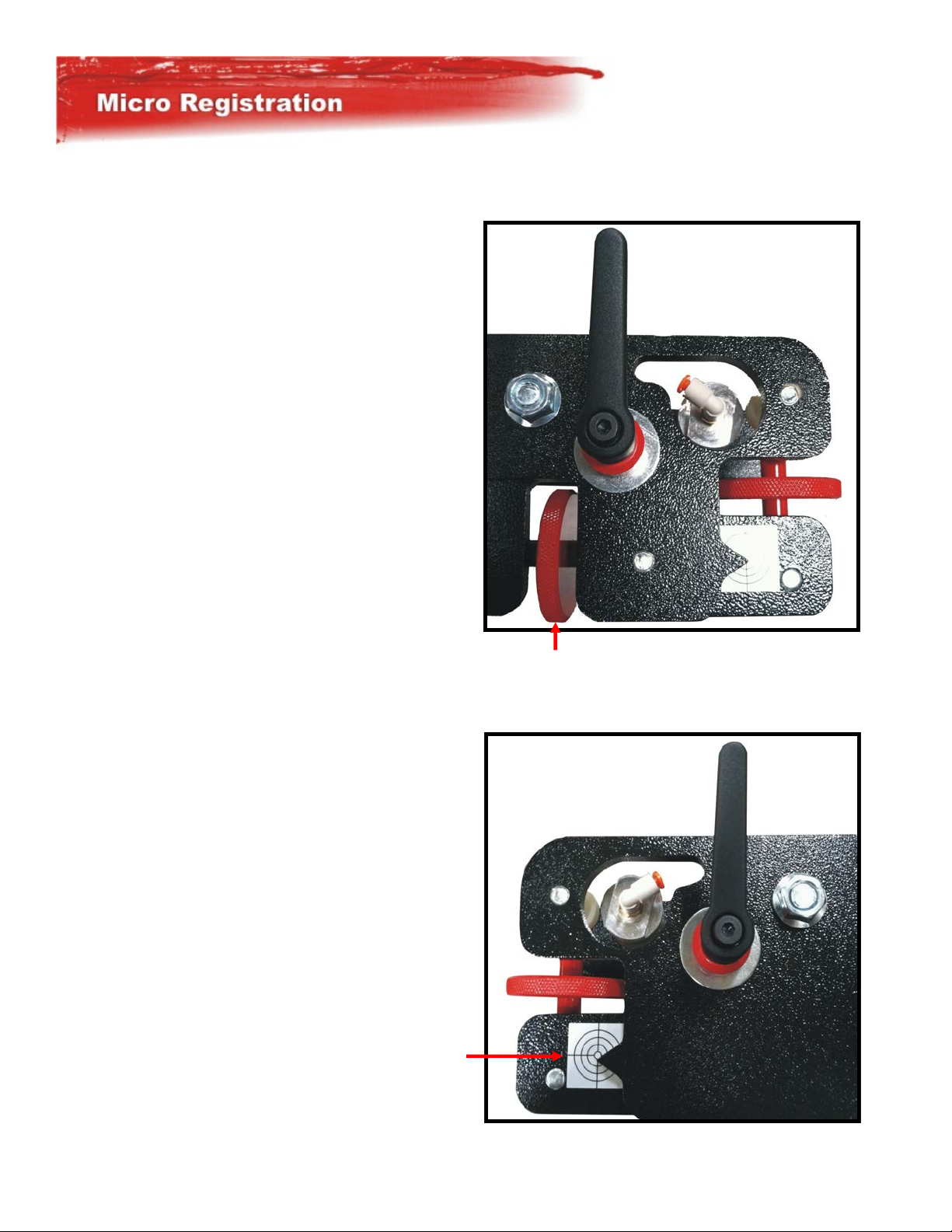
Micro registraon front & back for fast setups
heavy duty steel construcon throughout
Easily adjustable screen clamps
One knob quick change squeegee
Precision milled Registraon forks for exact registraon
Producon Counter
Variable o-contact adjustment
Easy release platens
60 doz./hr capability
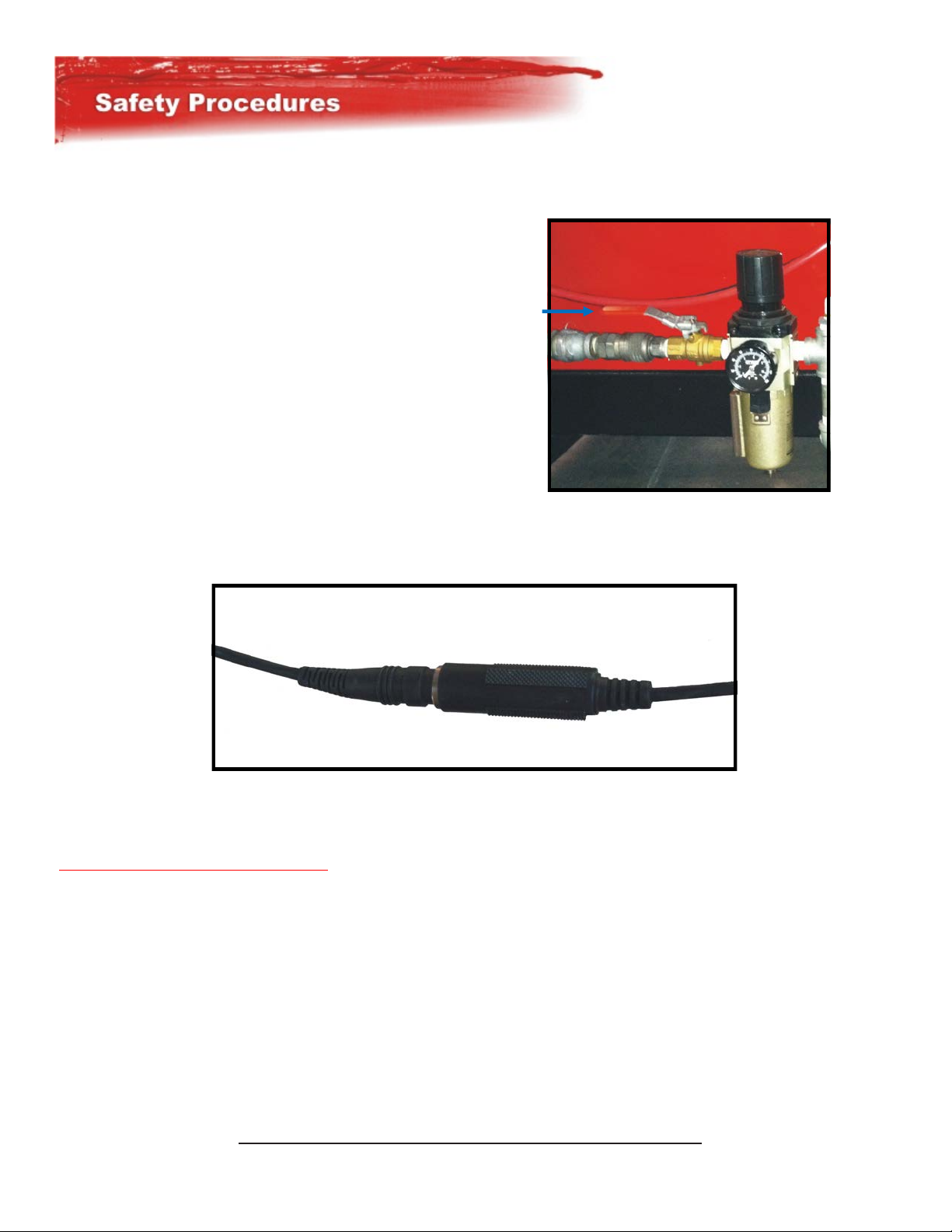
Integrated safety system

3
Questions? Give us a call!
800.778.8779
workhorseproducts.com
Visit our website at
Press Foot Print Compressor HP Rang CFM @ 120psi Volts Amps
FRD-6/8 10'5" (3.2m) 7.5hp 22cfm (7.6bar), (623 l/m) 110V, 50-60Hz, 10
Accessory Foot Print Was Volts Amps Phase
FlashBack 16” 2’ (extends from press) 4200W 220V 20 Single
FlashBack 20” 2’ (extends from press) 5500W 220V 25 Single
Radiant In-Head Installs In-Head 3015W 220V 14 Single
Max Print Area Portrait Posioning Landscape Posioning
FRD-6/8 16 x 18” 30 x 18”

4
1. MAIN AIR LOCKOUT VALVE: When servicing of the printer is required a special Lockout Valve has been provided as an added
safety precauon. This valve is located before the main lter/regulator. This has a padlock hole through it. A padlock may be
inserted to prevent air from being supplied to the printer.
SAFETY FIRST:
Always operate this or any other equipment safely. This equipment has heavy moving parts, which can cause serious injuries if all
safety precauons are not observed.
DO NOT OPERATE THIS EQUIPMENT WITHOUT THE SAFETY CABLES IN PLACE AND OPERATIONAL.
Do not allow anyone not fully trained on the operaon of this equipment to come within 3 feet of this equipment when in
operaon. Do not allow children near this equipment at anyme. Do not allow this equipment to operate while unaended.
Disconnect the power source when crawling under the Safety Cable or the extended circumference of this equipment. Do not
commence the operaon of this equipment without some type of LOUD vocal warning such as "CLEAR". Do not commence the
operaon of this equipment without visual inspecon to insure that no personnel are within the operaon area of the equipment.
USE COMMON SENSE. - THIS IS HEAVY EQUIPMENT.
DURING AN EMERGENCY SITUATION: Push the emergency stop buon or disconnect the safety cables.
NOTE: IT IS VERY IMPORTANT THAT THE TABLE BE IN ALIGNMENT BEFORE RECONNECTING THE SAFETY CABLE.
2. SAFETY CABLES: Located around the perimeter of the printer, when disconnected at any juncon they will cut power to all main
controls and energize the main Dump Valve emptying all of the air from the machine.

5
The way you tape your screens if you plan to run more then a few dozen shirts is very important. To minimize emulsion
breakdown, you should tape the enre back of your screen within an inch of your image area. Take extra care to ensure you have
covered the area where the squeegee rests at both ends, and where the edges of the squeegee run along the screen when
ooding and prinng. If the image stops before the edge of the pallet, tape the underside of the screen to protect from the sharp
pallet edge. Taping the inside of the screen in the squeegee path may damage your squeegee edge.
It is necessary that you pre-register your screens when burning them for the automac. The highest printed part of your total
image should be no closer then 6-1/2" from the top outside edge of your screen frames. You must also center your total image
(le to right). The end result of this preregistraon is if you were to stack all three (3) screens of a three (3) color job and look
through them, your image would be in registraon, try to keep within 1/8" tolerance when burning screens.

6
1
2
3
45678910 11 12 13
14
15
16
1718
1. Print Head Selector Switch: Each print head has its own selecon switch that is independent of all others and may be set in any
one of the following posions; OFF - Single, Print Stroke & Double Stroke. During a print cycle those heads in the OFF posion will
remain at rest. The remaining head(s) will print aer the pallet table has raised up, then upon compleon the pallet table will
lower and rotate to the next staon while the ood stroke is occurring. If a double print stroke is required for any head(s), the
pallet table will not rotate aer lowering but will rise again in the same posion for the second print cycle before connuing to the
next staon.
2. Manual Print Buons: Each print head has its own numbered buon, when one is depressed the pallet table will raise and the
corresponding print head will print. The table will then lower but no table rotaon will occur (used primarily to check registraon).
3. Emergency Stop Buon: When acvated the air pump valve will cycle and release all air from the printer and cut power to all
systems. (Note It is very important that the table be in alignment before reenergizing the emergency stop).
4. In Posion Indicator: Before the press can begin any cycle or command the press must be “in posion” meaning the correct
sensors are reading for the command to begin.
5. Front/ Rear: Front Posion; The squeegees will remain in the printed-rear posion to leave the screen ooded for air dry inks.
Rear Posion; The squeegees will remain in the ood-front posion to leave the screen opened and not ooded, used for most non
air-dry inks such as plassol.
6. Table Up/Down: In manual mode this will manually raise the table or lower the table, generally used during setup or
registraon.
7. Print On/ O: If a squeegee requires service , the acvaon of this switch will release the air to the print cylinders so that the
squeegee may be removed for cleaning, revised, replaced or to be able to adjust the squeegee angle and pressure adjustment. Flip-
ping the switch to the original posion will again supply air to the heads allowing operaons to connue.
8. Sample: Aer registering a job it may be necessary to run a single sample to verify proper registraon. Load test canvas, turn the
sample on and the machine will print once on ever head that is turned on.

7
9. Begin/ End Producon: Begin Producon is used when rst starng a producon run. Engage Auto Start, then push Producon
Begin/End Buon within 3 seconds. The pallet table will rotate and acvate each head in turn as it proceeds around. When all
heads have begun prinng Auto Mode automacally begins. End Producon: When nishing with a run, load your last shirt at Load
On Staon and push Producon Begin/End Buon. As the machine indexes, each head will deacvate in turn aer prinng and the
machine will stop when the last shirt is completed.
10. Auto On/ O: ON; Will start the printer into producon run (ood, rotate and print). The table will begin rotaon within 3
seconds of switching to Auto/On. Speed is controlled by the delay mer or the foot switch. OFF; In the manual stop posion the
table may be raised and lowered using the Table Up/Down Switch. The table can be rotated manually by hand. To print a desired
head, select the number of the appropriate head and push that number switch. The table must be in the down posion when
prinng a head.
11. Fuse: Used for circuit/ equipment protecon if a fault occurs. For trouble shoong see queson #1 in the FAQ secon.
12. Power Indicator: Inline with the fuse above it, if a fault occurs blowing the fuse this light will be o. Under normal condions
this light will be on for the enre duraon the press is on.
13. Main Power Switch: On Posion: 110 Volt is supplied to the DC converter, computer and main air valve supplying air to the
system. O Posion: Power is cut to main controls and air is released through main dump valve. (Note it is very important the
table be in the proper alignment before energizing the main power switch).
14. Counter: Reset before each producon run to keep track of the number of shirts printed.
15. Foot Pedal On/ O: On posion: To begin the producon cycle, push the foot pedal down. When each print cycle is completed,
the foot pedal must again be depressed in order for the cycle to start. O Posion: The delay Timer will energize and control the
start of the next cycle.
16. Print Timer: This mer controls the me the pallets will remain in the up posion while prinng. Set the knob to the number
that allows the slowest squeegee to complete its print stroke before the table lowers.
17. Delay Timer: Aer the print cycle is completed, the pallet table will lower and delay mer will be energized. Adjust the knob to
the desired me for loading and unloading between print cycles. Aer the preset me is reached the table will rotate and begin the
next print cycle. The delay mer is calculated in 1=1 sec.
18. Flood Timer: This mer controls the me the pallets will remain in the up posion while prinng. Set the knob to the number
that allows the slowest squeegee to complete its print stroke before the table lowers.
Questions? Give us a call!
800.778.8779
workhorseproducts.com
Visit our website at

8
FRONT MICRO UP / DOWN ADJUSTMENT: Turning the p of these knurled knobs to the le will cause the image to move upwards
on the shirt. Turning the knobs to the right will cause the image to move down on the shirt.
MICRO LOCKING HANDLES: These Handles must be loosened to the Micro Screens. Loosen these Handles only enough to allow
Micro adjustment. Excessive play will result in registraon movement when Handles are re-ghtened
Questions? Give us a call!
800.778.8779
workhorseproducts.com
Visit our website at

9
FRONT MICRO LEFT / RIGHT ADJUSTMENT: Turning this knurled knob away from you will result in the print moving right on the
shirt. Movement towards you will cause the image to move le on the shirt.
MICRO REGISTRATION REQUIREMENTS AND TIPS: All Micros should be centered on grids before set-up. Rear clamps should be
released when adjusng front micros more then 1/2”.
MICRO Adjustment Procedure:
1. Raise the Table.
2. Look through the screen at the art,
adjust locaon and clamp front.
3. Micro front as needed.
4. Clamp rear.
5. Re-Micro front as needed.
6. If rear clamp are released, repeat steps 3, 4 and 5.

10
Insert the squeegee tab into ipper block slot. Align the squeegee with ipper block hole and insert retaining pin.
Questions? Give us a call!
800.778.8779
workhorseproducts.com
Visit our website at

11
To adjust the squeegee angle and pressure, turn the “print o”, loosen the squeegee pressure lock lever. To gain squeegee
pressure turn the squeegee pressure knob clockwise unl the desired pressure is reached. To lighten squeegee pressure turn the
squeegee pressure knob counter clockwise unl the desired pressure is reached. Do not use pliers or extension pipes on any of
When in the ood posion the print blade has about 1/2" inch clearance between the edge of the blade and the surface of the
screen. Push down on the print unl it touches the Pallet. The ood blade should now have the 1/2" inch clearance from the blade
to the screen. Holding the print blade rmly against the pallet, synch down the squeegee/ ood levers to lock in the angle.
IMPORTANT NOTE: YOU MAY NEED TO ADD OR REDUCE BLADE ANGLES AND/OR PRESSURE ON SOME JOBS DUE TO OFF CONTACT,
INK VISCOSITY ETC.
MOST PRINTING WILL BE DONE USING YOUR 70 DUROMETER BLADE TO PRINT AND 80 DUROMETER TO FLOOD.HOWEVER WHEN A
HARDER BLADE IS REQUIRED, I.E., FOUR COLOR OR HALFTONES ON A SMALL MESH, FEEL FREE TO EXPERIMENT WITH PRINTING 80
DUROMETER AND FLOODING 70 DUROMETER.
Questions? Give us a call!
800.778.8779
workhorseproducts.com
Visit our website at

12
Required tools: (2) 9/16" combinaon wrench. (2) 1" square 31" long steel tubing or 31" long screen frame w/mesh
Set-Up Inspecon: A: Insert 31" screen or (2) pieces of 1" steel tubing in the screen clamps. When using steel tubing, align outside
edges of steel 1" from the outside edge of screen clamp. When using a screen install normally. In manual mode raise table. Visually
inspect o contact between the steel (or Screen frame) and the pallet.
Adjustment: If the pallet is not level with steel tubing or screen use the following procedure. Loosen the uppermost nuts on top of
the pallet aluminum. Using a 9/16th wrench to raise the pallet, use the 9/16th nut on boom side of the pallet aluminum base to
raise the pallet if you need to loosen the uppermost nuts on the Pallet Leveling Bolt even more do so. To lower the pallet use the
same nut used to raise it on the boom side of the pallet bracket turning it in the opposite direcon. Aer raising or lowering the
pallet ghten the uppermost nut on top of the pallet aluminum. Base
Important: You must level all the pallets to the same print head. The three Leveling bolts are aached to the holding brackets
secured to the Press. The holes for the three leveling bolts are sloed so you can move the Pallet side to side as well. Aer you
have leveled all the Pallets, adjust the o contact on the remaining heads to the SAME Pallet.
Questions? Give us a call!
800.778.8779
workhorseproducts.com
Visit our website at

13
The type 1 shock has a scale engraved on the ring at the end of the shock. This ring bus against the threaded body of the shock
where there is a dimple indicang the seng of the shock.
The shock is very sensive to change, adjust with cauon moving is fracons between the numbers. The lower the number the
ser the shock gets.
When the table indexes the shock should be adjusted to bring the table to a stop, booming out all the way without shaking. If the
shock is to s it will not compress enough on impact causing registraon problems the same issues can occur if the shock is set to
so as well as damage to the press.
Note: the number indicated in the picture above does NOT reect what the shock seng is on each press. Always consult a trained
Workhorse products technician before any adjustments are made.
Questions? Give us a call!
800.778.8779
workhorseproducts.com
Visit our website at

14
WARNING!
RISK OF ELECTRICAL SHOCK! Turn ALL power to unit OFF before service.
All service should be done by or under the supervision of a trained technician

15

16

17
Note: Diagrams only represent up to a 6 color press for further instrucons contact Workhorse Products

18
Head Valves: Wiring / Plumbing

19
Screen Clamp Plumbing

20
Flip Cylinder and Valve Plumbing
Table of contents
Other Workhorse Printer manuals