Workhorse PhotoSharp User manual

Owner’s Manual
PhotoSharp
3730 E. Southern Avenue, Phoenix, AZ 85040 USA
800-778-8779 Workhorseproducts.com 1

Table of Contents
3730 E. Southern Avenue, Phoenix, AZ 85040 USA
800-778-8779 Workhorseproducts.com 2
I. Introducon …………..…………………………...………………….…...………….………. 3
II. Specicaons …..……………..………………………...………….……...….…..…….…. 4
III. Safety Procedures …..……………..……………………….……………….…….………. 4
IV. Operaons ……………………………………………………………………………………… 5
V. Exposure Timer …………………………………………………….…..….……….………. 6
VI. Exposing a Screen …………………………………..….……………………………....… 8
VII. Disassembly of the Unit ……………………….…………….………………….….… 12
VIII. Maintenance ……………………………………………..…………………………....… 13
IX. Replacing the Blanket …………………………………………….………………..…… 15
X. Safety Features ……………………………………………………..……….…..…..…….. 16
XI. Parts List …………………………………………………………….………………….…….. 17
XII. Wiring Diagram …………………………………………………………….…………….. 18
XIII. Limited Warranty …………………………………………………………………….... 19

Introducon
3730 E. Southern Avenue, Phoenix, AZ 85040 USA
800-778-8779 Workhorseproducts.com 3
Congratulaons on your purchase of the PhotoSharp.
Check the crate for damages. DO NOT accept the crate if there are any damages caused by improper
handling during shipping. Immediately report any damages to the carrier and contact Workhorse Products at,
800-778-8779.
Be sure to inspect the crate contents IMMEDIATELTY, while the carrier is sll present. Even though our
packaging has been designed to handle normal shipping condions, we cannot foresee damages done by the
carrier. We will not be responsible for damages that occur during transportaon.
If there are damages immediately nofy the driver, le a claim with the carrier and call Workhorse Products.
The Importance of the Owner’s Manual:
The purpose of the Owner’s Manual is to familiarize you with the parts and operaons of the PhotoSharp.
There are step-by-step instrucons to assemble the press, accompanied with links to videos for further
assistance. Also included are explanaons of the product’s key features, and addional informaon that will
help with the maintenance of your press.

Safety Procedures
3730 E. Southern Avenue, Phoenix, AZ 85040 USA
800-778-8779 Workhorseproducts.com 4
WARNING!
RISK OF ELECTRICAL SHOCK! Turn ALL power to unit OFF before service.
All service should be done by or under the supervision of a trained technician.
THIS ELECTRIC EXPOSURE UNIT IS INTENDED SOLELY FOR THE PURPOSE OF CURING INK ON TO TEXTILE
AND CUT GOODS. THIS FLASH IS NOT ITENDED FOR USE IN HEATING, CURING OR BAKING OF ANY OTHER
MATERIALS WHATSOEVER. THIS FLASH IS INTENDED FOR IN-DOOR USE ONLY.
THE EXCLAMATION WITHIN AN EQUILATERAL TRIANGLE IS INTENDED TO ALERT THE USER OF IMPORTANT
SAFETY PRECAUTIONS SHOP PERSONNEL SHOULD BE AWARE OF DURING OPERATION.
To ensure safe and reliable operaon of your exposure unit, all personal should be thoroughly trained on
the following procedures:
1. For your safety, do not store or use gasoline or other inammable vapors and liquids in the vicinity of
machine or within 3 feet (1 meter) of this or any other appliance.
2. NEVER alter the internal wiring of this machine.
3. Keep all loose arcles (including clothing, hair, jewelry, etc.) away from the vacuum motor.
4. Ensure all outlets used are suciently grounded and never plug in a frayed or damaged cord.
5. Do not use this unit if it has become wet or while standing in water.
6. Do not store objects on top of exposure unit.
7. Disconnect power prior to removing the glass or opening the control box.

Operaons
3730 E. Southern Avenue, Phoenix, AZ 85040 USA
800-778-8779 Workhorseproducts.com 5
(A) (B)
(C)
(D) (E)
(F) (G)
(H) (H)
(I)
(J)
(K)
(L)
(A)Latch and Seal
(B) Controls
(C) Top Panel
(D)Light Source Drawer
(E) Casters
(F) Hold Down Blanket
(G) Vacuum Nipple
(H) Dual Cooling Fans
(I) Vacuum Line
(J) Power Cord
(K) Light Source/Shuer
(L) Vacuum

Exposure Timer
3730 E. Southern Avenue, Phoenix, AZ 85040 USA
800-778-8779 Workhorseproducts.com 6
(A) Vacuum: Turn on/o the vacuum.
(B) Mode: Set the mer to be in seconds, minutes or hours. Hold the buon unl it beeps and the light
switches to indicate what mode is selected.
(C) Increase/Decrease: Increase/decrease numbers.
(D) Timer Switch: Opens the shuer and begins exposure process for alloed me.
(E) Main Power: Turn the PhotoSharp on/o.
(C)(B) (D) (E)
(A)
1. To set the mer, the power switch needs to be in the o posion.
Press and hold the mode buon while turning the power switch on.
Release the mode buon and the display will read “t on” to indicate
the mer is now operang in mer mode.
2. Press and release the mode buon once and the display will read
“s of” to indicate the mer is set to display seconds only.

Exposure Timer
3730 E. Southern Avenue, Phoenix, AZ 85040 USA
800-778-8779 Workhorseproducts.com 7
3. Press and release the up buon once and the display will read
“s of” to indicate the mer is set to display me in minutes and
seconds.
4. Press and release the mode buon again and the display will
show the factory default set me of 15 seconds.
5. To set the desired exposure me, hold down the mode buon
and the down arrow at the same me for approximately three to
ve seconds. The mer will beep and the colon between the
minutes and seconds will begin to blink indicang the mer is
ready to be programmed. Use the up and down buons to adjust
the mer to display the desired exposure me.
Press and hold the mer switch for one second to start the mer.
6. When the exposure cycle is complete the mer will
automacally return to the me that was previously set.
The exposure cycle may be halted at anyme by pressing
the releasing the mer switch.

Exposing a Screen
3730 E. Southern Avenue, Phoenix, AZ 85040 USA
800-778-8779 Workhorseproducts.com 8
There are many variables that inuence how a screen is to be exposed. Some of these variables are:
emulsion brand, emulsion type, coang technique, mesh count, humidity, atmospheric temperature,
and even the light source itself. Therefore, there is no denive procedure to properly expose a
screen.
Step 1:
Properly prepare the screen to be exposed. The screen needs to be
clean, dry and properly tensioned.
Step 2:
Direct emulsion should be applied with a scoop coater, which is
available in a variety of sizes. The scoop coater should be able to t
just inside the screen and be slightly larger then the image. It’s best
to use a sharp edge scoop coater, because the sharp edge pushes a
thin deposit of emulsion making it possible for ne details to be
printed.
Working under subdued light, ll the coater’s reservoir with room
temperature direct emulsion. Put the screen in the vercal posion
with the print side facing out. Place the coater at the boom edge
and lt it slight forward unl the emulsions touches the mesh. With
even speed slowly pull the coater towards the top of the screen.
Stop pulling the coater about two inches from the top and lt the
coater slightly backwards to let the emulsion sele into the
reservoir. Repeat this process for the inside squeegee side.
It’s important to coat the outside print side rst because it will leave a heavier deposit emulsion on the
outside of the screen, which is needed.
Most likely, a small amount of emulsion will escape from the reservoir during the coang process and leave
thick deposits along the edge of emulsion. Just simple remove the thick deposits with a scraper.

Exposing a Screen
3730 E. Southern Avenue, Phoenix, AZ 85040 USA
800-778-8779 Workhorseproducts.com 9
Step 3:
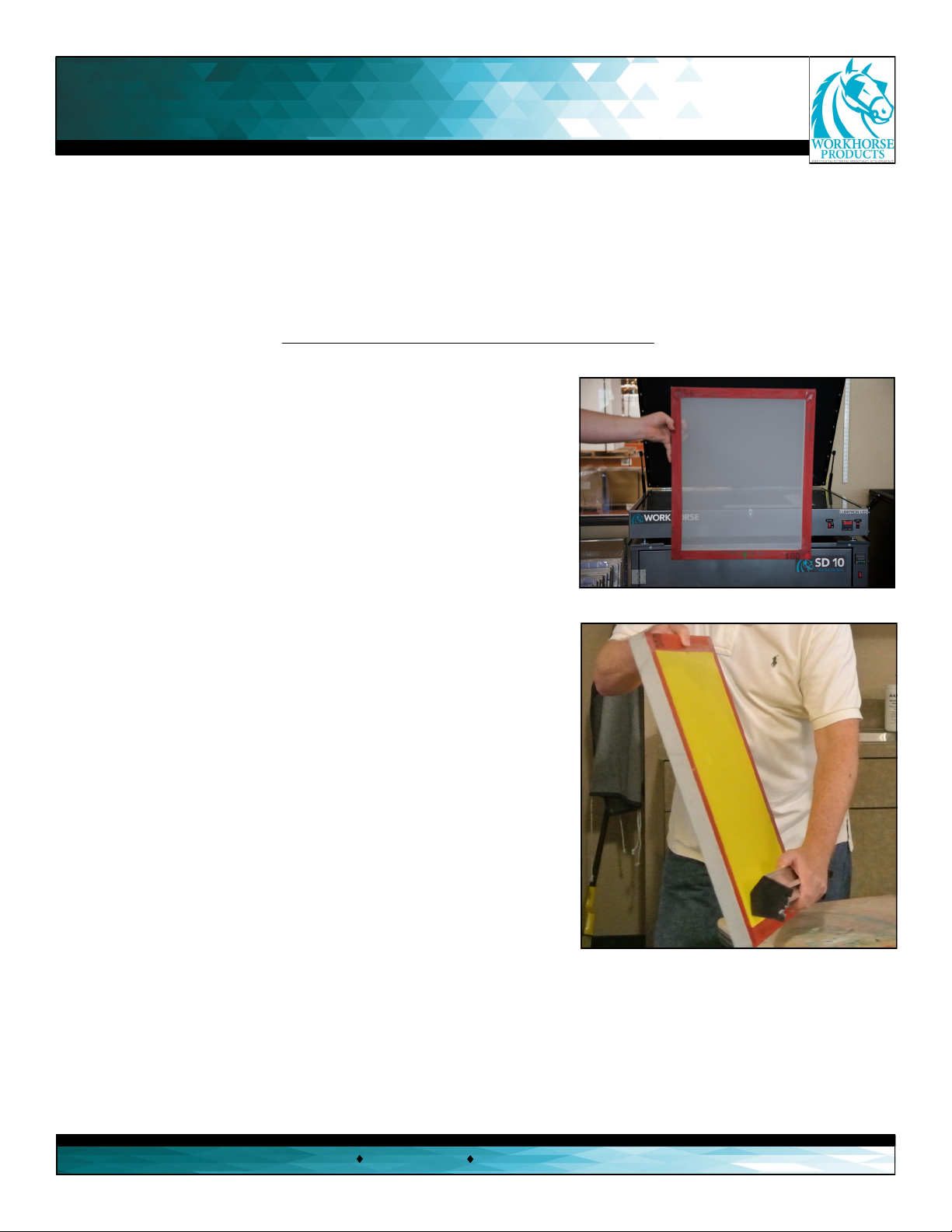
The screen needs to be dried in a dark locaon. Dry the
screen in a horizontal posion with the outside print side
facing down. This posioning is essenal to aid the
drawing emulsion to create a at and smooth surface. A
fan can be used to circulate the air around the screen
decrease the drying me. The normal drying me for a
properly coated screen can be anywhere from 30 –60
minutes. However, areas that have moisture in the air
will take exceedingly longer.
Step 4:
There is no standard exposure me because of all of the variables
involved. Use an exposure calculator to properly determine the
correct exposure me. Most emulsion manufactures have their
own exposure calculator, but they all relavely funcon in the
same manner.
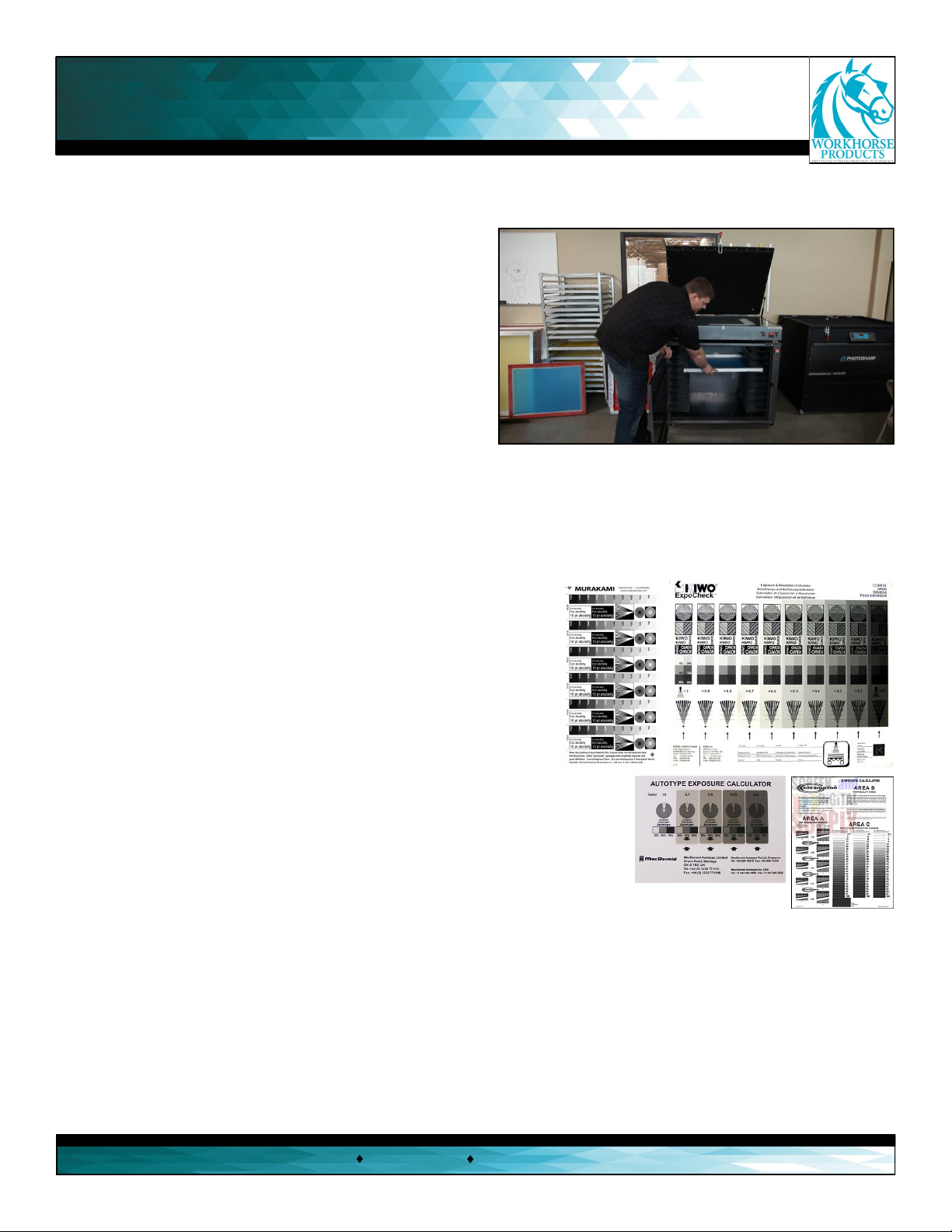
Exposure calculators are lm posives that have various degrees
of detailed lines that are covered with dierent factors. The
purpose is to expose the calculator onto a screen as a starng me and
each lter will have a factor number. Aer the screen is washed out,
observe which image is the hardest while containing the most detail
and mulply the factory number by the starng exposure me to get
the correct exposure me.
A Workhorse SD-10 drying cabinet will immensely speed up the drying process and eliminate the danger of
dust, which will guarantee high quality screens and increase producon speed.
For example, a screen is exposed for one minute with the calculator and the best image washed
out has a lter factor of .5 , so 1:00 x .5 = 30 seconds. To guarantee the best screens test every screen that
has a dierent variable like: dierent mesh count, dierent emulsion brand, and dierent coang technique.
It’s best to test for each season change. The seasons inuence temperature, humidity and moisture that will
aect the exposing of a screen.

Exposing a Screen
3730 E. Southern Avenue, Phoenix, AZ 85040 USA
800-778-8779 Workhorseproducts.com 10
Step 5:
Inspect the glass to make sure that it’s clean. Clean glass
makes a beer quality screen.
Step 6:
Aach the lm posive to the print side. The posive
should be posion so that from the squeegee side,
the posive is read le to right. It’s very helpful to
use a preregistraon system to make sure each piece
of lm is aached to the screen in proper relaon to
the other images.
Step 7:
Lay the frame on the glass with the lm side down
and the squeegee side up. Next, lay the rope from
inside the screen across the screen edges and in
front of the vacuum hole. The rope creates an escape
route for the air inside the frame, it also keeps the
vacuum port from sealing against the glass.
Step 8:
Close the vacuum lid and latch it into place with the red
latch/seal mechanism. First, turn the power buon on.
Second, hit the vacuum switch and allow the vacuum
blanket to complete and draw down around the frame.
Third, set the desired exposure me and then press the
mer switch, which will trigger the light and start the
mer countdown for the amount of me that was
previously set.

Exposing a Screen
3730 E. Southern Avenue, Phoenix, AZ 85040 USA
800-778-8779 Workhorseproducts.com 11
Step 9:
When the exposure me ends turn the vacuum
switch to the o posion. Release the latch handle
and very slowly li the lid to release the air. Opening
the lid slowly is very crical, because the screen
could potenally be pressurized to the top of the lid
and if lied too quickly it could fall and break the
glass.
Next, take the screen to be washed out in a sink to be
developed.
To increase the life lamp, Workhorse Products recommends leaving the PhotoSharp on to expose mulple
screens. Turning the PhotoSharp on and o for each exposure may shorten the lamp’s life.
Look through the glass top to see the light source, which contains the 1000 wa metal halide lamp. The
shuer on the light source opens during the exposure cycle and closes to prevent harmful UV exposure.
The vacuum pump is a true vacuum pump designed to evacuate the air between the vacuum blanket and
the screen frame quickly and eciently.
The dual receptacle in the corner powers the vacuum pump and the light source. These components are
controlled by the switches on the main control panel.

Disassembly of the Unit
3730 E. Southern Avenue, Phoenix, AZ 85040 USA
800-778-8779 Workhorseproducts.com 12
The Photosharp Exposure Unit is specically engineered to facilitate easy disassembly without the use of
special tools or equipment. Disassembly may be required to allow the Photosharp to pass through narrow
doorways.
1. Unscrew the two screws in the
top panel and remove it.
3. Unscrew the two screws in the
boom drawer and pull it out.
2. With the top panel detached
the glass can be removed. Push
the glass up from below. Pivot
the glass upward while making
sure the glass does not slide o
the track.
4. Once the drawer is removed,
disconnect the photo cell and the
electrical cord as shown. Rest the
wires on the corner brace where
the receptacle is located unl
needed.
5. Disconnect the vacuum line
from the tube that exits the rear of
the PhotoSharp and from the
ng on the vacuum blanket.
With the boom drawer removed,
disconnect the vacuum line and
the power cords for the light
source and vacuum pump.
6. Noce the row of bolts along the
lip inside the cabinet. Some bolts are
posioned with bolt heads facing up
and others are posioned with the
nuts facing up. Working from within,
remove only the bolt heads facing
up. The upper cabinet may now be
separated from the drawer cabinet.

Maintenance
3730 E. Southern Avenue, Phoenix, AZ 85040 USA
800-778-8779 Workhorseproducts.com 13
Cleaning the Glass
Disconnect the power before servicing the PhotoSharp.
To clean the under side of the glass, remove the two
screws located on either side of the front panel.
Remove the front panel and set it aside.
Using lint free rags or paper towel, spray the glass
cleaner directly on the towel and while reaching
through the front panel access hole clean the boom
surface on the glass.
Replacing the Bulbs
The 1000 wa metal halide lamp is a high energy lamp that will create a very even exposure across the print
area. This is a pin point light source that will result in sharp dened edges of the exposed design.
Extreme cauon must be taken when replacing the 1000 wa metal halide lamp. Always unplug the power
cord from the wall before aempng any maintenance or replacing the lamp.
The 1000 wa metal halide lamp outputs a high level of UV radiaon, which can cause eye and skin damage.
Never aempt to operate the PhotoSharp with the drawer or top open. The PhotoSharp exposure unit is
equipped with safety features that will prevent the lamp from illuminang when the drawer or top is open.
1. Always unplug the power cord from the wall before
aempng any maintenance or before replacing the
lamp.
Open the boom drawer by removing the two screws to
access the light source.
The light source will stay closed when the lamp is not
illuminated. The shuer will open when the exposure
cycle begins and will close to end the exposure cycle.
Never aempt to operate the PhotoSharp when the
drawer is open.

Maintenance
3730 E. Southern Avenue, Phoenix, AZ 85040 USA
800-778-8779 Workhorseproducts.com 14
Replacing the Bulbs (Connued)
2. Open the shuer. Fully opening the shuer will
allow the shuer to operate properly aer the
lamp has been replaces and power is reconnected
to the light source.
3. Locate the two wire leads supplying power to
the lamp.
4. Disconnect each lead from the
front and rear of the lamp as
shown.
5. Before reaaching the wire
leads use alcohol pad to clean the
lamp and reector panel. While
holding the lamp with a paper
towel or cloth to maintain
cleanliness, press the ends of the
lamp into the clips. Reconnect
the two wire leads.
Do not touch the lamp during installaon. Any contaminaon transferred to the lamp may cause premature failure.
6. Do not reposion the shuer
manually. The shuer will actuate
automacally when power is
restored to the PhotoSharp. Once
the lamp has been cleaned and
properly installed close the
boom drawer and fasten the two
screws

Replacing Vacuum Blanket
3730 E. Southern Avenue, Phoenix, AZ 85040 USA
800-778-8779 Workhorseproducts.com 15
Replacing the Vacuum Blanket
1. Close and latch the lid before replacing the
vacuum blanket. Remove the vacuum hose
from the vacuum hose nipple. Using a small
screw driver pry o the spring loaded cap to
remove the gas shock. Unbolt the hinges from
the rear.
Unlatch the top to remove the top frame and
vacuum blanket assembly.
2. Remove all of the screws from the blanket
retaining bracket. Then remove the frame to
replace the damaged blanket.
Posion the replacement vacuum blanket
over the frame, so that it droops naturally.
The vacuum blanket should not be stretched
ght. Reaach the blanket retaining bracket.
Replace the frame and blanket assembly onto
the PhotoSharp base. Align and reaach the
hinges.
3. Reaach the gas shocks by pushing the top
of the gas shock connector onto the pivot ball
and also by connecng the spring loaded cap.
Check for leaks before returning to normal
operaon.

Safety Features
3730 E. Southern Avenue, Phoenix, AZ 85040 USA
800-778-8779 Workhorseproducts.com 16
Magnec Safety Switch
The PhotoSharp is equipped with a magnec safety
switch that is located on the right hand side of the
exposure unit cabinet and lid. If the magnec safety
switch is open (lid up) the light will not operate.
When the lid is closed the magnec safety switch
will complete the circuit connecon and the light will
operate.
Shuer
If the lid is opened during the exposure cycle, the
shuer on the light source will automacally close to
protect the user from harmful UV rays.
Photo Cell
A yellow photo cell is located at the rear of the
PhotoSharp and monitors the light source. The photo
cell sense the light emied from the light source when
the shuer opens during the exposure cycle. If the
photo cell does not sense the lamp has illuminated, it
will countdown one second on the main mer and turn
the mer o.

Spare Parts List
3730 E. Southern Avenue, Phoenix, AZ 85040 USA
800-778-8779 Workhorseproducts.com 17
Electrical Specicaons
Part no. 11600B 115v 60hz 1100 was
Part no. 11601B 220v 50hz 1100 was (Euro only)
115VAC 230VAC
Descripon Part Number Part Number
Vacuum blanket 41 x 51 20501R
Exhaust Fan 31-76004 76005
Vacuum line 52-74014
Power cord 390752 390783
Casters 71000
Vacuum pump 115v 31-76051 31-76056
Photocell assembly 42036R
Timer assembly 30-1261
Vacuum on o switch 30-6227
Main power switch 30-3100-2
1000w metal halide bulb 390749
Gas shock 40-75021
Switch push buon 5543
Relay 30-1287
Vacuum body female 40-74015
Vacuum body male 40-74025
For more extensive parts and trouble shoong help with ANY Workhorse
Product please visit our on-line Parts store and
Support Center at:
hp://support.workhorseproducts.com/store/

Wiring Diagram
3730 E. Southern Avenue, Phoenix, AZ 85040 USA
800-778-8779 Workhorseproducts.com 18

Limited Warranty
3730 E. Southern Avenue, Phoenix, AZ 85040 USA
800-778-8779 Workhorseproducts.com 19
Although every eort has been made to provide accurate specicaons, Workhorse Products does not assume any liability
for damages, whether consequenal or incidental, that may result from the use or misuse of the indicated specicaons.
Workhorse Products requires the use of a licensed industrial electrician for the installaon of electrical service to equip-
ment requiring electrical power.
Workhorse Products reserves the right to alter specicaons in the manufacture of its products. It is understood and agreed
that Seller’s liability for any equipment whether liability in contract, in tort, under any warranty, in negligence, in strict liability
or otherwise shall not exceed the return of the amount of the purchase price paid by Buyer. Not withstanding the foregoing
provision, under no circumstances shall Seller be liable for special, indirect or consequenal damages. The price stated for the
equipment is a consideraon in liming Seller’s liability. No acon regardless of form, arising out of the transacons under
this Agreement may be brought by Buyer more than one (1) year aer the cause of acon has occurred. Our warranty is spec-
ied is exclusive and no other warranty, whether wrien or oral, is expressed or implied. Workhorse Products specically
disclaims the implied warranes of merchantability and tness for a parcular purpose. Equipment manufactured or sold by
Workhorse Products is warranted against defects in workmanship and materials for a period of one year from receipt by cus-
tomer. All warranes iniate from date of shipment to original customer. Replacement parts are covered for the term of the
equipment warranty period. Parts not under warranty are covered for thirty (30) days from receipt by customer. Any part
found by Workhorse Products to be defecve in material or workmanship within the stated warranty period will be replaced
or repaired at Workhorse’s opon without charge.
AFTER OBTAINING AN RMA# SEND RETURNED FREIGHT PREPAID TO 3730 E. Southern Avenue, PHOENIX, AZ 85040 USA.
Wrien authorizaon must be obtained from Workhorse before any part will be accepted. Replacement parts are sent out
freight collect.
Parts sent out prior to receiving defecve require a credit card hold for cost plus freight. Upon return of defecve part, if it
is deemed that the part was not damaged by customer but failed, the cost of the replacement part will be refunded.
This warranty does not extend to expendable parts such as lters, fuses, elements and brushes. Workhorse does not war-
rant failure of parts or components resulng from misuse or lack of proper maintenance. Installaon, inspecon, and
Table of contents
Other Workhorse Printer manuals