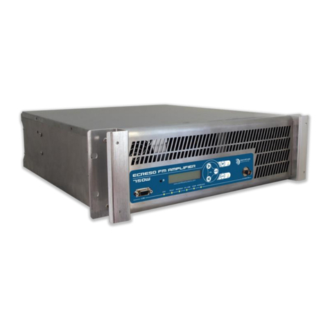
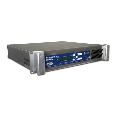
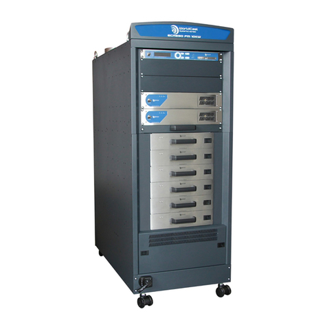
Worldcast Systems SOLAR FM User manual

SOLAR FM User Manual v.1.95.x –11/2018
Page 2
Head Office : Parc d’activites Kennedy - 20, avenue Neil Armstrong –33700 Bordeaux-Merignac (France)
Tel +33 (0)5 57 928 928 –Fax +33 (0)5 57 928 929 –contact@worldcastsystems.com –www.worldcastsystems.com
CONTENT
1. INTRODUCTION.........................................................................................................................4
1.1. About WorldCast Systems ............................................................................................................ 4
1.2. About the SOLAR FM .................................................................................................................... 5
1.3. Safety Precautions ........................................................................................................................ 5
2. RECOMMENDATIONS ................................................................................................................7
2.1. Storage.......................................................................................................................................... 7
2.2. Installation .................................................................................................................................... 7
2.2.1. SOLAR FM bindings ................................................................................................................ 7
2.2.2. Electrical recommendations .................................................................................................. 7
2.2.3. Solar recommendations......................................................................................................... 8
2.2.4. RF recommendation............................................................................................................... 9
3. SPECIFICATIONS ......................................................................................................................10
4. SYSTEM PRESENTATION...........................................................................................................12
4.1. Accessories.................................................................................................................................. 12
4.2. System synoptic .......................................................................................................................... 13
4.3. Transmitter casing ...................................................................................................................... 14
4.3.1. Rear view.............................................................................................................................. 15
4.4. Connectors.................................................................................................................................. 16
4.4.1. Battery management module.............................................................................................. 16
4.4.2. Connectors ........................................................................................................................... 16
4.4.3. Connectors’ specifications ................................................................................................... 17
4.5. Audio signal sources ................................................................................................................... 19
4.5.1. Satellite receiver .................................................................................................................. 19
4.5.2. FM receiver .......................................................................................................................... 20
4.5.3. Analog inputs (L&R) and digital input (AES)......................................................................... 20
4.6. Power supplies............................................................................................................................ 20
4.7. FM transmitter............................................................................................................................ 21
4.8. Control unit –CPU ...................................................................................................................... 22
4.9. WiFi module................................................................................................................................ 22
5. QUICK START...........................................................................................................................23
5.1. Unpacking ................................................................................................................................... 23
5.2. Transmitter bench test (optional)............................................................................................... 24
5.2.1. Cable connection.................................................................................................................. 25

SOLAR FM User Manual v.1.95.x –11/2018
Page 3
Head Office : Parc d’activites Kennedy - 20, avenue Neil Armstrong –33700 Bordeaux-Merignac (France)
Tel +33 (0)5 57 928 928 –Fax +33 (0)5 57 928 929 –contact@worldcastsystems.com –www.worldcastsystems.com
5.2.2. SOLAR FM configuration using the application.................................................................... 25
5.2.3. Checking good working order.............................................................................................. 27
5.3. Powering up the transmitter ...................................................................................................... 28
5.4. Connections ................................................................................................................................ 29
5.5. Installing the SOLAR FM.............................................................................................................. 30
5.5.1. Connecting the solar panels to the transmitter................................................................... 30
5.5.2. Fastening the SOLAR FM...................................................................................................... 32
6. THE MOBILE APPLICATION.......................................................................................................34
6.1. Prerequisite and connection....................................................................................................... 34
6.2. Application overview .................................................................................................................. 35
6.3. Maintenance............................................................................................................................... 39
6.3.1. Transmitter........................................................................................................................... 39
6.3.2. Satellite................................................................................................................................. 40
6.3.3. FM Receiver.......................................................................................................................... 41
6.3.4. Audio inputs ......................................................................................................................... 41
6.3.5. Power supply........................................................................................................................ 42
6.4. Configuration .............................................................................................................................. 42
6.4.1. General configuration .......................................................................................................... 43
6.4.2. Transmitter configuration.................................................................................................... 44
6.4.3. Satellite configuration.......................................................................................................... 45
6.4.4. FM receiver configuration.................................................................................................... 46
6.4.5. Preset configuration............................................................................................................. 46
6.4.6. Scheduler configuration....................................................................................................... 47
6.5. System......................................................................................................................................... 48
6.5.1. Product................................................................................................................................. 49
6.5.2. Date and time....................................................................................................................... 49
6.5.3. Communication.................................................................................................................... 50
6.5.4. Support................................................................................................................................. 50
6.5.5. Terminal ............................................................................................................................... 51
6.5.6. Event logs ............................................................................................................................. 51
6.5.7. Software upgrades ............................................................................................................... 52
7. CONFIGURATION COMMANDS.................................................................................................53
7.1. Accessing the configuration console .......................................................................................... 53
7.2. Syntax.......................................................................................................................................... 53
7.3. List of commands........................................................................................................................ 54
FOR MORE INFORMATION...........................................................................................................60

SOLAR FM User Manual v.1.95.x –11/2018
Page 4
Head Office : Parc d’activites Kennedy - 20, avenue Neil Armstrong –33700 Bordeaux-Merignac (France)
Tel +33 (0)5 57 928 928 –Fax +33 (0)5 57 928 929 –contact@worldcastsystems.com –www.worldcastsystems.com
1. INTRODUCTION
1.1. About WorldCast Systems
WorldCast Systems is a highly respected provider of professional, reliable and innovative solutions to the
Radio & TV industry worldwide.
Encompassing the industry-leading brands of APT, Ecreso & Audemat, WorldCast Systems offers high-
performing broadcast systems including audio codecs, FM transmitters and RF signal monitoring
designed to meet the needs of both large international broadcast networks and small private stations
alike. WorldCast Systems’ products are deployed throughout the networks of many major public and
commercial broadcasters such as the BBC, ARD, the EBU, RTE, TDF, RNE, Teracom, RAI, ORF and Clear
Channel Radio.
•APT codecs deliver audio over IP, T1, ISDN & Leased Lines. Our award-winning SureStream
technology enables high quality audio transport over cost-effective IP links.
•Ecreso offers highly efficient FM transmitters with extensive inbuilt functionality, highly
competitive Total Cost of Ownership and an industry-leading 10 year warranty.
•Audemat provides a range of professional monitoring and measurement tools for Radio & TV,
complemented by an extensive range of remote control systems for management, configuration
and monitoring of broadcast networks.
Three core values have shaped the growth and direction of WorldCast Systems
1) Product innovation:
WorldCast Systems places a key emphasis on Research & Development and its innovative
approach has been repeatedly recognized by the industry. Our products have been selected to
receive awards for innovation at consecutive NAB Shows for over 13 years.
2) Customer satisfaction:
WorldCast Systems is dedicated to ensuring the best quality, value and service for its customers
and has achieved IS0 9001 certification.
3) Sustainable Development:
WorldCast Systems is committed to sustainable development and demonstrates this
commitment in several ways: all new products are developed in keeping with an eco-design
philosophy and built within a low energy consumption factory and the company has also
established Proximité Carbone, a foundation to enable reforestation.
Headquartered in Bordeaux-Merignac, France, WorldCast Systems employs nearly 100 people worldwide
with an R&D center in Northern Ireland and sales offices in the UK, Germany, India and the US. A global
distributor network works together with our international sales and support staff to offer local assistance
to our international customer base.

SOLAR FM User Manual v.1.95.x –11/2018
Page 5
Head Office : Parc d’activites Kennedy - 20, avenue Neil Armstrong –33700 Bordeaux-Merignac (France)
Tel +33 (0)5 57 928 928 –Fax +33 (0)5 57 928 929 –contact@worldcastsystems.com –www.worldcastsystems.com
1.2. About the SOLAR FM
The SOLAR FM is a unique FM transmission solution designed to operate in isolated areas with limited
electrical infrastructure, covering up to 10 km areas.
Capable of receiving audio from FM and satellite as well as analog and/or AES inputs, the system comes
complete with appropriate antennas and a dedicated smartphone application for control.
The standard system utilizes solar power with AC power back-up and wind power capability is available
as an option.
Designed to operate in harsh environmental conditions, the SOLAR FM can be easily deployed in
mountainous areas, forests and deserts. Once securely fastened to a mast, the user simply needs to
connect the energy input and audio sources and they are ready to broadcast!
1.3. Safety Precautions
This equipment complies with international mechanical and electrical standards. To maintain this
compliance, as well as to ensure proper and safe working conditions and avoid electrical shocks and fire
hazards, you must comply with the following recommendations:
The device should only be utilized in the conditions described in the user manual.
The device is designed for industrial usage and must only be operated by qualified personnel.
The device may be heavy; it must be lifted and handled with care, specifically during unpacking
and set up.
Electrical precautions
Unplug from mains outlet before any intervention.
Any maintenance, adjustment or repair must be carried out by personnel specifically trained by
WorldCast Systems.
Before switching on the device, make sure the nominal voltage specified on the device matches
the mains nominal voltage.
The device should only be operated on a stable electrical network. If the electrical network is not
stable, a power conditioner, such as a UPS, must be used
The device must only be used with a plug that incorporates a protective ground contact.
To avoid any risk of electrocution, the protective earthing conductor must not be cut,
intentionally or accidentally, either on the device or on the power cord.
High quality shielded cables are mandatory.
Environmental precautions
It is necessary to verify that environmental conditions comply with those recommended in the
manual.
Nothing must obstruct the ventilation.

SOLAR FM User Manual v.1.95.x –11/2018
Page 6
Head Office : Parc d’activites Kennedy - 20, avenue Neil Armstrong –33700 Bordeaux-Merignac (France)
Tel +33 (0)5 57 928 928 –Fax +33 (0)5 57 928 929 –contact@worldcastsystems.com –www.worldcastsystems.com
To avoid any electromagnetic interference, the device must only be used when it is closed,
installed in a cabinet and connected to the earth as per the instructions.
The device should not be exposed to dripping or splashing and no objects filled with liquids, such
as coffee cups, should be placed on the equipment.
Connectors may be hot on high power units.
Precautions regarding the lithium battery and the NiMH battery
This device includes a lithium battery and an NiMH battery.
Do not puncture the batteries
Do not throw the batteries in fire
Do not immerse the batteries in water
Do not throw away the used batteries, recycle them instead. You may send them back to us if
needed.
Lithium battery
If the battery is not correctly replaced, there is a risk of explosion.
Only replace it with a battery of the same type. Contact us before attempting to use another type
NiMH battery
If the battery is not correctly replaced, it may damage the equipment.
Only replace it with a battery of the same type and after having contacted the WorldCast Systems
support team.
Practices to follow to extend the life of the battery:
When not in use, store in a place with a stable ambient temperature between +10°C et +25°C.
When stored, unplug the battery from the equipment.
Make sure the battery is never completely empty when stored. We recommend charging it once
a month while in storage.
If these precautions are not followed, the guarantee will be void.

SOLAR FM User Manual v.1.95.x –11/2018
Page 7
Head Office : Parc d’activites Kennedy - 20, avenue Neil Armstrong –33700 Bordeaux-Merignac (France)
Tel +33 (0)5 57 928 928 –Fax +33 (0)5 57 928 929 –contact@worldcastsystems.com –www.worldcastsystems.com
2. RECOMMENDATIONS
2.1. Storage
!Storing the SOLAR FM for a long period may lead to a complete discharge of the battery and to its
deterioration. If a long storage time is required, reload the battery using solar panels or a
stabilized lab power supply before it is discharged.
The frequency for recharging depends on the storage temperature:
Every 250 days if stored between 20 and 30°C
Every 100 days if stored between 10 et 20°C
Every 30 days if stored between 5 and 10°C or between 30 and 35°C
2.2. Installation
2.2.1. SOLAR FM bindings
The SOLAR FM is a system which operates outdoors.
We recommend you set it up on a pole (or pylon) with the supplied frame.
!We recommend you do not set it at the bottom of the pole to limit the risks if defacing, theft…
On flat ground, WorldCast Systems recommends installing the transmission antenna about 10 meter high
in order to best cover the area. Other elements can then be installed at a lower height and connected
using supplied cables.
For urban installation, the transmitter will be set higher than the highest potential obstacles (trees,
buildings,…)
2.2.2. Electrical recommendations
!Before any handling of the system, disconnect the battery and the mains from the transmitter.
!When installing, make sure to connect all elements before starting up.
Starting the unit before all cabling operations are completed could lead to damage of the various
stages of the system.

SOLAR FM User Manual v.1.95.x –11/2018
Page 8
Head Office : Parc d’activites Kennedy - 20, avenue Neil Armstrong –33700 Bordeaux-Merignac (France)
Tel +33 (0)5 57 928 928 –Fax +33 (0)5 57 928 929 –contact@worldcastsystems.com –www.worldcastsystems.com
2.2.3. Solar recommendations
2.2.3.1. Installing the solar panels
WorldCast Systems supplies solar panels required to operate the SOLAR FM. You may however use other
panels.
Be careful to not select oversized solar panels which could be detrimental to the proper working of the
transmitter. Use solar panels with specifications matching those of panels supplied by WorldCast
Systems (see chapter 3).
Depending on the installation zone (longitude, latitude), it is essential to correctly position the solar
panels to insure the best performance.
Two parameters need to be checked:
The orientation
The inclination
The best orientation depends on the latitude:
Installation north of the Equator (Northern Hemisphere): panels must be oriented towards the
south.
Installation south of the Equator (Southern Hemisphere): panels must be oriented towards the
north.
Once the orientation is set, the inclination of the solar panels must be set in order to obtain the best
possible efficiency.
For optimal efficiency, panels must be perpendicular to sun rays when the sun is at its highest point.
To find the right position according to your location, a sun position calculator is available at
http://www.solartopo.com/solar-orbit.htm..

SOLAR FM User Manual v.1.95.x –11/2018
Page 9
Head Office : Parc d’activites Kennedy - 20, avenue Neil Armstrong –33700 Bordeaux-Merignac (France)
Tel +33 (0)5 57 928 928 –Fax +33 (0)5 57 928 929 –contact@worldcastsystems.com –www.worldcastsystems.com
2.2.3.2. System maintenance
As an outdoor system, the SOLAR FM requires heavier maintenance than an indoor system.
It is therefore essential to:
Clean the solar panels at least once a year to insure their efficiency,
Change the NiMH battery every three years to maintain the initial transmission potential.
!Warning: the SOLAR FM includes a battery management system designed to optimize the battery
charge and discharge.
To replace it with a battery not approved by WorldCast Systems may lead to a dysfunction of the
unit which would not be covered by the warranty.
!Never allow the NiMH battery to be completely empty.
2.2.4. RF recommendation
The SOLAR FM includes reception and transmission antennas.
Make sure each is properly installed. Please refer to the installation documentation for each antenna.

SOLAR FM User Manual v.1.95.x –11/2018
Page 10
Head Office : Parc d’activites Kennedy - 20, avenue Neil Armstrong –33700 Bordeaux-Merignac (France)
Tel +33 (0)5 57 928 928 –Fax +33 (0)5 57 928 929 –contact@worldcastsystems.com –www.worldcastsystems.com
3. SPECIFICATIONS
FM transmitter
Frequency range: 87.5 - 108 MHz adjustable in 10 kHz increments
Power range: 2 - 25 W in 1 W increments
Configurable level:
-0 to 90 kHz total MPX deviation
-0 to 90 kHz AF deviation
-0 to 9.9 kHz 19 kH PILOT deviation
Configurable preemphasis: 50 or 75 µs
Mono or Stereo mode
Direct output power and reflected output power readings
S/N: > 60 dB RMS Mono
S/N: > 50 dB RMS Stereo
THD+N Distorsion: typical 0.3%
L/R stereo separation: 40 dB
* Readings conditions: F = 98 MHz / 75 kHz MPX dev / 1 kHz AF Sine
Satellite receiver
Frequency range: 950-2150 MHz
Compatible with DVB-S & DVB-S2 standards (auto selection)
Demodulation: QPSK, 8PSK (auto selection)
User settable LNB input
FM receiver
Frequency range: 87.5 - 108 MHz
S/N: >55 dB (Mono & Stereo)
THD+N Distorsion: typical 0.3%
L/R stereo separation: 40 dB
* Readings conditions: F = 98 MHz / 75 kHz MPX dev / 1 kHz AF Sine
Audio inputs
2 analog inputs (6-pin connectors)
Input impedance: >10 kΩ
Input level: nominal +12 dBu
1 AES input (4-pin connectors)

SOLAR FM User Manual v.1.95.x –11/2018
Page 11
Head Office : Parc d’activites Kennedy - 20, avenue Neil Armstrong –33700 Bordeaux-Merignac (France)
Tel +33 (0)5 57 928 928 –Fax +33 (0)5 57 928 929 –contact@worldcastsystems.com –www.worldcastsystems.com
Input impedance: 110 kΩ
Sample format 24 bits
Sampling frequency: 48 kHz
Solar panels and battery
2 solar panels
Voltage: typical 36 VDC / 44 VDC max
Power: typical 100 W / 140 W max
Max currant: 5 A
1 NiMH battery (240 Wh)
1 battery management system
VAC mains input
Input voltage: 100 to 300 V AC
Frequency : 47 to 63 Hz
Max power consumption: 60 W
Communication
WiFi connectivity (802.11 b/g/n)
Local port: RS232c –adjustable 115200, 9600, 1200 bps baudrate
Configuration with mobile application:
ANDROID (version 5.0 Lollipop minimum)
iOS (version 10 minimum) –available 2018
Physical specifications
Transmitter
Dimensions (L x l x H)
Weight
300 mm x 200 mm x 600 mm:
~20 kg
Solar panel (x2)
Dimensions (L x l x H)
Weight
805 mm x 1365 mm x 35 mm
~12,5 kg
2nd battery
Dimensions (L x l x H)
Weight
150 mm x 150 mm x 360 mm
~8 kg
Operating temperature
-20° - 60°C
Humidity
5 - 95% non-condensing relative humidity
Miscellaneous
Watertightness: IP66 certification

SOLAR FM User Manual v.1.95.x –11/2018
Page 12
Head Office : Parc d’activites Kennedy - 20, avenue Neil Armstrong –33700 Bordeaux-Merignac (France)
Tel +33 (0)5 57 928 928 –Fax +33 (0)5 57 928 929 –contact@worldcastsystems.com –www.worldcastsystems.com
4. SYSTEM PRESENTATION
4.1. Accessories
The following accessories are supplied with the SOLAR FM:
SOLAR FM box:
o1 transmitter + connected RF output cable
o1 binding frame + 2 sets of claws and nuts
o1 radome
o1 cable for photovoltaic panels (SP02285)
o1 test audio cable (CA01050)
o1 mains cable (CA01039)
oZip ties
And depending on order:
o2 photovoltaic panels + bindings
o1 FM transmission antenna
o1 FM reception antenna + cable (CA01044)
o1 satellite reception antenna + cable (SP02355)
o1 smartphone
o1 audio cable (CA01043)
o1 AES cable (CA01042)
o2nd battery

SOLAR FM User Manual v.1.95.x –11/2018
Page 13
Head Office : Parc d’activites Kennedy - 20, avenue Neil Armstrong –33700 Bordeaux-Merignac (France)
Tel +33 (0)5 57 928 928 –Fax +33 (0)5 57 928 929 –contact@worldcastsystems.com –www.worldcastsystems.com
4.2. System synoptic
Overview of the modules and their interconnections:
Control
unit
Pilote
Ampli-
fier
BMS
Solar
panels
FM output
(Tx)
FM Rx
Satellite
Rx
Analog
input
AES input
AC input
Mobile
application
WiFi
module
AES
L+R
DVB-S
DVB-S2
FM
DC input
(option)
Battery

SOLAR FM User Manual v.1.95.x –11/2018
Page 14
Head Office : Parc d’activites Kennedy - 20, avenue Neil Armstrong –33700 Bordeaux-Merignac (France)
Tel +33 (0)5 57 928 928 –Fax +33 (0)5 57 928 929 –contact@worldcastsystems.com –www.worldcastsystems.com
4.3. Transmitter casing
Inside view:
Satellite
board
Main board: includes
3 power supplies +
FM receiver
Connectors
Battery
Module
WiFi
CPU

SOLAR FM User Manual v.1.95.x –11/2018
Page 15
Head Office : Parc d’activites Kennedy - 20, avenue Neil Armstrong –33700 Bordeaux-Merignac (France)
Tel +33 (0)5 57 928 928 –Fax +33 (0)5 57 928 929 –contact@worldcastsystems.com –www.worldcastsystems.com
4.3.1. Rear view
RF Module
Battery
management
module
Mains power
supply
Connectors

SOLAR FM User Manual v.1.95.x –11/2018
Page 16
Head Office : Parc d’activites Kennedy - 20, avenue Neil Armstrong –33700 Bordeaux-Merignac (France)
Tel +33 (0)5 57 928 928 –Fax +33 (0)5 57 928 929 –contact@worldcastsystems.com –www.worldcastsystems.com
4.4. Connectors
4.4.1. Battery management module
4.4.2. Connectors
View of the SOLAR FM connectors
Protective watertight caps are set on connectors for transport. Only remove caps on connectors you
will use.
Do not unscrew fixed connectors as it may compromise the watertight integrity of the product (IP66).
If the product is no longer waterproof, the warranty will be void.
Connection to the
solar panels
Connection to
the transmitter
Connection
to the battery
Satellite input
FM input
FM output
BMS control and
Battery input
100-300 V
mains input
RS232c terminal link
and Local button
Digital audio
input
DC power input
L&R analog
audio input

SOLAR FM User Manual v.1.95.x –11/2018
Page 17
Head Office : Parc d’activites Kennedy - 20, avenue Neil Armstrong –33700 Bordeaux-Merignac (France)
Tel +33 (0)5 57 928 928 –Fax +33 (0)5 57 928 929 –contact@worldcastsystems.com –www.worldcastsystems.com
4.4.3. Connectors’specifications
Power connectors
230 VAC mains input connector
P = Phase
N = Neutral
T = Earth
Auxiliary photovoltaic power input connector (DC)
Note: This connector must be linked to a dedicated photovoltaic
power unit. An adapted plug is supplied with the photovoltaic
panels supplied by WorldCast Systems.
Audio connectors
Analog audio input connector (AF)
Note: the inputs are balanced. To have an unbalanced
input, connect the Audio L- pin and the Audio L GND pin
together and the Audio R- pin and the Audio R GND pin
together.
GND BMS
18 AWG
+V BMS
18 AWG
CAN+
CAN-
GND CAN
3-pin connector
Front view
6-pin connector
Front view
5-pin connector
Front view

SOLAR FM User Manual v.1.95.x –11/2018
Page 18
Head Office : Parc d’activites Kennedy - 20, avenue Neil Armstrong –33700 Bordeaux-Merignac (France)
Tel +33 (0)5 57 928 928 –Fax +33 (0)5 57 928 929 –contact@worldcastsystems.com –www.worldcastsystems.com
Digital audio connector (AES)
Note: Input impedance is greater than 110 Ω, it is balanced via
transformer.
RF connectors
Satellite: screw N connector (SAT).
FM retransmitter’s RF input: screw N connector (FM IN).
Transmitter’s RF output: N connector which terminates a 4 m cable directly connected on the amplifier
board (FM OUT)
RS232c terminal link and local button connector (LOC)
GND RS232
TX RS232
RX RS232
GND LOCAL button
LOCAL button positive potential
5-pin connector
Front view
18 AWG
LOCAL SW
18 AWG
LOCAL SW
TX RS232c
RX
RS232
GND RS232
4-pin connector
Front view

SOLAR FM User Manual v.1.95.x –11/2018
Page 19
Head Office : Parc d’activites Kennedy - 20, avenue Neil Armstrong –33700 Bordeaux-Merignac (France)
Tel +33 (0)5 57 928 928 –Fax +33 (0)5 57 928 929 –contact@worldcastsystems.com –www.worldcastsystems.com
4.5. Audio signal sources
The SOLAR FM can use four different signal sources:
Satellite receiver
FM receiver
Analog inputs (L&R)
Digital input (AES)
Their configuration is managed from the mobile application available on the smartphone.
4.5.1. Satellite receiver
The satellite receiver allows retransmission of an unencrypted satellite
program with no additional equipment.
Integrated on a daughter board, the receiver demodulates the MPEG stream
encapsulated in the DVB-S or DVB-S2 signal and transmits it the FM driver
input in audio format.
To connect to the satellite antenna, an F connector is present on the satellite
receiver.
AUDIO
Outputs
DVB-S
Demodulator
MPEG
decoder
SAT dish and LNB
FM DRIVER
SATELLITE RECEIVER
Satellite reception antenna

SOLAR FM User Manual v.1.95.x –11/2018
Page 20
Head Office : Parc d’activites Kennedy - 20, avenue Neil Armstrong –33700 Bordeaux-Merignac (France)
Tel +33 (0)5 57 928 928 –Fax +33 (0)5 57 928 929 –contact@worldcastsystems.com –www.worldcastsystems.com
4.5.2. FM receiver
The FM receiver allows retransmission of a radio program received by
the SOLAR FM.
Integrated on the system’s main board, the receiver demodulates the
FM signal of the set frequency and transmit an audio stream to the
FM driver.
To connect to the FM antenna, an N connector is present on the FM
receiver.
4.5.3. Analog inputs (L&R) and digital input (AES)
Audio inputs supply the transmitter with a local audio stream. It can be analog (Left and Right) or digital
(AES).
Two dedicated connectors are available on the SOLAR FM:
1 watertight 6-pin connector for L and R analog inputs
1 watertight 4-pin connector for the AES input
4.6. Power supplies
The SOLAR FM accepts three power supplies sources:
AC with an input voltage from 100 to 300 VAC. A dedicated connector is available on the
transmitter to connect to the mains.
DC used by the solar system.
The solar system includes:
oa NiMH battery, when 100% charged and without being simultaneously recharged, the
battery offers 5 hours of operation
oa battery management system
otwo 80 W solar panels, connected in series (when supplied by WorldCast Systems).
This system can supply up to 12 hours of autonomy per day to the transmitter.
AUDIO
Outputs
FM
demodulator
FM reception
antenna
FM DRIVER
FM RECEIVER
FM reception antenna
Other manuals for SOLAR FM
1
Table of contents
Other Worldcast Systems Transmitter manuals