7
Additional safety points for your
jigsaw
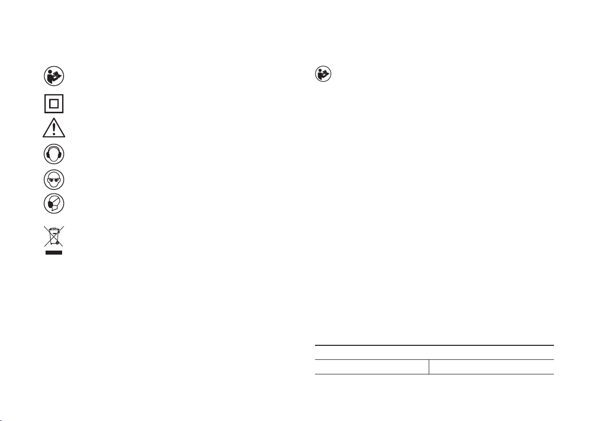
Always wear a dust mask.
Hold power tool by insulated gripping surfaces, when
performing an operation where the cutting accessory may
contact hidden wiring or its own cord. Cutting accessory
contacting a “live” wire may make exposed metal parts of the power
tool “live” and could give the operator an electric shock.
Use clamps or another practical way to secure and support
the workpiece to a stable platform. Holding the work by hand or
against your body leaves it unstable and may lead to loss of control.
Always wear safety glasses or eye shields when using the jig
saw. Everyday eyeglasses have only impact-resistant lenses; they are
NOT safety glasses. Following this rule will reduce the risk of serious
personal injury.
Always wear hearing protection during extended periods of
operation. Following this rule will reduce the risk of serious personal
injury.
Keep your hands away from cutting area. Do not reach under the
material being cut because the nearness of the blade to your hand is
hidden from your sight.
Do not use dull or damaged blades. Bent blades can break easily,
or cause kickback.
Remove the plug from the socket before carrying out any adjustment,
servicing or maintenance.
Fully unwind cable drum extensions to avoid potential overheating.
When an extension cable is required you must ensure it has the
correct ampere rating for your power tool and is in a safe electrical
condition.
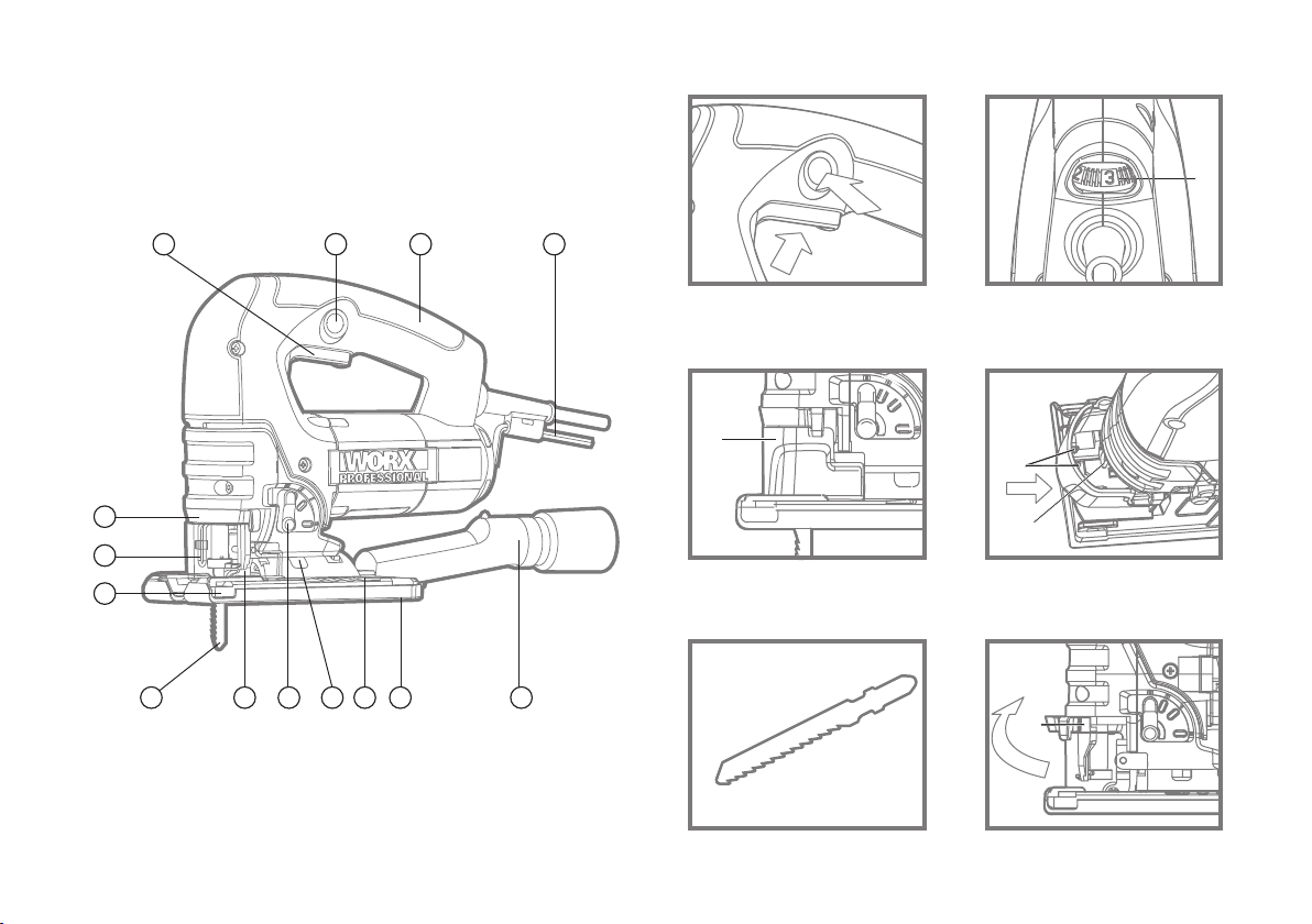
11
12
13
14
15
16
17
18
19
20
•
•
•
•
•
Ensure your mains supply voltage is the same as indicated on the
rating plate.
Your tool is double insulated for additional protection against a
possible electrical insulation failure within the tool.
Always check walls, floors and ceilings to avoid hidden power cables
and pipes.
After long working period, external metal parts and accessories could
be hot.
Only withdraw the blade from the cut when the blade has been
stopped moving.
The pivoting blade foot must be held firmly against the material being
cut to reduce saw vibration, blade jumping and blade breakage.
Before cutting, check the cutting line is free of nails, screws, etc.
If possible, ensure the work-piece is firmly clamped to prevent
movement.
Never stop the cutting blade by applying side pressure to the blade.
Your Jigsaw is a hand held tools, do not clamp your Jigsaw.
Warning: Some dust particles created by power sawing,
contain chemicals known to cause cancer, birth defects or
other reproductive harm. Some examples of these chemicals
are:
Lead from lead-based paints.
Crystalline silica from bricks and cement and other masonry products.
Arsenic and chromium from chemically treated lumber.
Your risk from these exposures varies, depending upon how
often you do this type of work. To reduce your exposure to these
chemicals:
Work in a well-ventilated area.
Work with approved safety equipment, such as those dust masks
that are specially designed to filter microscopic particles.
1
2
3
4
5
6
7
8
9
10