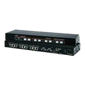
WTI RAB-14A User manual

WTI Part No. 12057
Rev. B
RAB-14A
A/B Switching System
Preliminary Draft
February 1997
User's Guide

5 Sterling ·Irvine ·California 92618-2517
(949) 586-9950 ·Toll Free: 1-800-854-7226
Fax: (949) 583-9514 ·http://www.wti.com

Table of Contents
1. Introduction ..............................................1-1
2. Unit Description ..........................................2-1
2.1. The Control Module......................................2-1
2.1.1. Control Module Front Panel ........................2-1
2.1.2. Control Module Back Panel.........................2-2
2.2. Switch Modules .........................................2-3
3. Installation ...............................................3-1
3.1. Control Module DIP Switches .............................3-1
3.1.1. Bank Number (Sw1 - Sw4).........................3-1
3.1.2. Baud Rate Selection (Sw5 and Sw6).................3-2
3.1.3. Parity Selection (Sw7).............................3-2
3.1.4. Duplex Selection (Sw8) ...........................3-2
3.1.5. Master / Satellite Bank Selection (Sw9) .............3-2
3.1.6. Remote Switch Selection (Sw10) ...................3-2
3.2. Switch Module Jumpers ..................................3-3
3.3. Control Module Jumper...................................3-4
3.4. Cable Connection ........................................3-4
3.5. Connecting Multiple RAB-14A Banks (Daisy Chaining) ......3-4
3.6. Quick Start / System Overview ............................3-6
4. Selecting Switching Methods ...............................4-1
4.1. Local Switch Control.....................................4-1
4.2. Gang Switch Control .....................................4-2
4.3. Local Signal Control .....................................4-3
4.4. ASCII Code Control......................................4-4
5. Operation; ASCII Code Control............................5-1
5.1. Command Syntax ........................................5-1
5.2. Switching A/B Channels ..................................5-2
5.3. Display Switch Status ....................................5-3
5.4. Test Switch Modules .....................................5-4
i
Appendices
A. Interface Descriptions ..................................Apx-1
A.1. Control Module .......................................Apx-1
A.1.1. Command Port .................................Apx-1
A.1.2. Remote Switch Port .............................Apx-1
A.2. Switch Module........................................Apx-2
A.2.1. Ports “A” and “B” (DTE) ........................Apx-3
A.2.2. Common Port (DTE or DCE) .....................Apx-3
B. Specifications ..........................................Apx-4
C. Customer Service.......................................Apx-4
List of Figures
2.1. Control Module Front Panel ...................................2-1
2.2. Control Module Back Panel ...................................2-2
2.3. Switch Module Front Panel ...................................2-3
3.1. Switch Module Jumpers ......................................3-3
5.1. The Status Screen (14 Banks Shown) ...........................5-3
5.2. The Test Screen (14 Banks Shown).............................5-4
A.1. Command Port ............................................Apx-1
A.2. The Remote Switch Port ...................................Apx-1
A.3. Switch Module Block Diagram..............................Apx-2
ii

1. Introduction
The RAB-14A is a versatile A/B switching system, designed for
applications that require routing of RS232 lines between a
common port and “A” and “B” ports. Modular A/B switches
toggle seven RS232 pins between “A” and “B” channels. Up to
fourteen RS232 lines and corresponding A/B channels can be
controlled by each RAB-14A rack unit.
A convenient modular design allows the RAB-14A to expand when
your application requires more than fourteen RS232 lines. Up to
fourteen RAB-14A frame units can be daisy-chained to provide a
maximum of 196 switches.
Several different switching methods are offered. A/B channel
selection can be controlled by manual switches, by ASCII Codes
sent from a PC or terminal, or can be switched automatically based
on a high or low signal level.
Applications
·Remote Routing of RS232 Lines
·Switch to “Out-of-Service” or “Off-Line” Condition
·Active or Fallback Gang Switching
·Disaster Recovery Switching
Features
·Mechanical Contacts for Analog and Digital Switching
·Independent RS232 Command Port
1-1

Typographic Conventions
Throughout this manual, typefaces and characters have been used
to denote the following:
^(e.g. ^A) Indicates a key combination used to invoke a
command. For example, the text “^A”
(Control A) indicates that the [Ctrl] key and
the [A] key must be pressed simultaneously.
COURIER FONT Indicates characters typed on the keyboard.
For example, ^AS or ^A00 00 B.
[Bold Font] Text set in bold face and enclosed in
square brackets, indicates a specific key.
For example, [Enter] or [Esc].
1-2
RAB-14A User’s Guide

2. Unit Description
The RAB-14A consists of a frame unit, one Control Module, and
up to fourteen Switch Modules.
2.1. The Control Module
2.1.1. Control Module Front Panel
ÀRemote Indicator: Lights when Master Select Switch is set
in middle position. Indicates module is set for control by
local signal, ASCII Code, or external remote.
Á“A” Indicator
ÂMaster Select Switch: Selects A/B channels at Switch
Modules configured for Gang Switch Control. When set in
middle position, allows ASCII Code Control, Local Signal
Control, or control by external remote switch.
ÓB” Indicator
ÄPower Indicator
2-1
Figure 2.1: Control Module Front Panel

2.1.2. Control Module Back Panel
ÀRemote Switch Connector: For connection to an optional
external remote. For interface description, see Appendix A.
ÁSwitch Module Labels: Three Labels which denote “A”,
“Common”, and “B” connectors on each Switch Module.
ÂSetUp Switches: A bank of ten DIP switches used to select
baud rate, parity, duplex mode, and other parameters.
ÃInput Connector: For connection to previous bank when
daisy chaining multiple RAB-14A units.
ÄOutput Connector: For connection to next bank when daisy
chaining multiple RAB-14A units.
ÅCommand Port: For optional connection to a PC. Allows
control by ASCII commands.
ÆFuse
ÇPower Switch
ÈAC Power Cable
ÉFrame Connector & Ribbon Cable
2-2
RAB-14A User’s Guide
Figure 2.2: Control Module Back Panel

2.2. Switch Modules
The RAB-14A can accept up to fourteen Switch Modules. Each
module includes a Common jack, jacks for “A” and “B” lines, a
Local A/B Switch, and a series of LED indicators.
ÀLocal A/B Switch: Selects channel “A” or “B”, or selects
“X” (Remote) function. “X” position allows control by
Master Select Switch, ASCII commands, or signal level.
Á“X” Indicator: Lights when Local A/B Switch is set in
middle position. Indicates module is set for Gang Switch
Control, Local Signal Control, or ASCII Code Control.
“A” Indicator: Lights when data path is established
between Common port and port “A”.
ÓB” Indicator: Lights when data path is established
between Common Port and port “B”.
ÄRXD Indicator: Lights when Common RXD line is high.
ÅTXD Indicator: Lights when Common TXD line is high.
ÆDTR Indicator: Lights when Common DTR line is high.
ÇCTS Indicator: Lights when Common CTS line is high.
2-3
Unit Description
Figure 2.3: Switch Module Front Panel

2-4
RAB-14A User’s Guide

3. Installation
3.1. Control Module DIP Switches
The DIP Switches on the Control Module back panel are used to
select the Baud Rate, Parity, Duplex and other parameters.
Several parameters selected by the DIP Switches will only apply
when multiple RAB-14A units are daisy chained together. These
parameters include the designation of Master and Satellite Banks
(additional RAB-14A rack units) and the Bank Number. For more
information on connecting multiple units, please refer to
Section 3.5.
3.1.1. Bank Number (Sw1 - Sw4)
SetUp Switches one through four assign an address or “Bank
Number” to each RAB-14A unit. If the RAB-14A will be operated
as a stand-alone unit with fourteen channels or less, the Bank
Number should be “01". If several units will be daisy chained to
provide more than fourteen channels, please refer to Section 3.5
and set Bank Numbers accordingly.
Bank Number Sw1 Sw2 Sw3 Sw4
Not Defined 0000
01 1000
02 0100
03 1100
04 0010
05 1010
06 0110
07 1110
08 0001
09 1001
10 0101
11 1101
12 0011
13 1011
14 0111
3-1

3.1.2. Baud Rate Selection (Sw5 and Sw6)
Note:
When multiple RAB-14A units are daisy chained, it is
not necessary to select the baud rate, parity and duplex
mode for each bank (Sw5 - Sw8). The values selected
for the Master Bank are applied to all Satellite Banks.
Baud Rate Sw5 Sw6
300 bps 1 1
1200 1 0
2400 0 1
9600 0 0
3.1.3. Parity Selection (Sw7)
Parity Sw7
Odd 1
Even 0
3.1.4. Duplex Selection (Sw8)
Duplex Mode Sw8
Half (No Echo) 1
Full (Echo) 0
3.1.5. Master / Satellite Bank Selection (Sw9)
Switch nine determines whether the RAB-14A unit will function as
a Master Bank or Satellite Bank.
Bank Mode Sw9
Satellite 1
Master 0
3.1.6. Remote Switch Selection (Sw10)
Used when A/B switching will be controlled by a remote master
switch connected to the Control Module. When ASCII Code
Control is used, this option must be disabled.
Remote Switch Sw10
Enabled 1
Disabled 0
3-2
RAB-14A User’s Guide

3.2. Switch Module Jumpers
Each Switch Module includes a series of jumpers as shown in
Figure 3.1. These jumpers select the Switching Method,
DCE/DTE configuration and other features. Each module can be
configured for Gang Switch Control, Local Signal Control, or
ASCII Code Control. The function of each jumper is described
briefly below. Section 4 provides detailed information regarding
jumper configuration for each switching method.
ÀJ1; Pin 1 to Logic Ground: When jumpered, pin 1 at ports
A, B, and C will be connected to logic ground.
ÁJ2; External RS232 Input: When Local Signal Control is
used, this jumper determines which A/C/B port will trigger
the automatic switching routine.
ÂJ3; Switch Control (Switching Method): Determines
which Switching Method will be used by this module.
ÃJ4; Disable Switch: Disables the Local A/B Switch.
ÄJ5; Pull DTR/CTS/DCD High: Allows the user to pull the
DTR, CTS, or DCD line high at the selected A/B Port.
ÅDCE/DTE Selection: A Jumper Block which configures the
Common Port as either DCE or DTE.
3-3
Installation
Figure 3.1: Switch Module Jumpers

3.3. Control Module Jumper
In addition to the SetUp Switches discussed in Section 3.1, the
Control Module also includes a jumper which enables / disables
the Master Select Switch. If your application will use Local
Signal Control or ASCII Code Control, you may wish to disable
the Master Select Switch. The jumper is located on the Control
Module board, adjacent to the ribbon cable.
3.4. Cable Connection
Connect A, B, and Common lines as required by your application.
Note that Ports A and B are always configured as DTE ports; the
Common Port can be configured as either a DTE or DCE port
(Section 3.2). For a description of port interfaces, please refer to
Appendix A.
3.5. Connecting Multiple RAB-14A
Banks (Daisy Chaining)
Each RAB-14A rack unit allows control of up to fourteen Switch
Modules. When your application requires more than fourteen
channels, multiple units (banks) can be “daisy chained”. The first
bank in the chain is designated as the “Master Bank”; all other
banks are referred to as “Satellite Banks”. A single Master Bank
can control up to thirteen Satellite banks, to provide a maximum of
196 channels.
In order to allow switching commands to be directed to a specific
bank or Switch Module, a “Bank Number” or address must be
assigned to each bank. Bank Numbers are selected using SetUp
Switches One through Four.
·Bank Numbers for Satellite Banks should be assigned in
ascending order. For example, the first bank would be “01",
the second bank would be ”02", and etc..
·The highest Bank Number must be assigned to the Master
Bank. For example, in an installation with three Satellites and
one Master Bank, the Satellites would be numbered “01",
”02", and “03", and the Master Bank would be ”04".
·The Bank Number for the Master Bank must be the number
that directly follows the last Satellite Bank.
·Do not assign duplicate Bank Numbers. No two banks should
be assigned the same Bank Number.
3-4
RAB-14A User’s Guide

To daisy chain multiple RAB-14A rack units, proceed as follows:
1. Select one RAB-14A unit to serve as the Master Bank.
2. Daisy Chaining: Connect all banks using the supplied 14
pin ribbon cable(s).
a) Connect a cable from the Master Bank Control Module's
“OUTPUT” connector to the “INPUT” connector on the
first Satellite Bank Control Module.
b) Connect a cable from the first Satellite Bank Control
Module's “OUTPUT” connector to the “INPUT”
connector on the second Satellite Bank Control Module.
c) Repeat the procedure for each subsequent Satellite Bank.
Note that the “OUTPUT” connector on the last Satellite
Bank will remain unconnected.
3. Set Bank Number: Follow the criteria listed above, and use
SetUp Switches One through Four on each Control Module
to assign a Bank Number to each rack unit as described in
Section 3.1.1.
4. Master / Satellite Designation: Use SetUp Switch Nine on
each Control Module (Master and Satellite Banks) to
designate each rack unit as a Master or Satellite
(Section 3.1.6).
5. Set Baud Rate, Parity, and Duplex: Use the SetUp
switches on the Master Bank Control Module to select the
Baud Rate, Parity, and Duplex Mode as described in
Section 3.1. Note that these parameters only need to be set
for the Master Bank. The Baud Rate, Parity, and Duplex
Mode selected for the Master Bank will be applied to all
Satellite Banks.
6. Cable Connection: Connect A, B, and Common lines to the
appropriate connectors on each Switch Module.
7. Power Connection: Connect the power cable from each
Control Module to an appropriate power source.
8. Switching Method: Select a switching method, and
configure Switch Modules as described in Section 4.
3-5
Installation

3.6. Quick Start / System Overview
This Quick Start procedure provides a basic overview of RAB-14A
capabilities and provides a “bench test” to check for proper
response.
1. Connect your PC COM port to the RAB-14A Command Port.
If multiple units are daisy-chained, connect to the Master
Bank Command Port. Refer to Appendix A for a description
of the Command Port interface.
2. Start your communications program (e.g. ProComm).
3. Display Status Screen: Type ^AS and then press [Enter].
The Status Screen should appear (Figure 5.1). For single
rack units, the Status Screen will include only one status
line.
4. Switch Test: Make certain all A/B Switches are set in the
middle position, and then type ^AT [Enter]. The Test
Screen will appear (Figure 5.2). For single rack units, the
Test Screen will include only one status line.
5. Manual A/B Switching: This step assumes that A/B
Switches have not been disabled.
a) Local A/B Switch: Choose a Switch Module and toggle
the Local A/B Switch between “A” and “B”. LED
indicators should follow the switch.
b) Master Select Switch: If one or more Switch Modules
are configured for Gang Switch Control, toggle the
Master Select Switch between “A” and “B”. LED
indicators on selected Switch Modules should follow the
Master Select Switch.
If the unit fails to respond, try the following:
·Check the connection between your PC and the RAB-14A.
Please refer to the interface description in Appendix A.
·For Switch Modules configured for ASCII Code, Gang
Switch, or Local Signal Control, make certain the Master
Select Switch and all Local A/B Switches are set in the middle
position.
If the unit will still not respond, please contact WTI Technical
Support as described in Appendix C.
3-6
RAB-14A User’s Guide

4. Selecting Switching Methods
The RAB-14A offers four different methods for control of A/B
channel selection at each Switch Module. Although several
different switching methods can be combined in a single rack unit,
each Switch Module can be configured for only one switching
method at a given time. Switching methods are described below:
·Local Switch Control: Each Switch Module is controlled by
the Local A/B Switch on the module's front panel.
·Gang Switch Control: Switch Modules are controlled by the
Master Select Switch. When several RAB-14A banks are
daisy chained, the Master Select Switch on the Master Bank
Control Module can control Switch Modules in all connected
banks. A/B selection can also be controlled by an optional
remote switch connected to the Control Module's Remote
Port.
·Local Signal Control: A/B channel selection at each Switch
Module is controlled by the signal level at pin 12 on Port A,
B, or C. When pin 12 is high (+), channel “A” is selected;
when pin 12 is low (-), channel “B” is selected.
·ASCII Code Control: Switch Modules are controlled by
ASCII commands sent to the Control Module. When multiple
RAB-14A banks are daisy chained, ASCII commands can
control Switch Modules in all connected banks.
4.1. Local Switch Control
The most basic method for selecting A/B channels can be
accomplished using the Local A/B Switch on the face of each
Switch Module. In order for the Local A/B Switch to function,
Jumper J1 must be present. When the A/B Switch is enabled, the
Local Switch Control Method will also override any modules set
for ASCII Code Control, Local Signal Control, or Gang Switch
Control.
4-1

4.2. Gang Switch Control
This method allows the Master Select Switch to control A/B
selection at all connected Switch Modules. In addition, switching
can also be controlled by a remote switch connected to the Control
Module's Remote Port. To configure a Switch Module for Gang
Switch Control, proceed as follows:
Note:
When multiple RAB-14A banks are daisy chained, the
Master Select Switch on each Control Module will
effect all down-line banks. For example, if your
installation includes six banks, the Master Select
Switch on bank four can control Switch Modules in
banks four, five, and six.
1. Carefully remove the Switch Module from the RAB-14A
rack and locate the jumpers as described in Figure 3.1.
2. Place Jumper J3 in the “GANG” position.
3. Disable Local A/B Switch (Optional): To disable the Local
A/B Switch for this Switch Module, remove Jumper J4.
When J4 is removed, the module will continue to respond to
the Master Select Switch, but the Local A/B Switch will
have no effect.
4. Carefully replace the Switch Module in the rack. Place
Local A/B Switch in the middle position. The “X” LED
should light.
5. External Remote Switch (Optional): Connect an
appropriate remote switch to the Remote Port on the Master
Bank Control Module. Please refer to Appendix A for a
description of the Remote Port.
6. Use the Master Select Switch to change A/B channels at all
selected switches. When the Master Select Switch is placed
in the “A” position, all Switch Modules configured for Gang
Switch Control should indicate that channel “A” is selected.
4-2
RAB-14A User’s Guide

4.3. Local Signal Control
When configured for Local Signal Control, Switch Modules will
select A/B channels based on the signal level at pin 12 of Port A,
B, or C. When pin 12 is high (+), channel “A” is selected; when
pin 12 is low (-), channel “B” is selected. To configure a Switch
Module for Local Signal Control, proceed as follows:
1. Carefully remove the Switch Module from the RAB-14A
rack and locate the jumpers as described in Figure 3.1.
2. Place Jumper J3 in the “LOCAL” position.
3. Use Jumper J2 to select port A, B or C. The Switch Module
will monitor pin 12 of the selected port and perform A/B
switching based on a high or low signal.
4. Disable Local A/B Switch (Optional): To disable the Local
A/B Switch for this Switch Module, remove Jumper J4.
When J4 is removed, the module will continue to respond to
the signal at pin 12, but the Local A/B Switch will have no
effect.
5. Carefully replace the Switch Module in the rack. Place the
Local A/B Switch in the middle position. The “X” LED
should light.
6. Place the Master Select Switch in the middle position. The
“REMOTE” LED should light.
7. Disable Master Select Switch (Optional): To disable the
Master Select Switch, carefully remove the Control Module
from the RAB-14A rack unit. The jumper which
enables/disables the Master Select Switch is located on the
logic board, adjacent to the ribbon cable. Set the jumper as
desired and carefully replace the Control Module.
8. When pin 12 of the selected port goes high, channel “A” will
be selected. When pin 12 goes low, channel “B” will be
selected.
4-3
Selecting Switching Methods

4.4. ASCII Code Control
When this method is used, Switch Modules will change A/B
channels in response to ASCII commands sent to the Command
Port.
ASCII commands can be used to toggle an individual Switch
Module, specific modules on each bank, or all modules in all
banks to a user specified channel setting. Section 5 describes the
necessary ASCII command codes. To configure a Switch Module
for ASCII Code Control, proceed as follows:
1. Carefully remove the Switch Module from the RAB-14A
rack and locate the jumpers as described in Figure 3.1.
2. Place Jumper J3 in the “CODE” position.
3. Disable Local A/B Switch (Optional): To disable the Local
A/B Switch, remove Jumper J4. When J4 is removed, the
module will continue to respond to ASCII commands, but the
Local A/B Switch will have no effect.
4. Carefully replace the Switch Module in the rack. Place the
Local A/B Switch in the middle position. The “X” LED
should light.
5. Place the Master Select Switch in the middle position. The
“REMOTE” LED should light.
6. Check the SetUp Switches on the Control Module back
panel. Make certain that SetUp Switch 10 (Remote Switch)
is placed in the “0" (Disable) position. The Remote Switch
must be disabled in order for the ASCII Code Control
method to function.
7. Disable Master Select Switch (Optional): To disable the
Master Select Switch, carefully remove the Control Module
from the RAB-14A rack unit. The jumper which
enables/disables the Master Select Switch is located on the
logic board, adjacent to the ribbon cable. Set the jumper as
desired and carefully replace the Control Module.
8. Please refer to Section 5 for a description of the ASCII
commands used to control A/B switching.
4-4
RAB-14A User’s Guide
Table of contents
Other WTI Switch manuals
Popular Switch manuals by other brands

Hydra
Hydra HYDRA4 user manual

Cisco
Cisco Nexus 7000 Series Hardware installation and reference guide

FS
FS S5860-48SC Hardware installation and maintenance guide

Juniper
Juniper NETWORK AND SECURITY MANAGER NSM3000 - REV... manual

Smartwares
Smartwares SHS-51001-EU installation instructions

Teltonika
Teltonika QSG TSW202 quick start guide