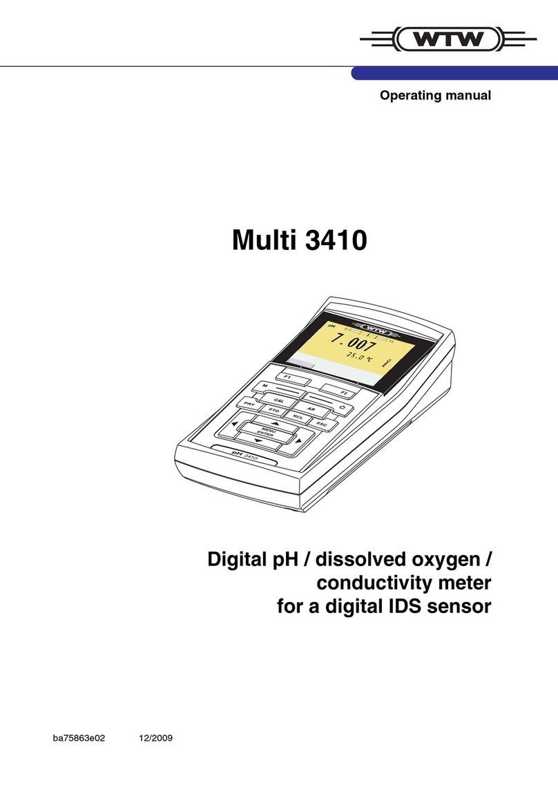
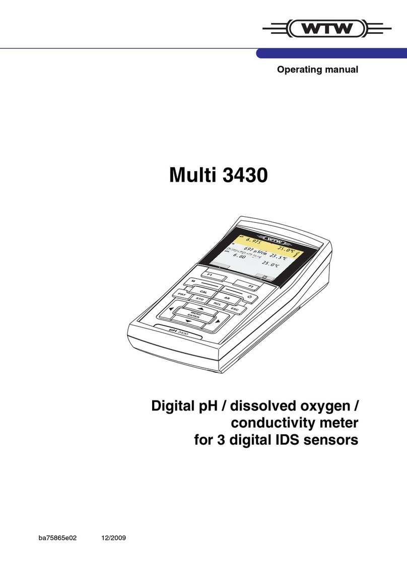
wtw inoLab Multi 720 User manual

inoLab
Multi 720
ba75442e01 03/2004
ba75442e
Operating Manual
Measuring Instrument
for pH, Redox, Dissolved Oxygen
and Conductivity
Multi
720

Accuracy when
going to press The use of advanced technology and the high quality stan-
dard of our instruments are the result of continuous develop-
ment. This may result in differences between this operating
manual and your instrument.
We cannot guarantee that there are absolutely no errors in
this manual. We are sure you willunderstand that we cannot
accept any legal claims resulting from the data, figures or
descriptions.
Warranty declara-
tion The designated instrument is covered by a warranty of three
years from the date of purchase.
The instrument warranty extends to manufacturing faults
that are determined within the period of warranty.
Thewarrantyexcludescomponentsthatarereplacedduring
maintenance such as batteries, etc.
The warranty claim extends to restoring the instrument to
readiness for use but not, however, to any further claim for
damages. Improperhandlingor unauthorized openingof the
instrument invalidates any warranty claim.
To ascertain the warranty liability, return the instrument and
proof of purchase together with the date of purchase freight
paid or prepaid.
Copyright ©Weilheim 2004, WTW GmbH
Reprinting - even as excerpts - is only allowed with the ex-
plicit written authorization of WTW GmbH, Weilheim.
Printed in Germany.

Multi 720 Contents
85
1 Overview . . . . . . . . . . . . . . . . . . . . . . . . . . . . . . 87
1.1 Keypad . . . . . . . . . . . . . . . . . . . . . . . . . . . . . . . 88
1.2 Display . . . . . . . . . . . . . . . . . . . . . . . . . . . . . . . 89
1.3 Sockets. . . . . . . . . . . . . . . . . . . . . . . . . . . . . . . 89
1.4 Operating structure. . . . . . . . . . . . . . . . . . . . . . 90
2 Safety . . . . . . . . . . . . . . . . . . . . . . . . . . . . . . . . . 91
2.1 Authorized use . . . . . . . . . . . . . . . . . . . . . . . . . 92
2.2 General safety instructions. . . . . . . . . . . . . . . . 92
3 Commissioning. . . . . . . . . . . . . . . . . . . . . . . . . 95
4 Operation. . . . . . . . . . . . . . . . . . . . . . . . . . . . . . 97
4.1 Switch on the instrument . . . . . . . . . . . . . . . . . 97
4.2 Measuring the pH value/Redox voltage . . . . . . 98
4.2.1 Measuring the pH value . . . . . . . . . . . 100
4.2.2 Measuring the Redox voltage . . . . . . . 101
4.3 Calibrating for pH measurements. . . . . . . . . . 102
4.3.1 AutoCal TEC . . . . . . . . . . . . . . . . . . . . 104
4.3.2 AutoCal DIN . . . . . . . . . . . . . . . . . . . . 106
4.3.3 ConCal . . . . . . . . . . . . . . . . . . . . . . . . 108
4.4 Measuring the dissolved oxygen . . . . . . . . . . 111
4.4.1 Oxygen concentration . . . . . . . . . . . . . 112
4.4.2 Oxygen saturation . . . . . . . . . . . . . . . . 113
4.4.3 Oxygen partial pressure . . . . . . . . . . . 114
4.4.4 AutoRead AR (drift control) . . . . . . . . . 114
4.5 Calibrating for D. O. measurements. . . . . . . . 116
4.5.1 Starting the calibration. . . . . . . . . . . . . 118
4.5.2 Entering the salt content (salinity) . . . . 120
4.6 Measuring the conductivity. . . . . . . . . . . . . . . 121
4.6.1 Conductivity / Specific resistance . . . . 123
4.6.2 Salinity. . . . . . . . . . . . . . . . . . . . . . . . . 124
4.6.3 TDS (total dissolved solids). . . . . . . . . 125
4.6.4 AutoRead AR (Drift control). . . . . . . . . 126
4.7 Determining/setting up the cell constant [C]. . 127
4.7.1 Determining the cell constant
(calibration in control standard). . . . . . 127

Contents Multi 720
86
4.7.2 Setting up the cell constant . . . . . . . . . 130
4.8 Setting up the temperature compensation TC 133
4.9 Configuration . . . . . . . . . . . . . . . . . . . . . . . . . 137
4.10 Reset . . . . . . . . . . . . . . . . . . . . . . . . . . . . . . . 140
5 Maintenance, cleaning, disposal. . . . . . . . . . 143
5.1 Maintenance. . . . . . . . . . . . . . . . . . . . . . . . . . 143
5.2 Cleaning. . . . . . . . . . . . . . . . . . . . . . . . . . . . . 144
5.3 Disposal . . . . . . . . . . . . . . . . . . . . . . . . . . . . . 144
6 What to do if.... . . . . . . . . . . . . . . . . . . . . . . . . 145
6.1 pH system messages. . . . . . . . . . . . . . . . . . . 145
6.2 Oxygen system messages . . . . . . . . . . . . . . . 147
6.3 Conductivity system messages . . . . . . . . . . . 149
6.4 General errors . . . . . . . . . . . . . . . . . . . . . . . . 149
7 Technical Data . . . . . . . . . . . . . . . . . . . . . . . . 151
7.1 General data. . . . . . . . . . . . . . . . . . . . . . . . . . 151
7.2 pH/Redox measurement . . . . . . . . . . . . . . . . 153
7.3 Oxygen measurement . . . . . . . . . . . . . . . . . . 154
7.4 Conductivity measurement. . . . . . . . . . . . . . . 155
8 Lists. . . . . . . . . . . . . . . . . . . . . . . . . . . . . . . . . 157

Multi 720 Overview
87
1Overview
The compact inoLab Multi 720 precision measuring instru-
ment lets you perform pH, Redox, D. O., and conductivity
measurements rapidly and reliably. The inoLab Multi 720
provides the highest degree of operating comfort, reliability
and measuring safety for all applications.
The proven OxiCal®and MultiCal®calibration procedures
and special AutoRead function support your work with the
instrument.
Note
The measuring instrument can also be delivered as part of
a set.
Information on this and other accessories is available in the
WTW catalog LABORATORY AND FIELD INSTRUMENTATION or
via the Internet.
1Keypad
2Display
3Sockets
Multi
720
3
2
1

Overview Multi 720
88
1.1 Keypad
1Measuring instrument ON/OFF
2Select measuring mode
3Call up calibration procedure
4Activate/deactivate AutoRead
5Confirm inputs, start AutoRead
6Select measuring mode, increase values,
scroll
7Select measuring mode, reduce values,
scroll
4
3
2
1
7
6
5

Multi 720 Overview
89
1.2 Display
1.3 Sockets
Caution
Only connect probes to the instrument that cannot feed ex-
cessive voltages or currents (> SELV and > circuit with cur-
rent limiter). Almost all commercial electrodes - especially
WTW electrodes - meet these requirements.
On socket 4, use the WTW probe StirrOx G only.
Connectors:
1Dissolved oxygen probe or conductivity measuring cell
2pH/Redox electrode
3Temperature probe
4Stirrer (StirrOx G)
5Reference electrode
6Mains power supply (option)
S
tatus
li
ne
Measured value display
Function and
temperature display
1234
5
6

Overview Multi 720
90
1.4 Operating structure
Thefollowingoverviewdiagram shows which keysyouhave
to press to select between the different measuring modes:
Note
When a D. O. probe or a conductivity measuring cell with
temperature probe is connected, the measuring instrument
recognizes the probe or measuring cell and automatically
switches to the oxygen measuring mode or conductivity
measuring mode last selected. As soon as the probe/mea-
suring cell is disconnected, the instrument switches to the
pH or Redox measuring mode.

Multi 720 Safety
91
2 Safety
This operating manual contains basic instructions that you
must follow during the commissioning, operation and main-
tenance of the instrument. Consequently, all responsible
personnel must read this operating manual before working
with the instrument.
The operating manual must always be available within the
vicinity of the instrument.
Target group This measuring instrument was developed for use in the lab-
oratory.
Thus, we assume that, as a result of their professional train-
ing and experience, the operators will know the necessary
safety precautions to take when handling chemicals.
Symbols used
Caution
indicates instructions that have to be followed to prevent
damage to your instrument.
Warning
indicates instructions that have to be followed to protect
yourself and the instrument from dangerous electrical volt-
age.
Note
Indicates notes that draw your attention to special features.
Note
Indicates cross-references to other documents, e.g. appli-
cation reports, operating manuals of combination elec-
trodes, etc.

Safety Multi 720
92
2.1 Authorized use
This instrument is authorized exclusively for measuring the
pH, Redox, dissolved oxygen and conductivity in the labora-
tory.
Thetechnicalspecifications asgiven inchapter7TECHNICAL
DATA, must be observed. Only the operation and running of
themeasuringinstrumentaccordingtotheinstructionsgiven
in this operating manual is authorized.
Any other use is considered unauthorized.
2.2 General safety instructions
Thisinstrumentisconstructedandtestedincompliancewith
the EN 61010-1 safety regulations for electronic measuring
instruments.
It left the factory in a safe and secure technical condition.
Function and opera-
tional safety The smooth functioning and operational safety of the instru-
ment can only be guaranteed if the generally applicable
safety measures and the specific safety instructions in this
operating manual are followed.
The smooth functioning and operational safety of the instru-
ment can only be guaranteed under the climatic conditions
specified in chapter 7 TECHNICAL DATA.
Iftheinstrumentwas transported from acoldenvironmentto
a warm environment, the formation of condensate can lead
to the faulty functioning of the instrument. In this event, wait
until the temperature of the instrument reaches room tem-
perature before putting the instrument back into operation.
Caution
The instrument is only allowed to be opened by personnel
authorized by WTW.

Multi 720 Safety
93
Safe operation If safe operation is no longer possible, the instrument must
be taken out of service and secured against inadvertent op-
eration.
Safe operation is no longer possible if:
lthe instrument has been damaged in transport
lthe instrument has been stored under adverse conditions
for a lengthy period of time
lthe instrument is visibly damaged
lthe instrument no longer operates as described in this
manual
If you are in doubt contact the supplier of the instrument.
Obligations of the
operator The operator of this measuring instrument must ensure that
the following laws and guidelines are observed when using
dangerous substances:
lEEC directives for protective labor legislation
lNational protective labor legislation
lSafety regulations
lSafety datasheets of the chemical manufacturer

Safety Multi 720
94

Multi 720 Commissioning
95
3 Commissioning
Note
You can adapt individual parameters to your requirements.
To do so, change the default settings according to section
4.9 CONFIGURATION.
Connecting the
plug-in power
supply (optional)
The measuring instrument works battery-powered. It can,
however, also be supplied by the plug-in power supply
which is available as an accessory.
Warning
The line voltage on site must lie within the input voltage
range of the original plug-in power supply unit (see chapter
7 TECHNICAL DATA).
Caution
Use original plug-in power supplies only
(see chapter 7 TECHNICAL DATA).
Note
If a stirrer is operated via the measuring instrument, it is
essential to use the plug-in power supply.
1Insert the plug (1) into the socket (2) of the meter.
2 ConnecttheoriginalWTWplug-inpowersupply(3)to
an easily accessible mains socket.
1
2
3

Commissioning Multi 720
96
Scope of delivery lLaboratory measuring instrument, inoLab Multi 720
lOperating manual and short manual
l4 x type AA Mignon 1.5 V batteries

Multi 720 Operation
97
4Operation
4.1 Switch on the instrument
Note
The instrument has an energy saving feature to avoid un-
necessary battery depletion.
The energy saving feature switches the instrument off if no
key has been pressed for an hour.
The energy saving feature is not active if the instrument is
supplied by the plug-in power supply.
1Place the instrument on a flat surface and protect it
against intense light and heat.
2 Press the ekey.
The display test appears briefly on the display.
The instrument then switches automatically to the
measuring mode.
Probe connected Measuring mode
No probe or
pH/Redox electrode pH or Redox measurement
(dependingonthepreviously
selected measuring mode)
D.O.probeorconductivity
measuring cell Previously selected measur-
ing mode
Any 2 probes Previously selected measur-
ing mode
Measuring mode
on switching on

Operation Multi 720
98
4.2 Measuring the pH value/Redox voltage
Preparatory
activities Perform the following preparatory activities when you want
to measure:
Note
Incorrect calibration of the pH electrode will result in incor-
rect measured values. Therefore, regularly perform calibra-
tion before measuring.
Temperature probe Measurements can be performed with and without a temper-
ature probe. A connected temperature probe is indicated by
TP on the display.
Note
If you use a pH electrode without a temperature probe, the
instrument is able to use the temperature probe of a D. O.
probe or conductivity measuring cell that is also connected
to the instrument and is immersed in the test sample. You
have to set up this as described in section 4.9 CONFIGURATI-
ON. The TP display indicator flashes when the temperature
probe of the D. O. probe or conductivity cell is used.
1Press the mkey repeatedly until the pH/Redox
measurement appears on the display.
2 Connect the electrode to the instrument.
3Adjust the temperature of the buffer or test solutions
or measure the current temperature if the measure-
ment is made without a temperature probe.
4 Calibrate or check the instrument with the electrode.
5Select the measuring mode by pressing m.

Multi 720 Operation
99
The temperature measurement is absolutely essential for a
reproducible pH measurement. If the measurement is made
without a temperature probe, proceed as follows:
Note
When calibrating without a temperature probe, set up the
current temperature of the respective buffer solution manu-
ally using the 8or 2keys while pressing and holding
down the gkey.
1Determine the current temperature using a thermo-
meter.
2 Press and hold down the gkey and set up the tem-
perature using 8or 2.

Operation Multi 720
100
4.2.1 Measuring the pH value
AutoRead AR
(Drift control) The AutoRead function (drift control) checks the stability of
the measurement signal. The stability has a considerable ef-
fect on the reproducibility of the measured values.
Foridenticalmeasurementconditions,thefollowingcriterion
applies:
lpH value: better than 0.02 (response time: > 30 s)
1Perform the preparatory activities according to sec-
tion 4.2.
2 Immerse the pH electrode into the test sample.
3Pressthe 8or2keyuntil pHappears inthestatus
display. The pH value appears on the display.
1Call up the pH measuring mode by pressing 82.
2 Immerse the pH electrode into the test sample.
3Activate the AutoRead function by pressing a.
The current measured value is frozen (Hold function).
4 Start the AutoRead function by pressing g.
AR flashes on the display until a stable measured val-
ue is reached.
5If necessary, start the next AutoRead measurement
by pressing g.
6 To terminate the AutoRead function: Press a.

Multi 720 Operation
101
Note
The current AutoRead measurement (with acceptance of
the current value) can be terminated at any time by pressing
g.It isonly possible tochangetoanothermeasuringmode
after AutoRead has been terminated.
4.2.2 Measuring the Redox voltage
The instrument can measure the Redox voltage (mV) of a
solution when connected with a Redox electrode, e.g.
SenTix ORP.
Note
The AutoRange function is always active and automatically
switches to the measuring range with the highest resolution.
Note
Redox electrodes are not calibrated. However, you can
check Redox electrodes using a test solution.
1Perform the preparatory activities according to sec-
tion 4.2.
2 Immerse the Redox electrode into the test sample.
3Press the 82 key repeatedly until U appears in
the status line.
The Redox voltage (mV) of the sample appears on
the display.
4 Wait for a stable measured value.

Operation Multi 720
102
4.3 Calibrating for pH measurements
Why calibrate? pH electrodes age. This changes the asymmetry (zero
point) and slope of the pH electrode. As a result, an inexact
measured value is displayed. Calibration determines the
current values of the asymmetry and slope of the electrode
and they are stored in the instrument.
Thus, you should calibrate at regular intervals.
Note
Always calibrate after connecting another pH electrode.
You can choose between 3 calibration procedures:
AutoCal TEC is specially adapted to the WTW technical buffer solutions
as a fully automatic two-point calibration. The buffer solu-
tions are automatically recognized by the instrument.
AutoCal DIN is specially adapted to permanently programmed buffer so-
lutions according to DIN 19266 as a fully automatic two-
point calibration. The buffer solutions are automatically rec-
ognized by the instrument.
ConCal is the conventional two-point calibration with 2 freely
selectable buffer solutions or single-point calibration as the
rapid method.
AutoRead In calibration using AutoCal TEC and AutoCal DIN, the Au-
toRead function is automatically activated.
The current AutoRead measurement (with acceptance of
the current value) can be terminated at any time by pressing
g.
Calibration
evaluation After the calibration, the instrument automatically evaluates
the current status. The asymmetry and slope are separately
evaluated. The worst evaluation appears on the display.
Table of contents
Other wtw Measuring Instrument manuals

wtw
wtw Oxi 197i User manual

wtw
wtw Oxi 7310 User manual

wtw
wtw MultiLine SensoLyt 900-P User manual

wtw
wtw OxiTop IS 6 User manual

wtw
wtw Cond 315i User manual

wtw
wtw Cond 3110 User manual

wtw
wtw EcoLine pH 170 User manual

wtw
wtw PurCon User manual

wtw
wtw inoLab Oxi Level 2 User manual

wtw
wtw Multi 350i User manual