wtw Multi 197i User manual

Multi 197i
ba75339e04 07/2009
Operating manual
RUN / ENTER
AUTO READ
CAL
STO
M
RCL
ON / OFF
Multi 197i
mg/l
O
7
176
92
°
C
ARng
TP
REL1
Portable pH / oxygen / conductivity measuring instrument

ba75339e04 07/2009
Accuracy when
going to press
The use of advanced technology and the high quality standard of our
instruments are the result of a continuous development. This may re-
sult in differences between this operating manual and your instrument.
Also, we cannot guarantee that there are absolutely no errors in this
manual. Therefore, we are sure you will understand that we cannot ac-
cept any legal claims resulting from the data, figures or descriptions.
Copyright ©Weilheim 2005, WTW GmbH
Reproduction in whole - or even in part - is prohibited without the ex-
press written permission of WTW GmbH, Weilheim.
Printed in Germany.

Multi 197i List of contents
3
ba75339e04 07/2009
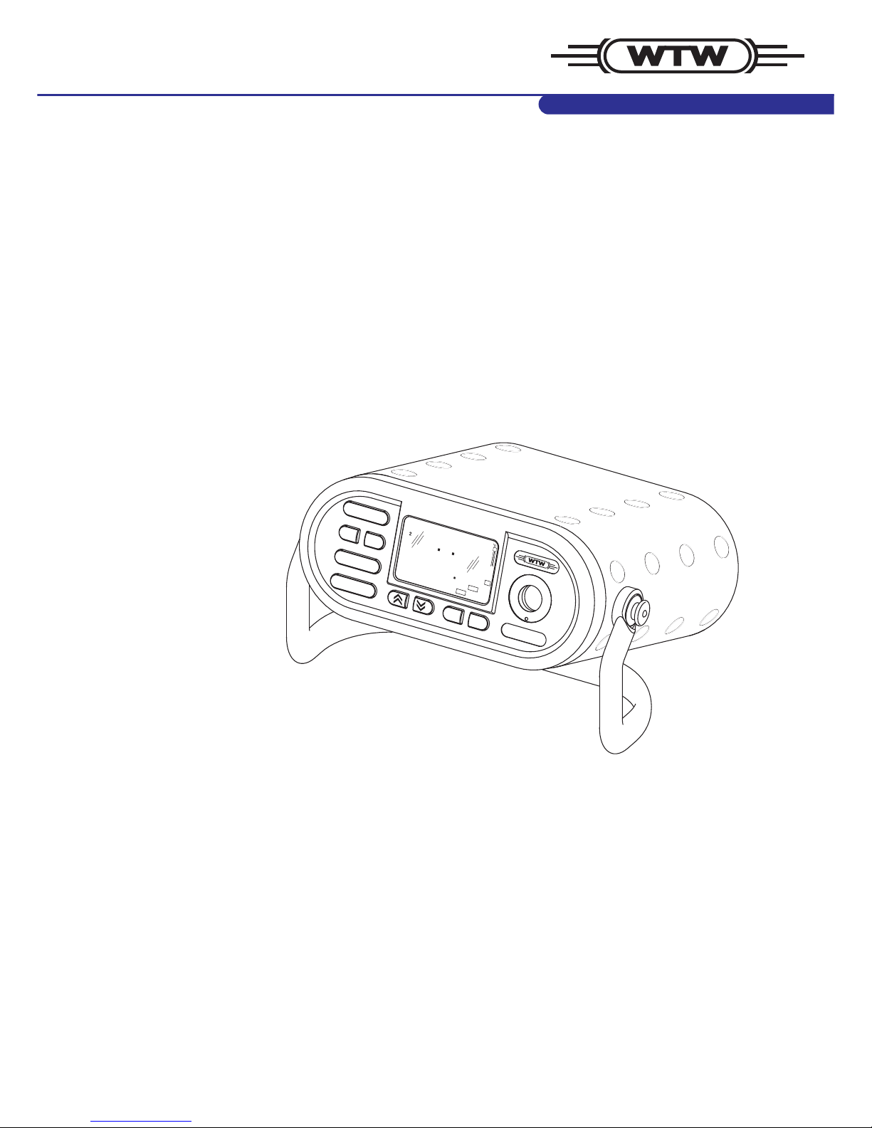
1 Overview . . . . . . . . . . . . . . . . . . . . . . . . . . . . . . . . . . . . . 5
1.1 General features . . . . . . . . . . . . . . . . . . . . . . . . . . . . . . . 5
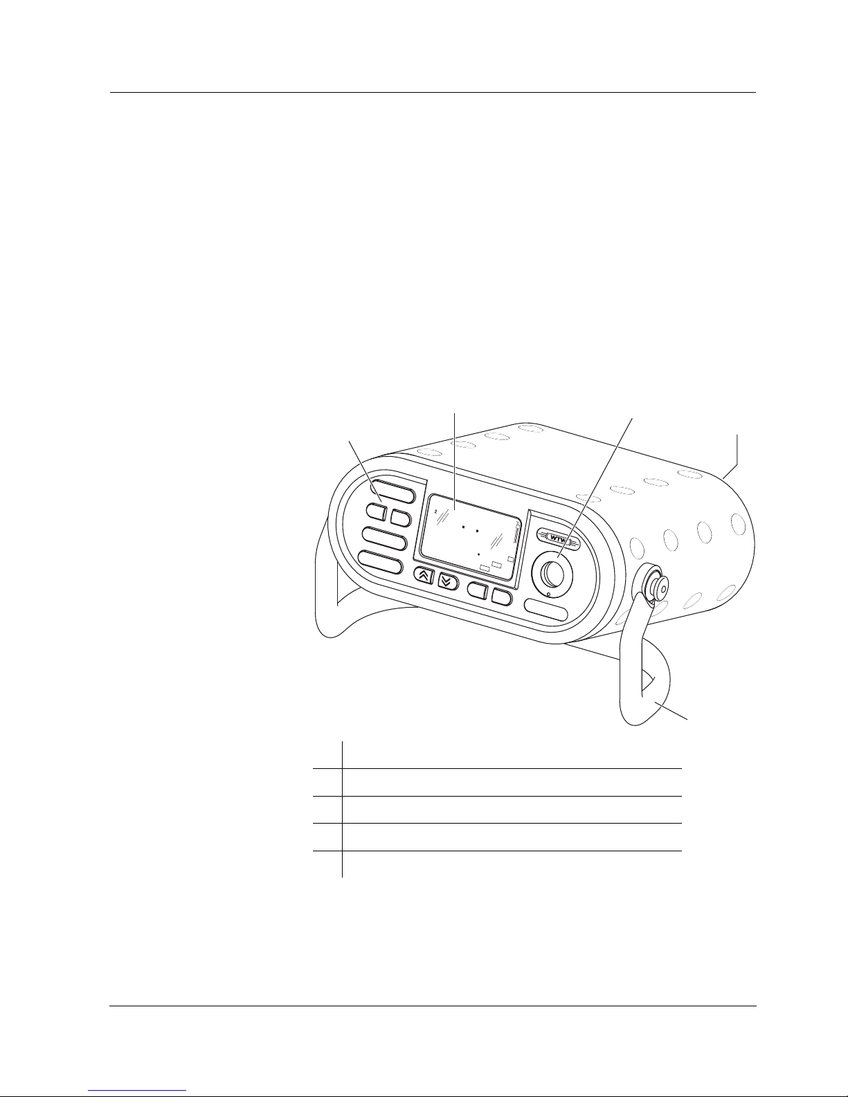
1.2 Display . . . . . . . . . . . . . . . . . . . . . . . . . . . . . . . . . . . . . . . 6
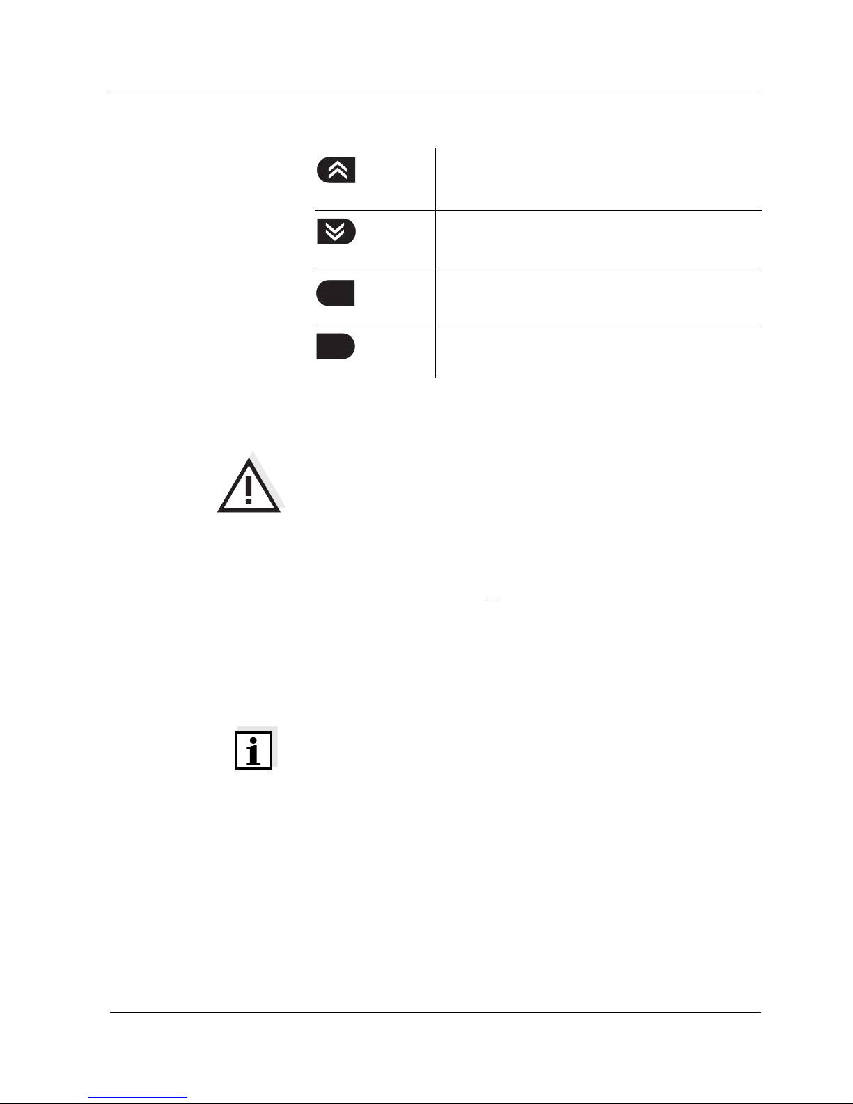
1.3 Keypad . . . . . . . . . . . . . . . . . . . . . . . . . . . . . . . . . . . . . . . 6
1.4 Jack field . . . . . . . . . . . . . . . . . . . . . . . . . . . . . . . . . . . . . 7
2 Safety . . . . . . . . . . . . . . . . . . . . . . . . . . . . . . . . . . . . . . . . 9
2.1 Authorized use . . . . . . . . . . . . . . . . . . . . . . . . . . . . . . . . . 9
2.2 General safety instructions . . . . . . . . . . . . . . . . . . . . . . . 10
3 Commissioning. . . . . . . . . . . . . . . . . . . . . . . . . . . . . . . 11
3.1 Scope of delivery . . . . . . . . . . . . . . . . . . . . . . . . . . . . . . 11
3.2 Power supply . . . . . . . . . . . . . . . . . . . . . . . . . . . . . . . . . 11
3.3 Initial commissioning . . . . . . . . . . . . . . . . . . . . . . . . . . . 12
3.4 Sensor quiver . . . . . . . . . . . . . . . . . . . . . . . . . . . . . . . . . 14
4 Operation. . . . . . . . . . . . . . . . . . . . . . . . . . . . . . . . . . . . 15
4.1 Operating structure . . . . . . . . . . . . . . . . . . . . . . . . . . . . 15
4.2 Switching on the measuring instrument . . . . . . . . . . . . . 16
4.3 pH value / ORP voltage . . . . . . . . . . . . . . . . . . . . . . . . . 17
4.3.1 General information . . . . . . . . . . . . . . . . . . . . . . 17
4.3.2 Measuring the pH value . . . . . . . . . . . . . . . . . . 19
4.3.3 Measuring the ORP voltage . . . . . . . . . . . . . . . 20
4.3.4 pH calibration . . . . . . . . . . . . . . . . . . . . . . . . . . 21
4.4 Dissolved oxygen . . . . . . . . . . . . . . . . . . . . . . . . . . . . . . 27
4.4.1 General information . . . . . . . . . . . . . . . . . . . . . . 27
4.4.2 Measuring the D. O. concentration . . . . . . . . . . 29
4.4.3 Measuring the D. O. saturation . . . . . . . . . . . . . 30
4.4.4 AutoRead AR (Drift control) and hold function . 31
4.4.5 D. O. calibration . . . . . . . . . . . . . . . . . . . . . . . . 32
4.4.6 Entering the salt content (salinity) . . . . . . . . . . . 35
4.5 Conductivity . . . . . . . . . . . . . . . . . . . . . . . . . . . . . . . . . . 36
4.5.1 General information . . . . . . . . . . . . . . . . . . . . . . 36
4.5.2 Measuring the conductivity . . . . . . . . . . . . . . . . 38
4.5.3 Measuring the salinity . . . . . . . . . . . . . . . . . . . . 38
4.5.4 AutoRead AR (Drift control) and hold function . 39
4.5.5 Determining the cell constant (Calibration in the
control standard) . . . . . . . . . . . . . . . . . . . . . . . . 40
4.6 Calibration intervals (Int 3, Int 4, Int 5) . . . . . . . . . . . . . . 43
4.7 Saving data . . . . . . . . . . . . . . . . . . . . . . . . . . . . . . . . . . 44
4.7.1 Saving manually . . . . . . . . . . . . . . . . . . . . . . . . 44
4.7.2 Switching on AutoStore (Int 1) . . . . . . . . . . . . . 46
4.7.3 Outputting the data storage . . . . . . . . . . . . . . . . 48
4.7.4 Clearing the memory . . . . . . . . . . . . . . . . . . . . . 54

List of contents Multi 197i
4ba75339e04 07/2009
4.8 Transmitting data . . . . . . . . . . . . . . . . . . . . . . . . . . . . . . 55
4.8.1 Data transmission interval (Int 2) . . . . . . . . . . . . 55
4.8.2 PC/external printer (RS232 interface) . . . . . . . . 57
4.8.3 Remote control . . . . . . . . . . . . . . . . . . . . . . . . . 57
4.9 Configuration . . . . . . . . . . . . . . . . . . . . . . . . . . . . . . . . . 58
4.10 Reset . . . . . . . . . . . . . . . . . . . . . . . . . . . . . . . . . . . . . . . 62
5 Maintenance, cleaning, disposal . . . . . . . . . . . . . . . . . 65
5.1 Maintenance . . . . . . . . . . . . . . . . . . . . . . . . . . . . . . . . . . 65
5.2 Cleaning . . . . . . . . . . . . . . . . . . . . . . . . . . . . . . . . . . . . . 65
5.3 Disposal . . . . . . . . . . . . . . . . . . . . . . . . . . . . . . . . . . . . . 65
6 What to do if... . . . . . . . . . . . . . . . . . . . . . . . . . . . . . . . . 67
6.1 pH system messages . . . . . . . . . . . . . . . . . . . . . . . . . . . 67
6.2 Oxi system messages . . . . . . . . . . . . . . . . . . . . . . . . . . . 69
6.3 Conductivity system messages . . . . . . . . . . . . . . . . . . . 70
6.4 General errors . . . . . . . . . . . . . . . . . . . . . . . . . . . . . . . . . 71
7 Technical data . . . . . . . . . . . . . . . . . . . . . . . . . . . . . . . . 73
7.1 General data . . . . . . . . . . . . . . . . . . . . . . . . . . . . . . . . . . 73
7.2 Measuring ranges, resolutions, accuracies . . . . . . . . . . 74
7.2.1 pH/ORP . . . . . . . . . . . . . . . . . . . . . . . . . . . . . . . 74
7.2.2 Dissolved oxygen . . . . . . . . . . . . . . . . . . . . . . . . 75
7.2.3 Conductivity . . . . . . . . . . . . . . . . . . . . . . . . . . . . 76
8 Lists . . . . . . . . . . . . . . . . . . . . . . . . . . . . . . . . . . . . . . . . 77

Multi 197i Overview
5
ba75339e04 07/2009
1Overview
1.1 General features
The Multi 197i portable multiparameter measuring instrument enables
you to carry out pH measurements, dissolved oxygen (D. O.) measure-
ments and conductivity measurements quickly and reliably.
The Multi 197i provides the maximum degree of operating comfort, re-
liability and measuring certainty for all applications.
The proven MultiCal® and OxiCal®calibration procedures and the pro-
cedures to determine/set up the cell constant support you in your work
with the meter. The special AutoRead function enables precise mea-
surements.
1Keypad
2Display
3Integrated, exchangeable sensor quiver
4Jack field
5Carrying and positioning handle
RUN / ENTER
AUTO READ
CAL
STO
M
RCL
ON / OFF
Multi 197i
mg/l
O
7
176
92
°
C
ARng
TP
REL1
1
23
4
5

Overview Multi 197i
6ba75339e04 07/2009
Note
If you need further information or application notes, you can obtain the
following material from WTW:
zApplication reports
zPrimers
zSafety datasheets.
You will find information on available literature in the WTW catalog or
via the Internet.
1.2 Display
1.3 Keypad
Key functions
Lin
K
/
%
pHmV/
Sal
mcm
S/
cm
1/
%
mg/l
pH
S
Sal
O
8
8888
88
1
°
C
Time
Year
LoBat nLF
Oxi
Cal
TEC
ARng
AR
RCL
Ident
Tref25 Tref20
Auto
Store
REL2
TP
No.
Day.Month
Baud
REL1
Status display indicator
Measured value
Function and
temperature display
Sensor symbol
display
Switch measuring instrument on/off
<ON/OFF>
Select the measured variable <M>:
– pH value / ORP voltage
– D. O. concentration / D. O. saturation
– Conductivity / salinity
Calibrate the currently set measured variable
<CAL>
Activate/deactivate the AutoRead function
<AUTO READ>
Confirm entries, start AutoRead,
output measured values
<RUN/ENTER>
ON / OFF
M
CAL
AUTO READ
RUN / ENTER

Multi 197i Overview
7
ba75339e04 07/2009
1.4 Jack field
Warning
Only connect sensors to the measuring instrument that cannot return
any voltages or currents that are not allowed (> SELV and > current cir-
cuit with current limiting).
Almost all sensors - in particular WTW sensors - fulfill these conditions.
Maximum number
of sensors to be con-
nected
The following sensors can be connected to the Multi 197i (maximum
configuration):
zOne pH depth armature or one pH electrode (combination electrode
or pH electrode + reference electrode). Please make sure that only
one pH sensor is connected at the same time.
zOne D. O. sensor
zOne conductivity measuring cell
zOption: One external temperature sensor
Note
The pH depth armature is affected by other sensors if it is connected to
them galvanically. For this reason, the pH depth armature cannot be
operated in the same test sample together with another sensor on the
instrument.
Select the measuring mode, increase values,
scroll
<▲>
Select the measuring mode, decrease values,
scroll
<▼>
Display/transmit measured values
<RCL>
Save a measured value
<STO>
RCL
STO

Overview Multi 197i
8ba75339e04 07/2009
Connectors:
Note
The sensor sockets, 1and 2must not be assigned at the same time.
On the two sockets, 5and 6, only different sensor types (Oxi and Cond)
may be connected at the same time.
Sensor / Instrument Socket / Posi-
tion
pH depth armature 1
pH electrode or pH combination electrode 2
pH combination electrode with temperature sensor 2and 4
Reference electrode 3
Temperature sensor, external 3and 4
Oxygen sensor 5or 6
Conductivity measuring cell 5or 6
Printer or PC (serial interface, RS232) 7
Plug-in power supply unit 8
Watertight valve for internal pressure equalization 9
1
5
34
6
2
9
7
8

Multi 197i Safety
9
ba75339e04 07/2009
2 Safety
This operating manual contains basic instructions that you must follow
during the commissioning, operation and maintenance of the measur-
ing instrument. Consequently, all responsible personnel must read this
operating manual before working with the measuring system. The op-
erating manual must always be available within the vicinity of the mea-
suring system.
Target group The measuring instrument was developed for work in the field and in
the laboratory.
Thus, we assume that, as a result of their professional training and ex-
perience, the operators will know the necessary safety precautions to
take when handling chemicals.
Safety instructions The individual chapters of this operating manual use the following safe-
ty instruction to indicate various types of danger:
Warning
indicates instructions that must be followed precisely in order to avoid
the possibility of slight injuries or damage to the instrument or the envi-
ronment.
Further notes
Note
indicates notes that draw your attention to special features.
Note
indicates cross-references to other documents, e.g. operating manu-
als.
2.1 Authorized use
The authorized use of the measuring instrument consists exclusively of
the:
zpH and ORP measurement
zmeasurement of the oxygen content and
zmeasurement of the conductivity, salinity and temperature
in the field and laboratory.
The technical specifications as given in chapter 7 TECHNICAL DATA
must be observed. Only the operation and running of the measuring in-
strument according to the instructions given in this operating manual is
authorized. Any other use is considered to be unauthorized.

Safety Multi 197i
10 ba75339e04 07/2009
2.2 General safety instructions
This instrument is built and inspected according to the relevant guide-
lines and norms for electronic measuring instruments (see chapter
7T
ECHNICAL DATA).
It left the factory in a safe and secure technical condition.
Function and operating
safety
The smooth functioning and operational safety of the measuring instru-
ment can only be guaranteed if the generally applicable safety mea-
sures and the specific safety instructions in this operating manual are
followed during operation.
The smooth functioning and operational safety of the measuring instru-
ment can only be guaranteed under the environmental conditions that
are specified in chapter 7 TECHNICAL DATA.
If the instrument was transported from a cold environment to a warm
environment, the formation of condensate can lead to the faulty func-
tioning of the instrument. In this event, wait until the temperature of the
instrument reaches room temperature before putting the instrument
back into operation.
Safe operation If safe operation is no longer possible, the instrument must be taken out
of service and secured against inadvertent operation!
Safe operation is no longer possible if the measuring instrument:
zhas been damaged in transport
zhas been stored under adverse conditions for a lengthy period of
time
zis visibly damaged
zno longer operates as described in this manual.
If you are in any doubt, please contact the supplier of the instrument.
Obligations of the pur-
chaser
The purchaser of the measuring instrument must ensure that the fol-
lowing laws and guidelines are observed when using dangerous sub-
stances:
zEEC directives for protective labor legislation
zNational protective labor legislation
zSafety regulations
zSafety datasheets of the chemical manufacturers.

Multi 197i Commissioning
11
ba75339e04 07/2009
3 Commissioning
3.1 Scope of delivery
zMulti 197i portable multiparameter measuring instrument with inte-
grated rechargeable battery
zCarrying and positioning handle
zCarrying strap
z2 sensor quivers (pH and Oxi-LF type)
zPlug-in power supply unit
zOperating manual
3.2 Power supply
Mains operation and
charging the battery
You can either operate the measuring instrument with the integrated re-
chargeable battery or with the plug-in power supply. The plug-in power
supply supplies the measuring instrument with low voltage (12 V DC).
At the same time, the rechargeable battery is charged.
Charging time of the
battery
approx. 5 hours. The battery is charged even when the instrument is
switched off. The LoBat display indicator appears when the battery is
nearly empty and has to be charged as soon as possible.
Warning
The line voltage at the operating site must lie within the input voltage
range of the original plug-in power supply (see chapter 7 TECHNICAL DA-
TA).
Warning
Use original plug-in power supplies only (see
chapter 7 TECHNICAL DATA).

Commissioning Multi 197i
12 ba75339e04 07/2009
Connecting the plug-in
power supply unit
3.3 Initial commissioning
Perform the following activities:
zFor mains operation and charging the battery: Connect the plug-in
power supply (see section 3.2 POWER SUPPLY).
zSet the date and time.
Setting the date and
time
1Connect the plug (1) to the socket (2) of the measuring instru-
ment.
2 Connect the original WTW plug-in power supply (3) to an easily
accessible mains socket.
2
1
3
1Press the <M> key and hold it down.
2 Press the <ON/OFF> key.
The display test appears briefly on the display.
3Press the <RUN/ENTER> key repeatedly until the date flashes
on the display (Day.Month display indicator).

Multi 197i Commissioning
13
ba75339e04 07/2009
4Set the date of the current day with <▲> <▼>.
5 Confirm with <RUN/ENTER>.
The date (month) flashes in the display.
6Set the current month with <▲> <▼>.
7 Confirm with <RUN/ENTER>.
The year appears on the display.
8Set the current year with <▲> <▼>.
9 Confirm with <RUN/ENTER>.
The hours flash on the display.
10 Set the current time with <▲> <▼>.
11 Confirm with <RUN/ENTER>.
The minutes flash on the display.
12 Set the current time with <▲> <▼>.
13 Confirm with <RUN/ENTER>.
The instrument switches to the measuring mode.
REL1
Tref25
5t2
Time
Cal
I
O
AR
cm
1/
TP
ARng
nLF
°
C
cm
S/
Sal
RCL
%
S
%
m
mg/l
Oxi
Year
Ident
No.
Tref20
LoBat
Lin
Sal
pH
TEC
Auto
Store
Baud
K
/
REL2
pH/mV
Day.Month
0 9 0 4

Commissioning Multi 197i
14 ba75339e04 07/2009
3.4 Sensor quiver
To store the sensors during field operation and to keep the sensor ele-
ment moist, the quiver tip contains a sponge rubber insert that can be
moistened with deionized water.
Note
For further details on proper storage, refer to the operating manual of
the sensor.
Moistening the
quiver insert
Warning
Do not store pH electrodes in the quiver for more than 10 hours. To
store them for a longer period of time, use the watering cap filled with
potassium chloride (3 mol/l) of the electrode.
1Press the quiver out of the holder from the back side of the in-
strument and pull it out completely.
2 Pull off the quiver tip and moisten the sponge rubber with
deionized water.

Multi 197i Operation
15
ba75339e04 07/2009
4 Operation
4.1 Operating structure
Active and inactive REL
socket
In addition to the pH/ORP sensor, the sensor on the REL1 or REL2
socket can be actuated (switched "active"). The other socket is not ac-
tuated ("inactive"). This switching over inside the instrument is made
with the aid of a relay. The active REL socket is shown on the display.
The measured variable on the display can be selected as follows using
the <M> key:
Several measuring modes are available within a measured variable.
Switch over between the measured variables with the <▲>or <▼>key.
The options are summarized in the following diagram:
zPress <M> shortly: Switch between the pH/ORP sensor and
the sensor at the active REL socket
zPress <M> for a longer
period of time:
Change the active Rel socket

Operation Multi 197i
16 ba75339e04 07/2009
Note
When a sensor is connected to the active REL socket, the measuring
instrument recognizes the sensor or the measuring cell and automati-
cally switches to the measuring mode that was last active. As soon as
the sensor is disconnected from the active REL socket, the instrument
switches to the pH (mV) measuring mode again.
4.2 Switching on the measuring instrument
Measuring mode when
switching on
Note
The measuring instrument has an energy saving feature to avoid un-
necessary battery depletion. The energy saving feature switches the
measuring instrument off if no key has been pressed for an hour.
The energy saving feature is not active
zif the power is supplied by the plug-in power supply,
zif the AutoStore function is active,
zif the communication cable and a PC with a running communication
program are connected,
zif the printer cable is connected (for external printers).
1Press the <ON/OFF> key.
The display test appears briefly on the display.
After this, the measuring instrument automatically switches to
the measuring mode.
Sensors on the socket Measuring mode
pH REL
(active)
REL
(inactive)
pH or ORP mea-
surement - depend-
ing on the last
selected setting
:
:
::
:Last selected mea-
suring mode.
Only the last active
REL socket is tak-
en into account
::
:::

Multi 197i Operation
17
ba75339e04 07/2009
4.3 pH value / ORP voltage
4.3.1 General information
Preparatory activities Perform the following preparatory activities when you want to measure:
Note
Incorrect calibration of pH electrodes leads to incorrect measured val-
ues. Calibrate regularly before measuring. You can only connect elec-
trodes of the NTC30 type or without temperature sensor.
Warning
When connecting an earthed PC/printer, measurements cannot be per-
formed in earthed media as incorrect values would result. The RS232
interface is not galvanically isolated.
1Connect the pH depth armature or the pH electrode to the mea-
suring instrument.
If necessary, press the <M> key repeatedly until the pH (pH
measurement) or U(measurement of the ORP voltage) display
appears.
2 Adjust the temperature of the buffer solutions or test solutions,
or measure the current temperature, if you measure without a
temperature sensor.
3Calibrate or check the measuring instrument with the elec-
trode.
4 Using <▲> <▼>, toggle between the pH or mV measuring
modes.

Operation Multi 197i
18 ba75339e04 07/2009
Temperature measure-
ment in pH measure-
ments
You can perform pH measurements with or without a temperature sen-
sor as well as with the temperature sensor of an oxygen sensor or a
conductivity measuring cell. The measuring instrument recognizes
which sensors are connected and switches automatically to the correct
mode for the temperature measurement.
The following cases are distinguishable.
* If you do not wish that, you can:
– either disconnect the 2nd sensor and use the manual temperature
input or
– use an electrode with a temperature sensor.
If a temperature sensor is connected, it is indicated on the display by
TP.
Note
When calibrating without a temperature sensor (no TP display indicator
displayed), enter the current temperature of the respective buffer solu-
tion manually using the <▲> <▼>keys while keeping the <RUN/EN-
TER> key depressed.
Temperature sensor Display Mode
pH Cond or
Oxi
yes - TP Automatic with
pH temperature sensor
yes yes TP
- - Manual
-yesTP
flashes
The temperature value of the
second sensor (Cond or Oxi)
in the same sample is taken
over for the pH measurement*

Multi 197i Operation
19
ba75339e04 07/2009
4.3.2 Measuring the pH value
AutoRead AR
(Drift control) and hold
function
The AutoRead function (drift control) checks the stability of the mea-
surement signal. The stability has a considerable impact on the repro-
ducibility of the measured values. With the aid of the hold function the
measured value display is frozen.
With identical measurement conditions, the following criterion is valid
for the AutoRead function:
For D. O. measurements, use the AutoRead function and hold function
like this:
1Perform the preparatory activities according to section 4.3.1.
2 Immerse the pH electrode in the test sample.
3Press the <▲> <▼>keys repeatedly until pH appears on the
status display. The pH value appears on the display.
4When measuring without a connected temperature sensor:
Options:
zDetermine the current temperature using a thermometer
and, while keeping the <RUN/ENTER> key depressed, en-
ter this temperature value with <▲> <▼>.
zTP display indicator not displayed, socket for the second
sensor is free:
Connect the second sensor (Oxi or Cond) and immerse it in
the same sample. TP flashes, the temperature is automati-
cally measured using the second sensor.
AR
1
LoBat nLF
Lin
Oxi
Tref25 Tref20
Cal
TEC
ARng
Auto
Store
8
Time
Year
Ident
No.
Day.Month
Baud
Sal
cm
1/
K
/
%
RCL
REL2
pH/mV
m
cm
S/
%
mg/l
Sal
O
S
pH
6
248
99
°
C
TP
REL1
Reproducibility Response time
Better than 0.02 > 30 seconds
1Call up the pH measuring mode with <▲> <▼>.

Operation Multi 197i
20 ba75339e04 07/2009
Note
The current AutoRead measurement can be terminated at any time
(accepting the current value) by pressing <RUN/ENTER>.
4.3.3 Measuring the ORP voltage
In conjunction with an ORP electrode, e.g. SenTix ORP, the measuring
instrument can measure the ORP voltage (U) of a solution.
Note
ORP electrodes are not calibrated. However, you can check ORP elec-
trodes using a test solution.
2 Activate the AutoRead function with <AUTO READ>.
The current measured value is frozen (hold function).
3Start AutoRead with <RUN/ENTER>.
AR flashes until a stable measured value is reached.
This measured value is transmitted to the interface.
4 If necessary, start the next AutoRead measurement with
<RUN/ENTER>.
5To terminate the AutoRead function: Press the
<AUTO READ> key.
1Perform the preparatory activities according to section 4.3.1.
2 Submerse the ORP electrode in the sample.
3Press the <▲> <▼>key until the Ustatus display appears. The
ORP voltage (mV) of the test sample appears on the display.
4 Wait for a stable measured value.
%
TEC
Store
Oxi
Cal
Auto
No.
Lin
Tref20
8
pH
AR
6
1
LoBat nLF
Tref25
Time
Year
Ident
Day.Month
Baud
Sal
cm
1/
K
/
RCL
REL2
pH/
m
cm
S/
%
mg/l
Sal
O
S
23
mV
REL1
TP
248
°
C
ARng
Table of contents
Other wtw Measuring Instrument manuals

wtw
wtw Turb 430 IR/T User manual

wtw
wtw pHotoFlex pH User manual

wtw
wtw LR 925/01 User manual

wtw
wtw Oxi 3310 IDS User manual

wtw
wtw Multi 350i User manual

wtw
wtw PhotoLab S6 User manual

wtw
wtw inoLab Multi 9310 IDS User manual

wtw
wtw pH 3310 User manual

wtw
wtw pH 197i User manual

wtw
wtw IQ SENSOR NET System 2020 XT User manual