wtw Turb 350 IR User manual

Turb 350 IR
ba41114e02 04/2003 43
Operating manual
Portable Turbidimeter

44
Status at time of
going to press The use of advanced technology and the high quality stan-
dard of our instruments are the result of a continuous devel-
opment. This may result in differences between this
operating manual and your instrument. Also, we cannot
guarantee that there are absolutely no errors in this manual.
Therefore, we are sure you will understand that we cannot
accept any legal claims resulting from the data, figures or
descriptions.
Copyright ©Weilheim 2000, WTW GmbH & Co. KG
Reproduction inwhole-or evenin part-isprohibitedwithout
the express written permission of WTW GmbH & Co. KG,
Weilheim.
Printed in Germany.

List of contents
45
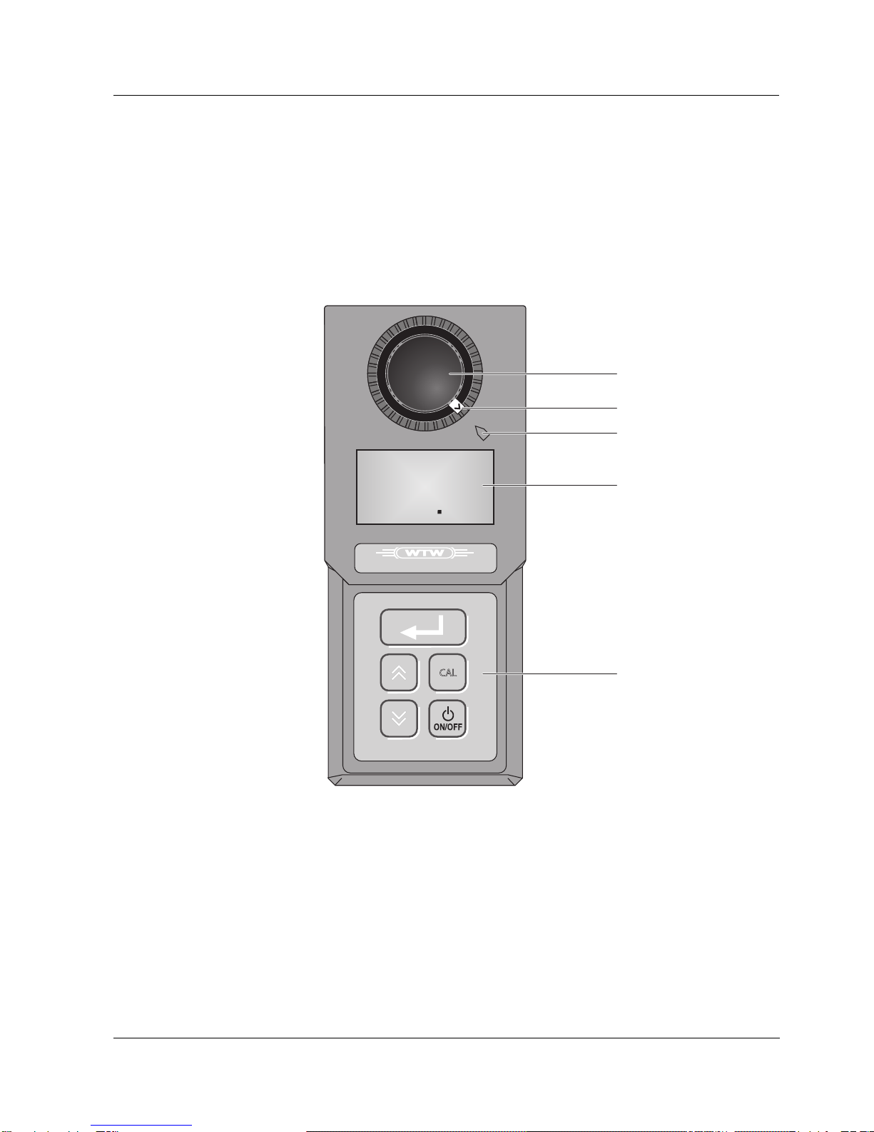
1 Overview . . . . . . . . . . . . . . . . . . . . . . . . . . . . . . 47
1.1 Display . . . . . . . . . . . . . . . . . . . . . . . . . . . . . . . .48
1.2 Keypad . . . . . . . . . . . . . . . . . . . . . . . . . . . . . . .49
2 Safety . . . . . . . . . . . . . . . . . . . . . . . . . . . . . . . . 51
2.1 Authorized use . . . . . . . . . . . . . . . . . . . . . . . . .52
2.2 General safety instructions . . . . . . . . . . . . . . . .52
3 Commissioning . . . . . . . . . . . . . . . . . . . . . . . . 55
3.1 Scope of delivery . . . . . . . . . . . . . . . . . . . . . . . .55
3.2 Initial commissioning . . . . . . . . . . . . . . . . . . . . .55
4 Operation . . . . . . . . . . . . . . . . . . . . . . . . . . . . . 57
4.1 Instructions for operating . . . . . . . . . . . . . . . . . .57
4.1.1 Marking and aligning cuvettes . . . . . . . .57
4.1.2 Venting the sample . . . . . . . . . . . . . . . . .59
4.2 Measuring turbidity . . . . . . . . . . . . . . . . . . . . . .60
4.3 Calibration . . . . . . . . . . . . . . . . . . . . . . . . . . . . .63
4.3.1 Basic information on calibration . . . . . . .63
4.3.2 Calibration procedures . . . . . . . . . . . . . .63
4.3.3 Preparing the calibration . . . . . . . . . . . .65
4.3.4 Four-point calibration . . . . . . . . . . . . . . .65
4.3.5 Partial calibration . . . . . . . . . . . . . . . . . .67
5 Maintenance, cleaning, disposal . . . . . . . . . . 71
5.1 Changing the batteries . . . . . . . . . . . . . . . . . . .71
5.2 Cleaning . . . . . . . . . . . . . . . . . . . . . . . . . . . . . .73
5.2.1 Cleaning the measuring instrument . . . .73
5.2.2 Cleaning the cuvettes . . . . . . . . . . . . . . .73
5.3 Disposal . . . . . . . . . . . . . . . . . . . . . . . . . . . . . . .74
6 What to do if... . . . . . . . . . . . . . . . . . . . . . . . . . 75
7 Technical data . . . . . . . . . . . . . . . . . . . . . . . . . 77
8 Accessories, Options . . . . . . . . . . . . . . . . . . . 79
9 Lists . . . . . . . . . . . . . . . . . . . . . . . . . . . . . . . . . . 81

List of contents
46

Overview
47
1Overview
The Turb 350 IR enables rapid and reliable turbidity mea-
surements to be carried out on individual samples. This
complies with the measuring method used by ISO 7027 /
DIN EN 27027.
1
2
3
Cuvette
Alignment ring
Mark
4
5Display
Keypad
TURB 350 IR
CAL
4283
NTU
1
2
3
4
5

Overview
48
1.1 Display
The LCD display has the following display elements:
1Calibration symbol - instrument in the Calibration
mode
2- Numberof theselected calibrationstandard(when
the CAL display appears), or:
- Error number (flashes when the error symbol
appears)
3Error symbol - flashes when an error occurs
4Battery symbol - flashes if the battery needs to be
changed
5Measuring unit NTU
6Main line
...8
NTU
CAL ERR
13
2
4
123 4
5
6

Overview
49
1.2 Keypad
The Turb 350 IR has a keypad with the following 5 keys:
Key Function
Switch measuring instrument on/off
Increase a value;
Select settings
Start measurement
Reduce value;
Select settings
Call up Calibration mode
CAL

Overview
50

Safety
51
2 Safety
This operating manual contains basic instructions that you
must follow during the commissioning, operation and main-
tenance of the measuring instrument. Consequently, all re-
sponsible personnelmustreadthisoperatingmanualbefore
working with the measuring instrument.
The operating manual must always be available within the
vicinity of the measuring instrument.
Target group The measuring instrument was developed for measure-
ments on site and in the laboratory. We assume that, due to
their professional training and experience, operators are fa-
miliar with the safety measures that are necessary when
handling chemicals.
Symbols
used
Warning
indicates instructions that have to be followed to prevent
damage to your instrument.
Note
indicates notes that draw your attention to special features.
Note
indicates cross-references to other documents, e.g. Appli-
cation reports.

Safety
52
2.1 Authorized use
Authorized use consists exclusively of the turbidity mea-
surement of individual samples on site or in a laboratory en-
vironment.
The technical specifications given in the TECHNICAL DATA
chapter must be observed. Only the operation and running
of the measuring instrument according to the instructions
given in this operating manual is authorized. Any other use
is considered unauthorized.
2.2 General safety instructions
This instrument left the factory in a technically safe and se-
cure condition.
Function and
operating safety The smooth functioning and operational safety of the mea-
suring instrument can only be guaranteed if the generally
applicable safety measures and the specific safety instruc-
tions that appear in this operating manual are followed dur-
ing operation.
The smooth functioning and operational safety of the mea-
suring instrument can only be guaranteed under the climatic
conditions specified in the chapter, TECHNICAL DATA.
Iftheinstrumentwas transported from acoldenvironmentto
a warm environment, the formation of condensate can im-
pair the functioning of the instrument. In this event, wait until
the temperature of the instrument reaches room tempera-
ture before putting the instrument back into operation.

Safety
53
Safe operation If safe operation is no longer possible, the instrument must
be taken out of service and secured against inadvertent op-
eration!
Safe operation is no longer possible if the measuring instru-
ment
lhas been damaged in transport
lhas been stored under adverse conditions for a lengthy
period of time
lis visibly damaged
lno longer operates as described in this manual.
If you are in any doubt, please contact the supplier of the in-
strument.
Obligations of the
operator The purchaser of this measuring instrument must ensure
that the following laws and guidelines are observed when
using dangerous substances:
lEEC directives for protective labor legislation
lNational protective labor legislation
lSafety regulations
lSafety datasheets of the chemical manufacturers.

Safety
54

Commissioning
55
3 Commissioning
3.1 Scope of delivery
lTurb 350 IR portable turbidity measuring instrument
lOperating manual
l4 calibration standards (0.02 / 10.0 / 100 / 1000 NTU)
lTwo empty cuvettes
l4 alignment rings
lCleaning cloths
lCarrying case with short operating manual
l4 alkali-manganese batteries, type AAA/Micro
3.2 Initial commissioning
Inserting
the batteries Insert the batteries that are included in the scope of delivery
into the instrument as follows:
1
2
3
4

Commissioning
56
The instrument is ready for operation.
Note
The measuring instrument was calibrated and tested by the
manufacturer before delivery. Consequently, you can begin
measuring immediately. However, we recommend perform-
ing a calibration again following the initial commissioning
(see section 4.3 CALIBRATION). Thus, you will quickly be-
come familiar with operating the measuring instrument and
the calibration procedure.
1Place the instrument with the operating panel face
down on a soft surface.
2 Undo the two screws (1).
3Open the lid of the battery compartment (2).
4 Insert the batteries (3). While doing so,check that the
poles are correct according to the diagram in the bat-
tery compartment.
5Replace the lid of the battery compartment.
6 Attach the lid with the two screws. At the same time,
make sure that the sealing gasket around the battery
compartment (4) forms a tight seal with the lid.

Operation
57
4Operation
4.1 Instructions for operating
4.1.1 Marking and aligning cuvettes
Even completely clean quality cuvettes exhibit tiny direction-
al differences in their light transmittance. Therefore, each
cuvette should be marked - both the measuring cuvettes as
well as the cuvettes with the calibration standards (refer to
section 2130 of the "Standard Methods for the Examination
of Water and Wastewater", 19th edition). Consequently,
each cuvette can always be inserted in the correct position
and you can achieve precise and reproducible measuring
results.
Clean the cuvette The cuvette must be absolutely clean (see section
5.2.2 CLEANING THE CUVETTES).
Marking a cuvette This is how to mark a cuvette (empty or full):
1Switch on the turbidity measuring instrument by
pressing the
key. Let the turbidity measuring in-
strument warm up for at least 75 s.
2 The cuvette must be closed with the black light pro-
tection cap. Make sure that the outside of the cuvette
is clean, dry, and free of fingerprints.
3Insert the cuvette in the cuvette shaft.
4 Slowly rotate the cuvette by one complete rotation
(by 360 °) in small steps and hold the
key de-
pressed while doing so. After each step, wait for a
moment until the display is stable. Watch the display
of the turbidimeter while you rotate the cuvette.
5Turn the cuvette back to the position with the lowest
displayed value.

Operation
58
Note
Alwaysusethe cuvetteand thelight protection captogether;
only in this way is the cuvette marked.
Aligning a marked
cuvette A marked cuvette is aligned as follows:
Aligning an
unmarked cuvette An unmarked cuvette is aligned as follows:
6 With the cuvette in this position, place an alignment
ring on the cuvette so that the arrow on the alignment
ring points to the mark on the enclosure.
7Leave the marker ring on the light protection cap of
the cuvette. This cuvette is now permanently marked.
1Insert the cuvette in the cuvette shaft.
2 Align the marked cuvette so that the arrow on the
alignment ring points to the marking on the enclo-
sure.
1Insert the cuvette in the cuvette shaft.
2 Slowly rotate the cuvette by one complete rotation
(by 360 °) in small steps and hold the
key de-
pressed while doing so. After each step, wait for a
moment until the display is stable. Watch the display
of the turbidimeter while you rotate the cuvette.
3Turn the cuvette back to the position with the lowest
displayed value.
4 Leave go of the
key.

Operation
59
4.1.2 Venting the sample
Air bubbles in the sample affect the measuring result to a
massive extent because they have an extensive scattering
effect on the incident light. Larger air bubbles cause sudden
changes in the measured values whereas smaller air bub-
bles are recorded by the instrument as turbidity. Therefore,
avoid or remove air bubbles:
Avoiding or remov-
ing air bubbles
lDuring sampling, ensure all movement is kept to a mini-
mum
lIfnecessary,vent thesample(ultrasonicbaths,heatingor
adding a surface-active substance to reduce surface ten-
sion)

Operation
60
4.2 Measuring turbidity
Warning
Never pour liquid directly into the cuvette shaft. Always use
a cuvette for the measurement. The measuring instrument
only measures precisely when the cuvette is closed with the
black light protective cap (WTW cuvettes).
Note
The outside of the cuvette always has to be clean, dry, and
free of fingerprints. Clean the cuvette before starting to mea-
sure (see section 5.2.2 CLEANING THE CUVETTES). Only hold
the cuvettes by the top or by the black light protection cap.
Measuring This is how to measure the turbidity of a sample using the
Turb 350 IR:
1Switch on the turbidity measuring instrument by
pressing the
key. Let the turbidity measuring in-
strument warm up for at least 75 s. During this time,
continue with the steps 2 to 5.
2 Rinse out a clean cuvette with the sample to be mea-
sured:
Pour approximately 10 ml sample into the cuvette.
Close the cuvette and rotate it several times before
throwing the sample away.
3Repeat the rinsing procedure twice more.
4 Fill the cuvette with the sample to be measured (ap-
prox. 15 ml). Close the cuvette with the black light
protection cap.
5Make sure that the outside of the cuvette is clean,
dry, and free of fingerprints.
6 Insert the cuvette in the cuvette shaft so that it clicks
into place.
7Align the cuvette (see section 4.1.1 MARKING AND ALI-
GNING CUVETTES).

Operation
61
Display when
measuring range is
exceeded
If the measured value lies outside the measuring range of
the Turb 350 IR, the display shows "
-Or-
-Or--Or-
-Or-
" (Overrange):
8 Press the
key. As long as the measured value
is being recorded, the display flashes.
9Readoff themeasuredvalue when themeasurement
is complete and the display no longer flashes:
10 Repeat steps 2 to 9 for further samples.
CAL ERR
13
2
4
4 2 8 3
NTU
CAL ERR
13
2
4
- O r -
NTU

Operation
62
Display when mea-
suring range is
switched over or
due to air bubbles
The measuring instrument may briefly display "
----
--------
----
":
This can be caused by the following:
lThe measuring instrument carries out an automatic
switchover of the measuring range. Wait until the instru-
ment has completed the automatic switchover of the mea-
suring range.
lThere are air bubbles in the sample. Vent the sample if
necessary.
CAL ERR
13
2
4
- - - -
NTU
Table of contents
Other wtw Measuring Instrument manuals

wtw
wtw pH/ION 340i User manual

wtw
wtw pH/ION 7320P User manual

wtw
wtw pH 3150i User manual

wtw
wtw PB 150 User manual

wtw
wtw OxiTop Control OC 110 User manual

wtw
wtw photoLab 7100 VIS User manual

wtw
wtw Avantor VWR pH 1100 L User manual

wtw
wtw pH 1970i User manual

wtw
wtw pH/Cond 340i User manual

wtw
wtw TresCon User manual
Popular Measuring Instrument manuals by other brands

LaserLiner
LaserLiner VideoScope XL manual

CHN Spec
CHN Spec TH-100 Operation manual

Dwyer Instruments
Dwyer Instruments PUB-10 Installation and operating instructions

DAKOTA ULTRASONICS
DAKOTA ULTRASONICS PZX-7DL Operation manual

Keller
Keller EV-97 operating manual

TQC Sheen
TQC Sheen SH1349 operating manual