wtw MIQ/T2020 PLUS User manual

ba64126e01 03/2004
MIQ/T2020 PLUS
Operating Manual
C
MS
ESC OK
MIQ/T2020 PLUS
IQ SENSOR NET Terminal with redundant controller function

Accuracy when
going to press The use of advanced technology and the high quality standard of our
instruments are the result of continuous development. Consequently,
this may result in some differences between this operatingmanual and
your instrument. Also, we cannot guarantee that there are absolutely
no errors in this manual. Therefore, we are sure you will understand
that we cannot accept any legal claims resulting from the data, figures
or descriptions.
Note
The latest version of the present operating manual is available on the
Internet under www.WTW.com.
Copyright ©Weilheim 2004, WTW GmbH
Reprinting - even as excerpts - is only allowed with the explicit written
authorization of WTW GmbH, Weilheim.
Printed in Germany.

IQ SENSOR NET MIQ/T2020 PLUS Contents
0 - 1
1 Overview . . . . . . . . . . . . . . . . . . . . . . . . . . . . . . . . . . . . 1-1
1.1 How to use this component operating manual . . . . . . . .1-1
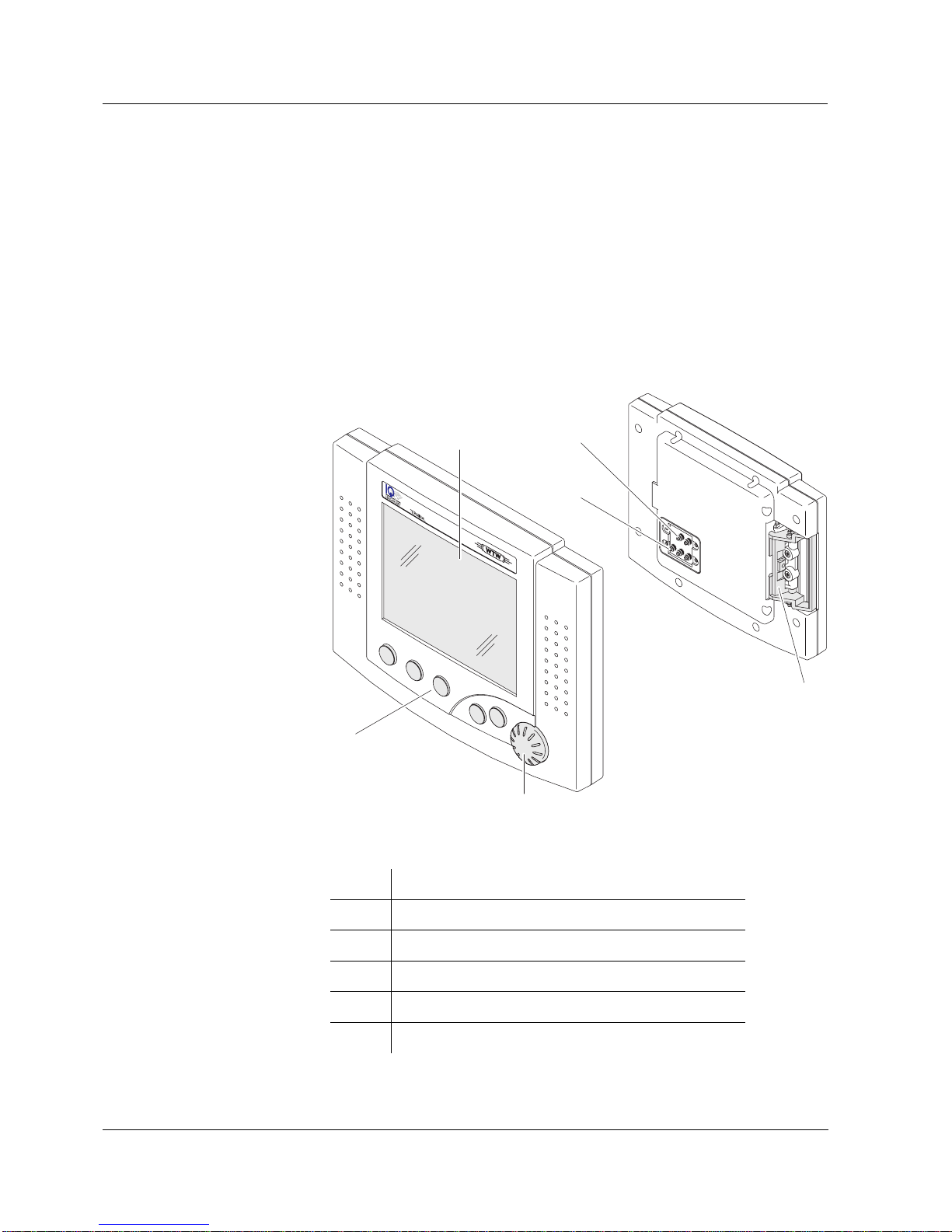
1.2 Terminal function of the MIQ/T2020 PLUS . . . . . . . . . . 1-1
1.3 MIQ/T2020 PLUS controller operation . . . . . . . . . . . . . .1-3
2 Safety instructions . . . . . . . . . . . . . . . . . . . . . . . . . . . . 2-1
2.1 Authorized use . . . . . . . . . . . . . . . . . . . . . . . . . . . . . . . . 2-2
2.2 General safety instructions . . . . . . . . . . . . . . . . . . . . . . . 2-2
3 Installation . . . . . . . . . . . . . . . . . . . . . . . . . . . . . . . . . . 3-1
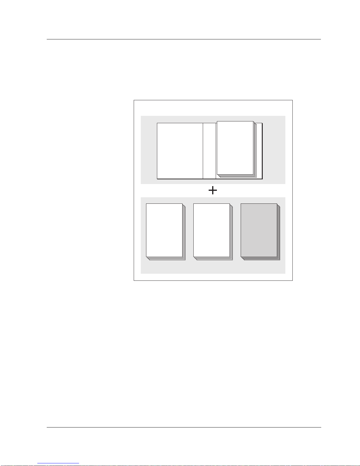
3.1 Scope of delivery . . . . . . . . . . . . . . . . . . . . . . . . . . . . . .3-1
3.2 Commissioning . . . . . . . . . . . . . . . . . . . . . . . . . . . . . . . . 3-1
3.2.1 Software requirements . . . . . . . . . . . . . . . . . . .3-1
3.2.2 Docking and removing a terminal . . . . . . . . . . . 3-1
3.2.3 Initialization . . . . . . . . . . . . . . . . . . . . . . . . . . . .3-3
4 Operation . . . . . . . . . . . . . . . . . . . . . . . . . . . . . . . . . . . 4-1
4.1 Introduction . . . . . . . . . . . . . . . . . . . . . . . . . . . . . . . . . .4-1
4.1.1 Overview of the operating elements . . . . . . . . .4-2
4.1.2 Display . . . . . . . . . . . . . . . . . . . . . . . . . . . . . . .4-3
4.1.3 Keys . . . . . . . . . . . . . . . . . . . . . . . . . . . . . . . . . 4-5
4.1.4 Rotary switch . . . . . . . . . . . . . . . . . . . . . . . . . . . 4-5
4.2 General operating principles . . . . . . . . . . . . . . . . . . . . .4-6
4.2.1 Navigating in menus, lists and tables . . . . . . . .4-7
4.2.2 Entering text or numerical values . . . . . . . . . . .4-8
4.3 MIQ/T2020 PLUS controller operation . . . . . . . . . . . . .4-10
4.3.1 General information . . . . . . . . . . . . . . . . . . . . . 4-10
4.3.2 Saving the system configuration manually . . .4-13
4.3.3 Retransferring the system configuration . . . . .4-14
4.4 Software status . . . . . . . . . . . . . . . . . . . . . . . . . . . . . . 4-15
5 Settings/Setup . . . . . . . . . . . . . . . . . . . . . . . . . . . . . . . 5-1
5.1 Selecting the language . . . . . . . . . . . . . . . . . . . . . . . . . .5-1
5.2 Terminal settings . . . . . . . . . . . . . . . . . . . . . . . . . . . . . .5-2
6 Maintenance and cleaning . . . . . . . . . . . . . . . . . . . . . 6-1
6.1 Maintenance . . . . . . . . . . . . . . . . . . . . . . . . . . . . . . . . . . 6-1
6.2 Cleaning . . . . . . . . . . . . . . . . . . . . . . . . . . . . . . . . . . . . .6-1
7 Technical data . . . . . . . . . . . . . . . . . . . . . . . . . . . . . . . 7-1

Contents IQ SENSOR NET MIQ/T2020 PLUS
0 - 2

IQ SENSOR NET MIQ/T2020 PLUS Overview
1 - 1
1Overview
1.1 How to use this component operating manual
Structure of the
IQ SENSOR NET
operating manual
Fig. 1-1 Structure of the IQ SENSOR NET operating manual
The IQ SENSOR NET operating manual has a modular structure like the
IQ SENSOR NET itself. Itconsists of a system operating manualand the
operating manuals of all the components used.
Please file this component operating manual into the ring binder of the
system operating manual.
1.2 Terminal function of the MIQ/T2020 PLUS
The MIQ/T2020 PLUS terminal is an extension component for the
IQ SENSOR NET system.Itcanbedockedon– and removed again from
– any free lid front of an MIQ module as a mobile control unit. The
docking is performed by a simple manual action without the need for
any tools.
IQ Sensor Net Operating Manual
System
Operating
Manual
(Ring Binder)
IQ Sensor
Operating
Manual
MIQ Module
Operating
Manual
MIQ Terminal
Operating
Manual
Component Operating Manuals

Overview IQ SENSOR NET MIQ/T2020 PLUS
1 - 2
Informationthatdescribesthebehavioroftheterminalafterthedocking
maneuver can be stored in each MIQ module. This information
includes:
lThe name of the respective measurement location
lA selection of measured values that should be displayed at this
measurement location.
This function (local identity function) can be used, e.g. to quickly find
sensorsforcalibrationonsite.Theinformationistransmittedbythetwo
upper contacts on the back of the terminal.
Fig. 1-2 MIQ/T2020 PLUS terminal
1Graphical display
2Keys
3Rotary switch
4Contacts for voltage and communication
5Contacts for the local identity function
6Docking mechanism
C
MS
ESC OK
MIQ/T2020 PLUS
1
2
3
5
4
6
Front
Back

IQ SENSOR NET MIQ/T2020 PLUS Overview
1 - 3
1.3 MIQ/T2020 PLUS controller operation
Automatic safety
function The MIQ/T2020 PLUS has a controller that takes over the basic
functions of the IQ SENSOR NET controller if it fails and thus
considerably increases the operational safety of the system. For this
purpose, the MIQ/T2020 PLUS automatically and regularly saves the
system configuration during the regular terminal operation.
System configuration Thesystemconfigurationcontainstheallocationofthesensornumbers
and all settings of the following menus:
lSettings of sensors and diff. sensors
lSettings of outputs and links
lEdit list of sensors
lEdit list of outputs
lMeasured value recording (datalogger settings).
In the IQ SENSOR NET, the system configuration is saved in the
controller (MIQ/C184 or MIQ/MC).
Functions in the MIQ/
T2020 PLUS controller
operation
The MIQ/T2020 PLUS controller operation comprises all basic
functions of the IQ SENSOR NET. Relay and current interfaces work
without restrictions.
Restrictions in the MIQ/
T2020 PLUS controller
operation
In the MIQ/T2020 PLUS controller operation, the following functions
cannot be supported:
lEditing the system configuration. Apart from date and time, all
settings in the Settings menu are locked and cannot be released for
changing
lAdding new sensors and input or output modules
lContinuing the datalogger operation of the main controller
lContinuing the Profibus, Modbus, or modem communication of the
main controller (due to missing interfaces).
A redundant data logging function can be set up with the aid of the
MIQ/IF232 interface module.
Manual saving function Apart from automatically saving the system configuration, the system
configuration can be saved manually in the MIQ/T2020 PLUS at any
timeduringregularterminaloperation.Thisfunctioncanbeusedforthe
MIQ/T2020 PLUS controller operation and for the following tasks as
well:
lMaking a safety copy of the system configuration, for example
before changing settings that may have to be undone again (testing
new settings).
lTransmitting the system configuration to a second IQ SENSOR NET
system. This facilitates the quick commissioning of several similar
systems.

Overview IQ SENSOR NET MIQ/T2020 PLUS
1 - 4

IQ SENSOR NET MIQ/T2020 PLUS Safety instructions
2 - 1
2 Safety instructions
This operating manual contains special instructions that must be
followed during the installation of the MIQ/T2020 PLUS. Thus, it is
essential for the operator to read this component operating manual
beforecarryingoutany workwiththesystem.Inadditiontothismanual,
the SAFETY chapter of the IQ SENSOR NET system operating manual
must be followed.
Always keep this component operating manual together with the
system operating manual and all other component operating manuals
in the vicinity of the IQ SENSOR NET system.
General safety
instructions The following safety labels in the individual chapters of this operating
manual indicate different levels of danger:
Warning
indicatesinstructionsthatmustbe followedpreciselyinordertoprevent
serious danger to personnel.
Caution
indicates instructions that must be followed precisely in order to avoid
slight injuries to personnel or damage to the instrument or the
environment.
Other labels
Note
indicates notes that draw your attention to special features.
Note
indicates cross-references to other documents, e.g. operating
manuals.

Safety instructions IQ SENSOR NET MIQ/T2020 PLUS
2 - 2
2.1 Authorized use
The authorized use of the MIQ/T2020 PLUS consists of its use as a
control unit with redundant controller function in the IQ SENSOR NET.
Please adhere to the technical specifications given in chapter 7
TECHNICAL DATA. Only operation according to the instructions in this
operating manual is authorized.
Any other use is considered to be unauthorized. Unauthorized use
invalidates any claims with regard to the guarantee.
2.2 General safety instructions
The MIQ/T2020 PLUS is constructed and inspected according to the
relevant guidelines and norms for electronic instruments (see chapter
7 TECHNICAL DATA).
It left the factory in a safe and secure technical condition.
Function and
operational safety The failure-free function and operational safety of the MIQ/
T2020 PLUS is only guaranteed if the generally applicable safety
measures and the special safety instructions in this operating manual
are followed during its use.
The failure-free function and operational safety of the MIQ/
T2020 PLUS is only guaranteed under the environmental conditions
that are specified in chapter 7 TECHNICAL DATA.
Safe operation If safe operation is no longer possible, the MIQ/T2020 PLUS must be
taken out of operation and secured against inadvertent operation.
Safe operation is no longer possible if the MIQ/T2020 PLUS:
lhas been damaged in transport
lhas been stored under adverse conditions for a lengthy period of
time
lis visibly damaged
lno longer operates as described in this manual.
If you are in any doubt, contact the supplier of your MIQ/T2020 PLUS.

IQ SENSOR NET MIQ/T2020 PLUS Installation
3 - 1
3 Installation
3.1 Scope of delivery
lMIQ/T2020 PLUS terminal
lOperating Manual
3.2 Commissioning
Note
Follow the installation instructions in the INSTALLATION chapter of the
system operating manual.
Up to three terminalcomponents can be docked on an IQ SENSOR NET
system.
3.2.1 Software requirements
The MIQ/T2020 PLUS requires for its operation an IQ SENSOR NET
main controller with the software version 2.04 or higher. Full
functionality is available when using a main controller with the software
version 2.70 or higher. Using older main controller versions there are
small functional restrictions when retransferring the storedsettings (for
details, see section 4.3.3).
3.2.2 Docking and removing a terminal
The mobile MIQ/T2020 PLUS terminal is docked on the lid of any free
MIQ module. The terminal can be docked while the system is running
without the measurement being interrupted.
Docking the terminal
Fig. 3-1 Preparing the MIQ module for docking
1

Installation IQ SENSOR NET MIQ/T2020 PLUS
3 - 2
Note
For the temporary docking of a mobile terminal, do not remove the
whole contact cover. Leave it hanging on the side of the MIQ module.
After removing the terminal, replace the cover again to protect the
contacts.
Fig. 3-2 Docking the terminal
Removing the terminal To remove the terminal, press the locking lever and pull the terminal
forwards.
1Pull the cover off the contacts (pos. 1 in Fig. 3-1) on the lid of
the MIQ module.
2Place the terminal on the module lid. To do so, insert the flap
on the back of the terminalinto the slot on thedoor hinge ofthe
module. Then, pull back the interlocking lever (pos. 2 in
Fig. 3-2), place the terminal completely on the module and
release the interlocking lever.
2

IQ SENSOR NET MIQ/T2020 PLUS Installation
3 - 3
3.2.3 Initialization
When the system is running, the terminal automatically starts to
operate as soon as contactis established to the IQ SENSOR NET. In the
first phase, the background illumination of the display switches on and
the terminal is initialized. This process may last a few seconds. The
following display appears (Fig. 3-3):
Fig. 3-3 Display during the initialization process
The terminal then switches to the measured value display.

Installation IQ SENSOR NET MIQ/T2020 PLUS
3 - 4

IQ SENSOR NET MIQ/T2020 PLUS Operation
4 - 1
4 Operation
4.1 Introduction
The MIQ/T2020 PLUS terminal is a control unit for the IQ SENSOR NET.
The terminal can be used to:
lDisplay measured values
lStart calibration
lPerform system and terminal settings
lDisplay messages.
Note
To guarantee data safety within the IQ SENSOR NET, access to the
following functions is only possible from one terminal at the same time:
lOpening the Settings menu
lStarting calibration
lAssigning sensors or output modules as substitutes.
If one of these functions is already active at another terminal, a note
appears on the display.

Operation IQ SENSOR NET MIQ/T2020 PLUS
4 - 2
4.1.1 Overview of the operating elements
This section gives basic informationon the operation of the IQ SENSOR
NET system via the MIQ/T2020 PLUS.
The terminal is equipped with a large display for the clear presentation
of current measured values, the graph of measured values, status
displays and message texts.
The IQ SENSOR NET system is operated using the 5 keys
m,c,s,e,gand the rotary switch d.
Fig. 4-1 View of the MIQ/T2020 PLUS terminal
1Display (see section 4.1.2 DISPLAY)
2Rotary switch (see section 4.1.4 ROTARY SWITCH)
35 keys m,c,s,e,g(see section 4.1.3 KEYS)
1
32
C
MSESC OK
MIQ/T2020 PLUS
TERMINAL

IQ SENSOR NET MIQ/T2020 PLUS Operation
4 - 3
4.1.2 Display
The display contains the following information:
Fig. 4-2 View of the display
1Name of the display
2Name of the terminal and instrument designation (display
changes in cycles of 5 s)
3Date
4Time
5Lock safety setting:
aopen (settings released)
–System settings can be changed
zclosed (settings locked)
–All system settings can only be read
6Error symbol h:
If the error symbol flashes, a new or unacknowledged error
message is present in the log book.
7Info symbol i:
If the info symbol flashes, a new or unacknowledged error
message is present in the log book.
8Number of the display
9Display range for measured values, menus, lists, etc.
10 Help line with operating instructions
2345 7
18
9
6
10

Operation IQ SENSOR NET MIQ/T2020 PLUS
4 - 4
Note
A detailed description of the log book is given in the IQ SENSOR NET
system operating manual.
Measured value display Themeasuredvaluedisplaycontainsthefollowinginformationforeach
sensor/differential sensor:
Fig. 4-3 Display - measured value display
1Consecutive numbering of the measured values
2Main measured value
3Unit and parameter of the main measured value
4Name of the sensor
5Secondary measured value with unit, e.g. temperature
1 2345

IQ SENSOR NET MIQ/T2020 PLUS Operation
4 - 5
Special displays
4.1.3 Keys
4.1.4 Rotary switch
Init Sensor is being initialized
lduring commissioning or
lif a new sensor is identified and this does not yet
provide any measured values
Set Sensor is being set
Cal Sensor is being calibrated
---- Invalid measured value, or defective sensor
Error Communication with sensor interrupted
OFL Measuring range undercut or exceeded (overflow)
Clean The time-controlled sensor cleaning function is active
(see MIQ/CR3 operating manual).
Display
flashes Sensor in maintenance condition
Key Function
mDisplay measured values
cStart calibration
of the sensor selected in the measured value display
sOpen the Settings menu
eChange to the higher menu levels or
abort entries without storing them
gConfirm selection
Rotary
switch Function
dHighlight and select:
lMenu items
lEntries
lColumns or fields
lLetters or numerals

Operation IQ SENSOR NET MIQ/T2020 PLUS
4 - 6
Note
The selection highlighted with the rotary switch is displayed as white
text on a black background (reverse video).
4.2 General operating principles
The operation of the IQ SENSOR NET is standardized and user-friendly.
lMake a selection with the rotary switch d
–Highlight individual elements in menus, lists and tables, e.g.
menu entries, list elements, columns or fields
–Select a setting in selection fields
–Select a character in text entry fields
lConfirm a selection with the gkey.
lBreak off an action and change to the next higher level with the e
key.
lStart a calibration procedure with the ckey.
lSwitch to the settings with the skey.
lChange to the measured value display and break off current actions
with the mkey.
Note
Short operating instructions are given in the help lines on the display.
Examples of the operating principles are given below:
lNavigation in menus, lists and tables (see chapter 4.2.1)
lEntering text and numerical values (see chapter 4.2.2)
Table of contents
Other wtw Touch Terminal manuals