manuals.online logo
Brands
  1. Home
  2. •
  3. Brands
  4. •
  5. Wunderbar
  6. •
  7. Dispenser
  8. •
  9. Wunderbar WB-MU-02-01 User manual

Wunderbar WB-MU-02-01 User manual

This manual suits for next models

3

Other Wunderbar Dispenser manuals

Wunderbar Mark 4 User manual

Wunderbar

Wunderbar Mark 4 User manual

Wunderbar WB-RT N Series User manual

Wunderbar

Wunderbar WB-RT N Series User manual

Wunderbar JoeTap NITCOM Operating instructions

Wunderbar

Wunderbar JoeTap NITCOM Operating instructions

Popular Dispenser manuals by other brands

BOWMAN CL003-0111 manual

BOWMAN

BOWMAN CL003-0111 manual

SIKA Power Cure operating instructions

SIKA

SIKA Power Cure operating instructions

Silver King Majestic SK12MAJ Technical manual and replacement parts list

Silver King

Silver King Majestic SK12MAJ Technical manual and replacement parts list

Franke F3Dn Twin Service manual

Franke

Franke F3Dn Twin Service manual

HURAKAN HKN-MT1 manual

HURAKAN

HURAKAN HKN-MT1 manual

STIEBEL ELTRON UltraHot Plus Operation and installation instructions

STIEBEL ELTRON

STIEBEL ELTRON UltraHot Plus Operation and installation instructions

Bobrick B-828 troubleshooting guide

Bobrick

Bobrick B-828 troubleshooting guide

DAN DRYER 282 installation guide

DAN DRYER

DAN DRYER 282 installation guide

Essity Tork 473208 manual

Essity

Essity Tork 473208 manual

CBS SD300BU-88 COMPONENT MAINTENANCE MANUAL WITH ILLUSTRATED PARTS LIST

CBS

CBS SD300BU-88 COMPONENT MAINTENANCE MANUAL WITH ILLUSTRATED PARTS LIST

Sealey MK77 manual

Sealey

Sealey MK77 manual

Fluid Management Accutinter 1600 End user guide

Fluid Management

Fluid Management Accutinter 1600 End user guide

Franke DVS SD99-010 Installation and operating instructions

Franke

Franke DVS SD99-010 Installation and operating instructions

Graco Dispensit 1053-10C operation & maintenance

Graco

Graco Dispensit 1053-10C operation & maintenance

DPR SED02 user manual

DPR

DPR SED02 user manual

ITALTINTO i50 user manual

ITALTINTO

ITALTINTO i50 user manual

Coca-Cola FREESTYLE 9000 user guide

Coca-Cola

Coca-Cola FREESTYLE 9000 user guide

Hewi 805.06.150 Mounting instructions

Hewi

Hewi 805.06.150 Mounting instructions

manuals.online logo
manuals.online logoBrands
  • About & Mission
  • Contact us
  • Privacy Policy
  • Terms and Conditions

Copyright 2025 Manuals.Online. All Rights Reserved.

CONTENTS PAGE NUMBER
Safety and Warnings / Sécurité et Avertissements……………………………. 2
Overview............................................................................................................. 3-4
Mustang Installation......................................................................................... 5-9
Mustang Operation........................................................................................... 10-11
Start-Up…………….…..…………………………………………………….………... 12-15
Sanitizing and Cleaning………………………………………………….…………. 16-17
Electrical Schematic…………………………………….…………………………… 18
Installation Schematics……………………………………………………………... 19-24
MUSTANG MANUAL.pub REV071519
Beverage Tower Dispenser
For Dispensers with model number
WB-MU-(A)-(B)-(1)-(2)
Wunder-Bar
Mustang Tower
(A) =01: Clamp with Front Display
02: Clamp with Front Display and Rear Display
03: Countertop Mount with Front Display
04: Countertop Mount with Front and Rear Display
(B) = 01: No Drain
02: Drain
(1) = Number of Post-Mix BASE Beverages (0 to 8)
(2) = Number of Flavor Concentrate Additives (0 to 8)
100-240 VAC, 50/60 Hz, 1.4A
ATTENTION
Unplug the Dispenser’s
power cord from the
electrical supply before
removing any covers, making
any adjustments, or
performing any service on
this dispenser.
™
2
ATTENTION!
This equipment is rated for indoor use only. It will not operate in sub-freezing
temperature. In a situation when temperatures drop below freezing, the equipment must
be turned off immediately and properly winterized.
Removal from Service/Winterization
GENERAL
Special precautions must be taken if the dispenser is to be removed from service for an
extended period of time or exposed to ambient temperatures of 32°F (0°C) or below.
CAUTION
If water or syrup is allowed to remain in the dispenser in freezing temperatures, severe
damage to some components could result. Damage of this nature is not covered by the
warranty.
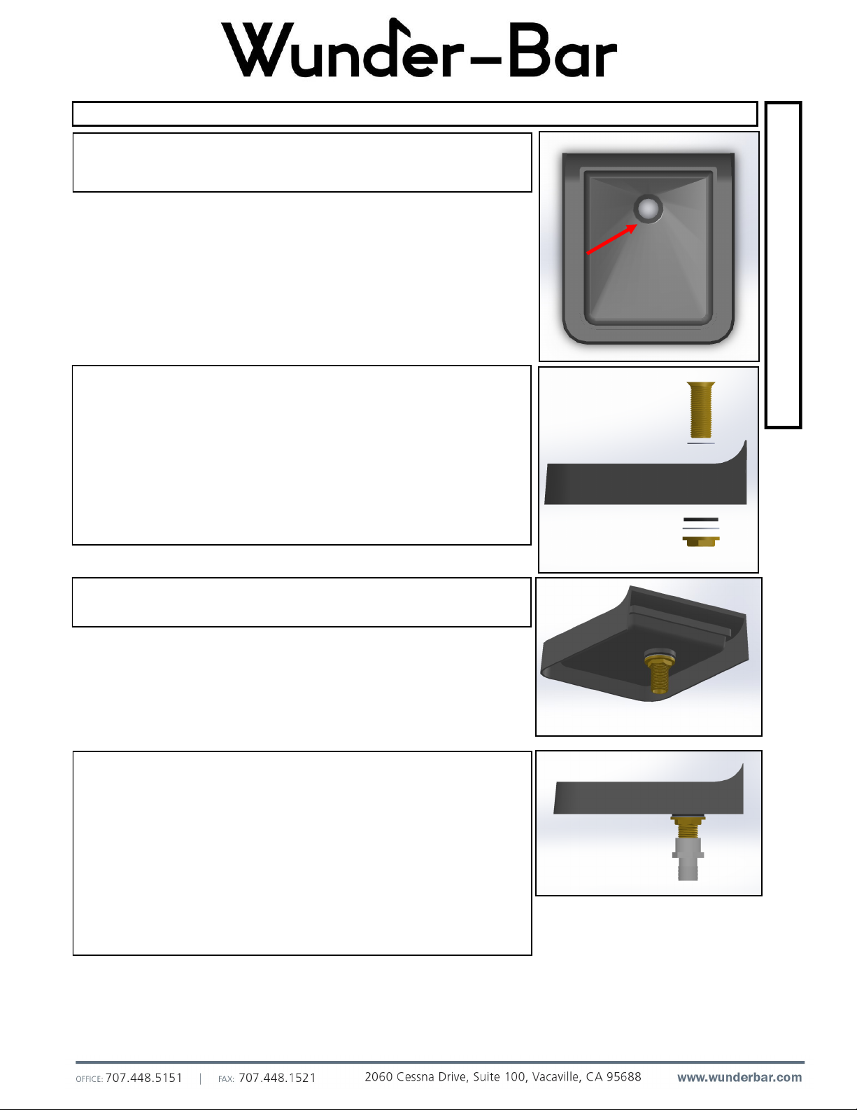
WINTERIZATION PROCEDURE
1. Turn off the water and all syrup supply.
2. Disconnect and drain the incoming water line at the rear of the dispenser.
3. Blow clean, dry compressed air into all incoming water/syrup inlets and the drain
openings in the bottom of the dispenser until no more water comes out the water/
syrup valves or drain.
4. Make sure no water or syrup is trapped in any of the water or syrup lines or drain
lines.
5. Disconnect the electric power at the circuit breaker or the electric service switch.
Cet équipement est conçu pour une utilisation en intérieur. Il ne sera pas fonctionner en
sous-température de congélation. Dans une situation où les températures descendent en
dessous de zéro, l'équipement doit être éteint immédiatement et correctement pour
l'hiver.
Retrait du service / Hivérisation
GENERAL
Des précautions particulières doivent être prises si le distributeur doit être retiré du
service pour une période de temps prolongée ou exposé à des températures ambiantes
de 32 ° F (0 ° C) ou au-dessous.
ATTENTION
Si l'eau est autorisé à rester dans le distributeur en températures de congélation, de
graves dommages dans une certaine composants pourraient en résulter. Les dommages
de cette nature est ne sont pas couverts par la garantie.
PROCÉDURE HIVÉRISATION
1. Fermez le robinet d'alimentation et tous sirop.
2. Débrancher et vidanger la ligne d'eau entrant à l'arrière du distributeur.
3. Souffler de l'air comprimé dans l'ensemble entrants eau/ sirop entrées et les
ouvertures de vidange dans le fond du distributeur jusqu'à ce que plus de l'eau sort
les vannes d'eau / sirop ou de drain.
4. Assurez-vous pas d'eau ou de sirop est pris au piège dans une les conduites d'eau
ou de sirop ou de lignes de drain.
5. Débranchez l'alimentation électrique au niveau du disjoncteur ou l'interrupteur de
service électrique.
™
• Read all Instructions before setting up or operating the dispenser.
• This dispenser is not to be used by persons (including children) with reduced physical, sensory, or mental capabilities, or lack of experience or knowledge, unless they have
been given supervision or instruction.
• Always disconnect the main power cord from the electrical source before removing any access panels or attempting to perform any servicing of this dispenser.
• Caution, Risk of Electric Shock. If the cord or plug becomes damaged, replace only with a cord and plug of the same type.
• Caution, Risk of Electric Shock. Do not operate the dispenser with a damaged power cord or if the equipment has been dropped or damaged—until it has been examined by
a qualified service person.
• The dispenser should never be cleaned using a water jet nor installed in an area where a water jet is used.
• Service access panels should be removed by qualified service technicians, ONLY.
• Access to the service areas of this dispenser is restricted to qualified technicians with safety/hygiene knowledge, experience, and training for servicing this specific dispenser.
• Install and use this dispenser only as described in this instruction manual. Use only the manufacturer’s recommended attachments.
• This dispenser should be operated in the ambient temperatures: MIN: 2° C, 36° F MAX: 40° C, 104° F
FCC Statement: This equipment has been tested and found to comply with the limits for a Class A digital device, pursuant to part 15 of the FCC Rules. These limits are designed to
provide reasonable protection against harmful interference when the equipment is operated in a commercial environment. This equipment generates, uses, and can radiate radio
frequency energy and, if not installed and used in accordance with the instruction manual, may cause harmful interference to radio communications. Operation of this equipment in a
residential area is likely to cause harmful interference in which case the user will be required to correct the interference at his own expense.
IC Statement: This device complies with Industry Canada license exempt RSS standard(s). Operation is subject to the following two conditions: (1) this device may not cause
interference, and (2) this device must accept any interference, including interference that may cause undesired operation of the device.
• Lire toutes les instructions avant d'installer ou d'utiliser le distributeur.
• Ce distributeur ne doit pas être utilisé par des personnes (y compris des enfants) ayant des capacités physiques, sensorielles ou mentales réduites ou un manque d'expérience
ou de connaissances, à moins d'avoir reçu une supervision ou des instructions.
• Toujours débrancher le cordon d'alimentation de la source électrique avant de retirer les panneaux d'accès ou de tenter d'effectuer toute intervention de ce distributeur.
• Attention, risque de choc électrique. Si le cordon ou la prise est endommagé, remplacer avec un cordon et la prise du même type.
• Ne pas faire fonctionner le distributeur avec un cordon d'alimentation endommagé ou si l'équipement a été échappé ou endommagé, jusqu'à ce qu'il ait été examiné par un
technicien qualifié.
• Le distributeur ne doit jamais être nettoyé avec un jet d'eau, ni installé dans une zone où un jet d'eau est utilisé.
• Panneaux d'accès aux services doivent être enlevés par des techniciens qualifiés, SEULEMENT.
• Accès aux zones de service de ce distributeur est limitée à des techniciens qualifiés de la sécurité / des connaissances d'hygiène, l'expérience et la formation pour l'entretien de
ce distributeur spécifique.
• Installer et utiliser ce distributeur tel que décrit dans ce manuel d'instruction. Utilisez uniquement du fabricant les accessoires recommandés par.
• Ce distributeur ne doit être utilisé dans les températures ambiantes: MIN: 2° C, 36° F MAX: 40° C, 104° F
IC Déclaration: Le présent appareil est conforme aux CNR d’Industrie Canada applicables aux appareils radio exempts de licence. L’exploitation est autorisée aux deus conditions
suivantes : (1) l’appareil ne doit pas produire de brouillage, et (2) l’appareil doit accepter tout brouillage radioélectrique subi, même si le brouillage est susceptible d’en compromettre
le fonctionnement.
3
™
O
V
E
R
V
I
E
W
The Mustang Tower can be configured to
dispense 6 carbonated post-mix beverages, 2
non-carbonated beverages (tap water,
carbonated water) and 2 Flavor Shots.
Typical installation will have the Mustang coun-
ter-mounted with BIB Pumps and BIB storage
rack located in the immediate area, such as, in
the cabinet below or adjacent to the tower.
IMPORTANT!
CARB & NON-CARB BEVERAGE APPLICATIONS:
POTABLE WATER SUPPLY:
Locate an existing potable water source with
shut-off valve or have a licensed plumber install
shut-off valve with 3/8” connection.
BACKFLOW PREVENTION REQUIRED!
Water pipe connections and fixtures directly
connected to a potable water supply shall be
sized, installed and maintained in accordance
with federal, state, and local codes.
This beverage dispenser’s water supply
line must be connected to the potable
water supply with adequate backflow
prevention to comply with federal, state,
and local codes.
GENERAL SPECIFICATIONS:
Inlet Water Pressure: Dynamic Water Pressure Range:
25 to 95 PSI / 0.17 to 0.62 MPa
Maximum Static Pressure:
100 PSI/ 0.69 MPa
Primary Voltage: 100V~ .19A / 240V~ 1.4A 50/60 Hz
Secondary Voltage: 12 VDC, 8.5 A
Dimensions:
Model A: 8.00” W x 13.50” D x 16.00” H
(Countertop) 20.32 cm W x 34.29 cm x 40.64 cm H
Model B: 8.00” W x 13.00” D x 21.25” H
(Clamp) 20.32 cm W x 33.02 cm D x 53.98 cm H
Models A&D: 8.00” W x 13.50” D x 16.75” H
(Countertop w/ Rear Display) 20.32 cm W x 34.29 cm x 42.55 cm H
Models B&D: 8.00” W x 13.00” D x 22.00” H
(Clamp w/ Rear Display) 20.32 cm W x 33.02 cm D x 55.88 cm H
Shipping Weight: 35 Pounds / 15 Kilograms
TOWERS WITH REAR DISPLAY
WB-MU-02-01 (BAR CLAMP W/ REAR DISPLAY)
WB-MU-04-01 (COUNTERTOP W/ REAR DISPLAY)
02-01 04-01
BASE TOWERS
WB-MU-03-01 (COUNTERTOP)
WB-MU-01-01 (BAR CLAMP)
01-0103-01
4
TOOLS REQUIRED:
 #2 Phillips screwdriver
 Oetiker clamp crimping tool
 Power drill
 Drill Bits (Size I, #29, 1 3/8” Step, Size F, 53/64”)
 Keyhole Saw
 Brix Cup and 200 ml graduated cylinder
 Cup or pitcher
 Deburring Tool
O
V
E
R
V
I
E
W
PRE-INSTALLATION PLANNING
GENERAL:
Determine and confirm the appropriate location for mount-
ing the Mustang Tower with the store manager. Typically,
this will be the same location where all other soft-drink
and beverage dispensers are located.
MUSTANG TOWER WITH DRAIN FITTING:
Ensure that the drain hose assembly is within distance of
a drain according to federal, state, and local codes and
regulations.
BIB RACK LOCATION:
Determine where the BIB rack is located, if one already
exists. If a BIB Rack does not exist, work with the
manager to determine the optimal location for the new BIB
Rack.
UNDER COUNTER (Fig.1):
Taking available space into account, locate the BIB
Pumps and Rack in cabinetry directly below the Mustang
Tower. Confirm that there is enough space available for a
rack capable of holding 8 BIB containers.
ADJACENT ROOM OR STORE ROOM (Fig.2):
In most cases under counter storage space will not be
available and the BIB Pumps and Rack storage rack must
be located remotely, such as: in the next room or in a
remote storage area, next to any existing soft-drink BIB
Rack, if one exists. Run the syrup line bundle as
appropriate according to federal, state, and local codes
and regulations.
™
Fig. 1
Fig. 2
ELECTRICAL INFORMATION:
-For a part of class III construction supplied from a detacha-
ble power supply unit, the instructions state that the appli-
ance is only to be used with the unit provide.
-Instructions for class III appliances state that it must only
be supplied at SELV.
5
I
N
S
T
A
L
L
A
T
I
O
N
1. Use the included drilling template to mark the Mustang Tower’s five
(5) mounting holes, drain hole, and tubing exit port onto the
countertop surface. (Fig. 3)
NOTE: Maximum countertop thickness is 2”.
2. Drill out the mounting holes using the Size F drill-bit. To cut-out the
tubing exit port, use a keyhole saw.
3. If installing a unit with a drain, use a #29 drill bit to create a pilot hole
for the drain hole.
4. Install the provided fittings onto the appropriate syrup tubing using
the provided Oetiker’s Clamp.
5. Prior to installing the Mustang Tower onto the counter, insert the
provided recirculation bundle into the appropriate ports (soda and
water). Then, install the fittings and tubes from the previous step into
the Mustang Tower.
INSTALLING A MUSTANG TO A COUNTERTOP: CONFIG. –03-XX and –04-XX
™
TEMPLATE
5. Next, screw in the provided 1/4”-20 studs into the three (3) acetal
rods and the two (2) threaded inserts on the bottom side of the
Mustang Tower.
6. To mount the Mustang Tower to the counter, align the five (5) studs
on the bottom of the Mustang with the five (5) drilled-out holes in the
Countertop. While lowering the Mustang, make sure the tubes are
lined up and do not cross each other. (Fig. 4)
7. Secure the Mustang Tower in place with the included hardware: 1/4
Washers and 1/4-20 Nuts.
8. Take the provided 1/4” Wire Loom (Wunder-Bar p/n MU-5K) and cut
to appropriate length to cover any exposed threads. Cut any excess
loom. (Fig. 5)
9. Connect the water and syrup lines.
Fig. 3
Fig. 4
Fig. 5
6
I
N
S
T
A
L
L
A
T
I
O
N
1. The bar clamp versions of the Mustang Tower do not require any
cutting into an existing bar top. They are designed to clamp onto the
front of a bar top.
NOTE: Maximum countertop thickness is 4”.
2. Pre-install the provided input fittings onto the appropriately
lengthened tubing. Then, install them into the Mustang Tower. Also,
install the recirculation bundle to the appropriate ports (carbonated
water and still water).
CLAMPING A MUSTANG TO A BAR TOP— CONFIG. –01-XX and –02-XX
™
3. Slide the Mustang Tower onto the front of the bar and tighten the
bar-clamp by turning the knobs. Tighten until the Mustang Tower is
fully mounted. (Fig 7)
4. Be careful to not overtighten the unit. If the tower starts to tilt
forwards, then you have overtightened the unit.
5. Connect the water and syrup lines.
6. Take the provided 3/8” Wire Loom (Wunder-Bar p/n MU-3R-1) and
cut them to length to cover the threaded rods so that they are not
exposed. Make sure both sides of the threaded rods are covered.
Fig. 7
Fig. 6
7
I
N
S
T
A
L
L
A
T
I
O
N
1. The rear display can be attached to either base
configuration and is sold as an add-on.
2. Unplug the power to the unit.
3. Remove the four (4) 6-32 screws securing the
Rear Cover onto the Mustang Tower and the two
(2) 4-40 screws near the Display Head. Set aside.
Remove the four (4) 6-32 screws securing the
Front Cover. Set aside.
4. Drill two holes using the size “I” drill bit at the two
dimples closest to the flat portion of the rear cover
on the inside of the cover.
5. Drill two (2) more holes using the #29 drill bit at the
remaining two dimples on the cover.
6. Then, drill a hole at the square using a 1 3/8” step
drill bit.
ATTACHING THE REAR DISPLAY— CONFIG. -02-XX AND –04-XX
™
7. The finished part should look like Fig. 9. Deburr all drilled holes.
8. Fish the end of the USB cable and the green power cable coming from the Rear Display Assembly
through the 1 3/8” hole so that the cables will be inside the unit. (Fig. 10)
9. Line up the two bosses on the Rear Display Assembly with the two larger holes on the Rear Cover. Press
them into the holes. The screen should be parallel with the flat surface on the Rear Cover.
10. Secure using the provided four (4) #4 washers and the four (4) #4-20 screws. Tighten until the Rear
Assembly is flush with the back cover. (Fig. 11)
Fig. 9
Fig. 10
Fig. 11
Size “I”
Drill Bit
1 3/8” Step
Drill Bit
#29 Drill
Bit
Fig. 8
8
I
N
S
T
A
L
L
A
T
I
O
N
11. Connect the green connector with the label “Rear Display” with the green port on the display of the Rear
Assembly. (Fig. 12)
12. Fish the end of the USB through the front of the solenoids, then down the slot on the bottom of the
housing the same way the power cord and the Front Display USB are done. (Fig. 13 and 14)
ATTACHING THE REAR DISPLAY— CONFIG. –02-XX AND –04-XX
™
13. Re-attach the Rear Cover by tucking it underneath the tab of the Front Display. Secure using the screws
previously set aside. (Fig. 15).
14. Re-attach the Front Cover using the screws previously set aside.
15. The Rear Display should look like Figure 16 after installation is complete. Ensure the connections are
working properly by plugging in the power .
Fig. 12
Fig. 13
Fig. 14
Fig. 15
Fig. 16
9
I
N
S
T
A
L
L
A
T
I
O
N
1. The drain feature can be attached to either configuration.
2. Set the Drip Tray Basin down. Drill a hole using a 53/64” size drill bit
at the center of the countersunk portion. See Figure 17.
ATTACHING THE DRAIN FITTING — CONFIG. XX-02
Fig. 18
Fig. 19
Fig. 20
Fig. 17
3. Unscrew the nut from the provided drain fitting and remove the
metal washer and the rubber washer. Leave the white plastic
washer on.
4. Slide the provided drain fitting through the hole so that the white
washer will be sandwiched between the bottom of the drain fitting
head and the basin. See Figure 18 for the exploded view of the
drain fitting and its parts.
5. Slide the rubber washer over the threaded part of the fitting. Then,
slide the metal washer over the threaded part of the fitting. Tighten
with the provided nut until the washers are sandwiched up against
the drain fitting. See Figure 18 for the correct order of parts.
6. The drain fitting should be tight on the drip basin. Figure 19 shows
the bottom view of the assembly.
7. Use RTV Silicone around the edges of the fitting where it meets with
the top-side of the basin to fill all the gaps. Let cure.
8. Screw on the provided 1/2” NPT to 3/4” Barbed Fitting. See Figure
20.
9. Attach the provided Drain Hose Assembly by sliding on the hose
clamp and sliding the hose over the barbed portion of the drain
fitting. Secure using the hose clamp.
10. For WB-MU-03-02 and WB-MU-04-02, place the drip tray basin into
the rim. Then, apply a small bead of RTV Silicone around the
bottom edge where the basin meets the countertop.
™
10
O
P
E
R
A
T
I
O
N
Normal operation mode:
1. Initialization
Connect the power supply harness to the power supply.
Do not touch any area of the Touchscreen during the Startup
Sequence.
2. Beverage dispensing (up to 8 Brands) for SELF-SERVE
A. The normal operating screen will look like Fig. 21.
B. Press any brand to enter the Dispense Beverage
Screen.
i. For systems without flavor additives: Press and hold
the brand button to dispense the selected beverage.
Release the brand button to stop dispensing the
selected beverage.
OPERATING STANDARD
™
C. Select and dispense the desired Beverage
i. For systems with flavor additives (not available on 8
Brand):
a. Select the desired flavor(s). More than one flavor
can be selected at a time (Fig. 23 shows both VA-
NILLA and STRAWBERRY being selected).
b. Press and hold the POUR button. Release to
POUR button to stop dispensing.
The programmable maximum Dispense interval is 30 seconds
(60 ounces).
Fig. 21
Fig. 22
Fig. 23