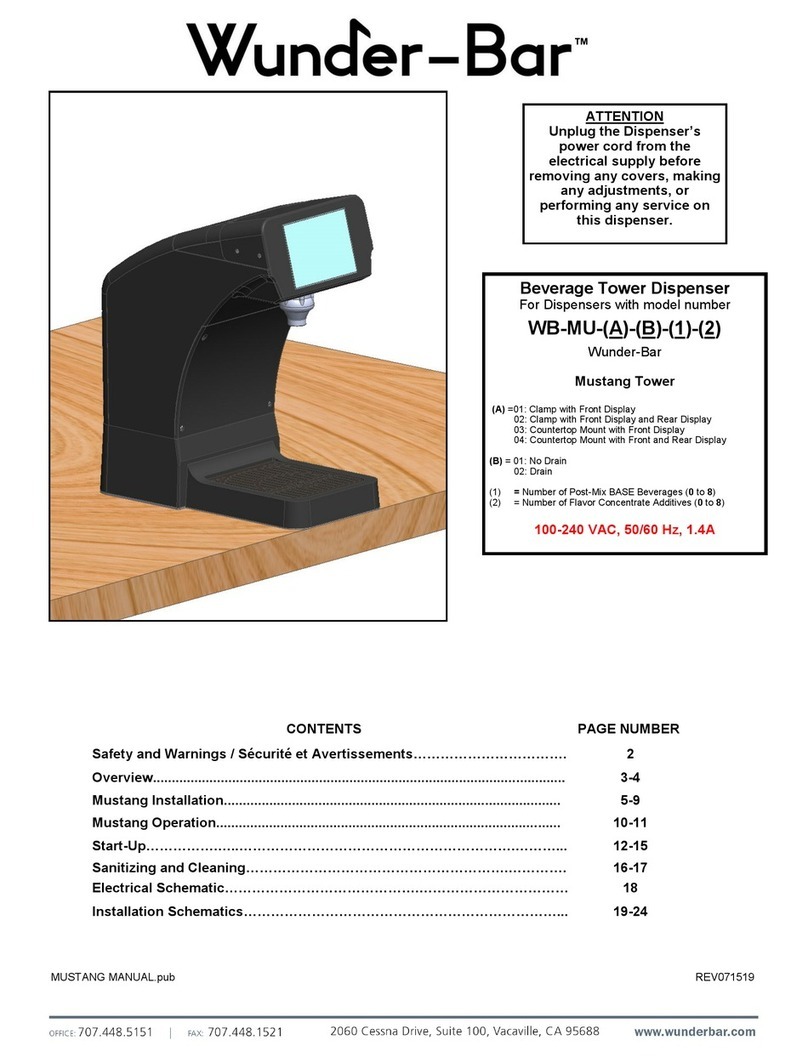
Wunderbar WB-RT N Series User manual

CONTENTS PAGE NUMBER
Overview............................................................................................................ 2-3
Operation........................................................................................................... 4
Installation......................................................................................................... 5–7
Start-up.............................................................................................................. 8–11
Optional Features……………………………………………………………….…... 12-14
Brand Card Sticker Replacement………………………………………………… 15
Troubleshooting…………………………………………………………….……….. 16
Sanitizing and Cleaning………………………………………………….…………. 17-18
Exploded Parts Drawing…………...…………………………………….…………. 19-21
Replacement Parts List ……………..……………………………………………... 22-24
TEA TOWER MANUAL RT-128.pub
Variety Tea Tower Dispenser
For Dispensers with model numbers:
WB-RT-x-N
WB-RT-x-P
WB-RT-x-N-(NDT,ADA,SADA )
WB-RT-x-P-(NDT,ADA,SADA )
Wunder-Bar - Round Tea Tower
x= Number of post-mix Teas dispensable (1 to 4)
N =Non-Portion Controlled
P= Portion Controlled
NDT = No Drip Tray
ADA = ADA Accessible Switchpack Equipped
SADA = Smart ADA Accessible Switchpack Equipped
120VAC .45A 60 Hz
ATTENTION
Unplug the Variety Tea Tower
Dispenser’s power cord from
the electrical supply before
removing any covers, making
any adjustments, or
performing any service on
this dispenser.
REV071816
32C
Meets the Requirements
for NSF/ANSI 372
™

2
O
V
E
R
V
I
E
W
The Variety Tea Tower dispenser can be configured to
dispense 1 to 4, non-carbonated, post-mix tea prod-
ucts.
Typical installation will have the tower counter mounted
with BIB Pumps and BIB storage rack located in the
immediate area, such as, in the cabinet below or adja-
cent to the tower.
Note: This equipment has been tested and found to com-
ply with the limits for a Class A digital device, pursuant
to part 15 of the FCC Rules. These limits are designed to
provide reasonable protection against harmful interfer-
ence when the equipment is operated in a commercial
environment. This equipment generates, uses, and can
radiate radio frequency energy and, if not installed and
used in accordance with the instruction manual, may
cause harmful interference to radio communications.
Operation of this equipment in a residential area is likely
to cause harmful interference in which case the user will
be required to correct the interference at his own ex-
pense.
Modifications not expressly approved by the manufactur-
er could void the user's authority to operate the equip-
ment under FCC rules.
POTABLE WATER SUPPLY:
Locate an existing potable water source with
shut-off valve or have a licensed plumber install
shut-off valve with 3/8” connection.
IMPORTANT:
Water pipe connections and fixtures directly
connected to a potable water supply shall be
sized, installed and maintained in accord-
ance with federal, state, and local codes.
The tea dispensing system water supply line
must be connected to the potable water sup-
ply with adequate backflow prevention to
comply with federal, state, and local codes.
Fig.1
Backflow
Preventer
or Air Gap
™

3
PRE-INSTALLATION PLANNING
Confirm the appropriate location for mounting the tower
with the store manager. Typically this will be the same
customer self-service location where all other soft-drink
and beverage dispensing tower equipment is located,
in the “front of the house”.
A. Determine the appropriate location for the tea
BIB pump and storage rack with store manager.
If at all possible, the tea BIB pumps and storage
rack should be located in cabinetry below the Varie-
ty Tea Tower dispenser (Fig.2).
In some instances, where under-cabinet storage
space is not available, the tea BIB Pumps and stor-
age rack will be located in a remotely, such as, next
to the soft-drink BIB pump and storage rack loca-
tion.
B. If the BIB pump and storage rack must be
remotely located, determine the method for
running the syrup bundle overhead from the BIB
pumps to the Tea Tower.
If running through the ceiling, hangers must be
used to secure the tubing to the ceiling so tubing
does not lay on ceiling tiles.
If installing in a chase, the same process is used to
pull bundle tubing as stainless steel.
If running through walls, be careful not to cut
through fire walls or damage any plumbing or elec-
trical systems hidden in the wall(s) Fig.3).
O
V
E
R
V
I
E
W
Fig.2
Fig.3
GENERAL SPECIFICATIONS:
Inlet Water Pressure: 25 to 90 PSI dynamic water pressure
range
Water Reducer Valve: 50 PSI Water Pressure Reducer Valve
included with integral water inlet
pigtail assembly (see Fig. 7a, 7b, page 5)
Primary Voltage: 120 VAC via 8-foot long cord with 3-prong,
NEMA 5-15P grounded plug
Secondary Voltage: Internal power supply is 120 VAC Prima- 5A In-line Fuse
CCPN 114897 2.5A Power Supply
Fuse CCPN 115007
™

4
O
P
E
R
A
T
I
O
N
TO DISPENSE TEA:
FIRST: Position a cup under the nozzle.
(TOUCH FLAVOR light is flashing, Fig.A)
SECOND: Select the desired brand of Tea.
(The brand indicator is lit, Fig.B)
THIRD: Depress and hold the Dispense
Lever until the cup is full (Fig.C).
Release the Dispense Lever.
TOP-OFF:The brand selection will remain
active for 5 seconds after the
dispense. To “Top-Off” the
dispense, depress and hold the
Dispense Lever until the cup is full.
If the brand indicator is no longer
illuminated green, repeat steps
SECOND and THIRD, then TOP-OFF.
Fig.A
Fig.B
Fig.C
™

5
Fig.6
Fig.8
D C B A WATER
Splash
Plate
Fig.4
MAKE WATER CONNECTION
1. Connect 3/8” water line at water
source Shut-Off valve (Fig.6).
2. Connect the water source line to the
Reducer Valve’s 3/8” inlet fitting(Fig.7a).
The Water Pressure Reducer Valve
Pigtail (Fig,. 7a, 7b) must be installed.
3. Turn on water supply at the shut-off
valve and check for leaks. Turn off
the water shut-off valve when leak
checking is completed.
REMOTE BIB PUMP AND RACK NOTE:
Remote BIB Pump and Rack installa-
tions, requiring an overhead bundle
tubing run, may not allow through-the-
bottom access for the water and syrup
tubing. In those instances, mount the
tower, remove the rear tubing access
plug cap and route the water tubing
pigtail (with Reducer Valve) and syrup
tubing pigtails through the rear access
hole Fig.8) before making the water
line connection.
Fig.7a
Water Pressure
Reducer Valve
3/8” Barb Water Inlet
3/8” Line
Fig.5
Caulk
Fig.7b
I
N
S
T
A
L
L
A
T
I
O
N
MOUNTING THE TEA DISPENSER TOWER
The Dispenser will be typically mounted to one of the follow-
ing surfaces, next to existing self-serve soft-drink and other
beverage dispensers located at the “front of the house.”
On a laminated wood countertop, or
On a stainless steel countertop
Installing to a Countertop (Fig.4)
1.
Remove the Splash Plate (See Fig. A & B, C Page 9).
2. Position the tower in the desired countertop location
and mark the tubing access and tower mounting
holes (Fig.5).
3. Cut an access hole through the countertop for the
four (4) syrup and one (1) water tubing. (stainless
steel counters must be cut by an authorized
contractor).
4. Use a 9/32” to 5/16” drill bit to drill the mounting holes.
5. Place a 1/8” wide bead of silicone rubber caulk about
1/4” in from the edge, around the entire perimeter
of the tower base (Fig.5).
6. Use five (5) stainless steel 1/4” bolts and nuts to se-
cure the tower to a stainless steel countertop. Use
five (5) wood screws to secure the tower to laminated
wood surfaces.
7. Smooth the silicone caulk around the entire perimeter
of the tower base.
Fig.6
™

6
I
N
S
T
A
L
L
A
T
I
O
N
INSTALL SYRUP TUBING
The BIB Pumps and Rack will typically be located in the cabi-
net directly below or adjacent to the Variety Tea Tower (Fig.2,
page 3).
Four (4), 1-foot long, 3/8” braided syrup “pigtails”, with stag-
gered inlet fittings installed, are included with the Variety Tea
Tower. Remove Splash Plate (Fig, A, B, C Page 9).
UNDERCOUNTER PUMP AND BIB RACK:
1. Install the 4 syrup “pigtails” with staggered fittings into
the Manifold as shown in Fig.9, push the Kwik Klips in
to secure the fittings, and route the pigtails through
the Tower bottom as shown in Fig.10.
2. Install 3/8” barbed union fittings into each syrup
pigtail’s tube end and secure with a clamp.
3. Install each 3/8” syrup supply line onto the appropriate
pigtail’s barbed union and secure each with a clamp.
4. Re-install Splash Plate (See Fig. 24-26, page 11)
REMOTE PUMP AND BIB RACK—OVER CEILING:
1. Remove the plug from the rear tubing access hole (Fig.11).
2. Install the 4 Syrup “pigtails” with staggered fittings into
the Manifold as shown in Fig.9, push the Kwik Klips in
to secure the fittings, and route the pigtails through the
rear tubing access hole (Fig.11).
3. Install 3/8” barbed union fittings into each syrup pigtail’s
tube end and secure with a clamp.
4. Install each 3/8” syrup supply line onto the appropriate
pigtail’s barbed union and secure each with a clamp.
5. Re-install Splash Plate (See Fig. 24-26, page 11)
Fig.10
water Line
A
Line
B
Line
C
Line
D
Fig.9
water
Line
B
Line
C
Line
A
Line
D
Fig.11
Rear Plug
Rear Tubing
Access Hole
Water Pigtail
Water Pressure
Reducer Valve
Syrup Pigtails
D C B A WATER
ATTENTION
WATER PRESSURE REDUCING
VALVE PIGTAIL ASSEMBLY MUST BE
INSTALLED WHETHER OR NOT SYR-
UP PIGTAILS ARE UTILIZED.
™

7
Fig.12
Fig.13
Cap Plug for
drain access
I
N
S
T
A
L
L
A
T
I
O
N
INSTALL DRIP TRAY DRAIN
The Variety Tea Tower is shipped with a removable Drip Tray
(Fig.12) with a straight drain fitting installed.
REAR DRAINING DRAIN LINE INSTALLATION:
1. Lift and remove the drip pan from the tower front (Fig.12).
2. Remove black Cap Plug from lower tower skirt (Fig.13).
3. Attach the 1/2” ID gray drain line to the drip tray’s straight
drain fitting.
4. Carefully secure the gray drain line to the drain fitting using
either an Oetiker clamp or a screw clamp.
5. Route the gray drain line thru tower base and out the rear
tubing access hole, to the facility’s drain location. Mark the
drain line and cut to length.
6. Install drip pan to front of tower.
7. Pour water into the drip pan. Check the drain line to fitting
connection for leaks and confirm that the water flows freely
from the end of the drain line into the facility’s drain.
DOWNWARD DRAINING DRAIN LINE INSTALLATION:
1. Lift and remove the drip pan from the tower front (Fig.12).
2. Remove black Cap Plug from lower tower skirt (Fig.13).
3. Attach a 2” piece of 1/2” ID gray drain line to the drip tray’s
straight drain fitting.
4. Place two Oetiker or screw clamps onto the 2” gray drain
line attached to the drip tray. Crimp or tighten the clamps.
5. Attach a 1/2” x 1/2” 90° stainless steel elbow fitting to
the end of the 2” gray drain line.
6. Attach the remaining section of 1/2” ID gray drain line to the
1/2” x 1/2” 90° stainless steel elbow fitting.
7. Place an Oetiker or screw clamp onto the drain, at the 90°
stainless steel elbow fitting. Crimp or tighten the clamp.
8. Extend the 1/2” ID gray drain line to the facility’s drain.
9. Pour water into the drip pan. Check the drain line to fitting
connection for leaks and confirm that the water flows freely
from the end of the drain line into the facility’s drain.
NO DRAIN LINE:
1. Lift and remove the drip pan from the tower front (Fig.12).
2. Remove black Cap Plug from lower tower skirt (Fig.13).
3. Attach a 2” piece of 1/2” ID gray drain line to the drip tray’s
straight drain fitting.
4. Install a 1/2” plug (or new all-in-one plug CCPN 113754)
into the end of the 2” piece of 1/2” drain line.
5. Secure the drain line to the drain fitting and plug with two
Oetiker or screw clamps. Crimp or tighten the clamps.
Drain Fitting
™

8
Fig.19
Fig.20
Fig.21
START-UP
TO START DISPENSER:
1. Turn on water Supply. Check for water leaks.
2. Plug power cord into 110 Volt AC power outlet.
Touch Flavor LED should begin flashing
(Fig.19)
3. Turn on CO2 to BIB pumps. Check for syrup
leaks .
DISPENSE DRINKS
KEYPAD OPERATION:
With the “TOUCH FLAVOR” light flashing:
1. Position a cup under the nozzle.
2. Touch the desired brand key (Fig.20).
(brand light will illuminate and brand selection
will remain active for 5 seconds)
3. If incorrect brand is selected, press any
other brand to change the brand selection.
4. Depress and hold Dispense Lever until cup has
been filled to the desired level (Fig.21).
5. “Top Off” the dispense by depressing Dispense
Lever, again, within 5 seconds. If the brand
indicator is no longer illuminated green, repeat
steps SECOND and THIRD, then TOP-OFF.
S
T
A
R
T
U
P
™

9
S
T
A
R
T
U
P
SPECIFICATIONS
Finished Beverage Flow Rate:
2.0 ounces per second
Water Flow Rate: 1.69 oz/sec; 50 ml/sec
Syrup Flow Rate: .31 oz/sec; 9 ml/sec
Ratio Set Points: ALL BRANDS- 5.5:1
1. Remove the Splash Plate
A. Remove two Splash Plate
Phillips head retainer
Screws.
B. Grasp the bottom edge of
the Splash. Lift Splash
Plate upward 1/4”.
Fig.22
CALIBRATION
Fig.B Fig.CFig.A
C. Swing bottom of Splash Plate
outward. Then, pull down-
ward to remove Splash Plate
from tower.
TOOLS REQUIRED: PHILLIPS SCREWDRIVER
SLOT SCREWDRIVER
STANDARD RATIO CUP
50 or 100 ML GRADUATED
CYLINDER
Fig.21
TOUCH
FLAVOR
2.Simultaneously press and hold the A and B Brand Buttons (Fig.22). After 5 seconds, the
“TOUCH FLAVOR” light will flash RED indicating CALIBRATE MODE.
3. To Calibrate the Water: When in the default CALIBRATE MODE, only the “TOUCH FLAVOR”
light should be flashing RED, which will allow 4-second timed pours of water, only. DO NOT
PRESS ANY BRAND BUTTONS.
4. Place a Standard Ratio Cup under Nozzle and depress the Dispense Lever to start a 4-second dis-
pense of 6.8 Ounces (200 ml) of water ( when the twin water flow regulators are properly adjusted).
™

10
CALIBRATION (Continued)
5. If the amount of water dispensed is not 6.8 ounces (200 ml), loosen both water Lock Nuts (W in
Fig.23), and then use a flat blade screwdriver to adjust the water Flow Regulator Adjusting Screws
Clockwise to increase the amount of water dispensed or Counterclockwise to decrease the
amount of water dispensed.
6. Place Standard Ratio Cup under nozzle, depress Dispense Lever to confirm 6.8 oz (200 ml) of water.
7. To calibrate syrups: While still in the CALBRATE MODE, press the A, B, C, or D key to select
a syrup for calibration. The TOUCH FLAVOR light should be flashing RED and the selected syrup
light should be “ON”. (Pressing syrup key again returns system to the Water CALIBRATE MODE.)
8. Place 50 or 100 ml Graduated Cylinder under Nozzle.
9. Depress Dispense lever to initiate a 4-second dispense of the selected syrup.
10. Adjust the A, B, C, or D syrup Flow Regulator Adjusting Screw (Fig.23), if necessary. All syrups are
pre-set at the factory for a 5.5:1 ratio (1.23 oz , 36.4 ml, in 4 seconds). If the amount of syrup dis-
pensed is not 1.23 oz (36.4 ml), loosen the Lock Nut (Fig.23) and use a flat blade screwdriver to
adjust the appropriate Flow Regulator Adjusting Screw Clockwise to increase the amount of syrup
dispensed or Counterclockwise to decrease the amount of syrup dispensed.
11. Place 50 or 100 ml Graduated Cylinder under nozzle, depress Dispense Lever to confirm 1.23 oz
or 36.4 ml of syrup
12. REPEAT for all Brands.
13. Re-tighten all lock nuts (Fig.23)
14. Simultaneously press A and B Brand Buttons(Fig.21,22). After 5 seconds, the TOUCH FLAVOR will
resume flashing GREEN indicating return to NORMAL Mode.
15. Reinstall the Splash Shield (see Fig, 24, 25, 26 on page 11).
NOTE: Tea Dispenser will reset to normal “Ready to Dispense” mode if the Dispense Lever is not activated within 60
seconds after initiating the CALIBRATE mode.
Fig.22
S
T
A
R
T
U
P
Fig.23
SHUT-OFF SCREWS
(Vertical Slot = ON, Horizontal Slot = OFF)
Fig.21
TOUCH
FLAVOR
™

11
Fig.26
ADJUSTING SYRUP AMOUNTS FOR ALTERNATE RATIOS
4-Second dispense
4:1 = 1.69 oz (50 ml) 4.5:1 = 1.50 oz (44.5 ml) 5:1 = 1.35 oz (40 ml) 6:1 = 1.13 oz (33.4 ml)
Do Not Re-adjust the WATER from set-point of 1.69 oz/sec (50 ml/sec) or 6.76 oz (200 ml) in 4 Seconds
1. Remove the Splash Plate (Fig. A, B, C Page 9).
2. Simultaneously press A and B Brand Buttons (Fig.21 & 22, page 10). After 5 seconds, the “TOUCH
FLAVOR” light will flash RED indicating CALIBRATE MODE.
3. Place 50 or 100 ml Graduated Cylinder under Nozzle to recheck.
4. Press the desired brand key and then depress Dispense lever (a 4-second dispense will occur).
5. If the amount poured is less or more than the amount listed above, for a ratio other than 5.5:1,
adjust that brand’s Flow Regulator Adjusting Screw (Fig.23, page 10) Clockwise to increase the
amount of syrup dispensed or Counterclockwise to decrease amount of syrup.)
6. Repeat step 4 until the proper amount of syrup for the desired ratio, is dispensed in 4 seconds
7. Repeat steps 2 through 5 to adjust any other brands that require a ratio other than 5.5:1
8. Simultaneously press and hold the A and B Brand Buttons. After 5 seconds, the TOUCH FLAVOR
will resume flashing GREEN indicating return to NORMAL Mode.
9. Re-tighten all lock nuts (Fig.23, page 10)
10. Re-install the Splash Plate (Fig. 24, 25, 26)
A. Position both upper corners
of the Splash Plate inside
the opening flanges.
B. Slide Plate upward under
the overhang. Swing bottom
edge inward fully. Then
lower Splash Plate until
inner bottom clips are seat-
C. Install both Phillips head
Splash Plate retainer
screws and tighten, fully.
S
T
A
R
T
U
P
Fig.24 Fig.25 Fig.26
™

12
1. Disconnect Variety Tea Tower from AC power source.
2. Using Philips Screwdriver, remove Front Splash Plate and Top Cover.
3. Punch or cut small slot or thru-hole in Plug at the bottom rear of the Variety Tea Tower.
4. Route WIRE END of Switchpack Cable through Hole Plug and up through the slotted hole in the
Bulkhead Plate into Electronics Area.
5. Using the Short (slotted) Screwdriver, loosen all five screws of the ADA input Terminal trip (BLUE,
Fig.27)on the ADA CAPABLE CIU PCBoard.
6. Attach the Switchpack Cable Wire-ends to the ADA input Terminal Strip (Fig.28), as follows:
BLACK= GND; WHITE= 4; GREEN= 3; RED= 2; BROWN=1
Make sure all Screws of the Input Terminal Block are snug, but do not over-tighten.
7. Secure Switchpack Cable to the interior metal surface inside the electronics compartment, using the
adhesive-backed Tie Mount and Cable Tie included with kit.
DO NOT SECURE CABLE TO CIU PCBoard.
8. Reinstall Front and Top Access Covers.
9. Position and secure Switchpack Mount to Countertop.
10. Reconnect AC power to the Unit.
If it becomes necessary to remove the CIU to replace it with an ADA
CAPABLE CIU and/or correctly attach the Switchpack wires:
A. Perform Steps 1 thru 4 above.
B. Carefully unplug the three (3) cables from the CIU .
C. Remove the six (6) screws securing CIU.
D. Attach the Switchpack wires as directed in steps 5&6 above.
E. Install the ADA CIU into the VTT Bezel with the six (6) screws.
F. Plug the three (3) cables back into the CIU.
G. Complete Steps 7 thru 10.
O
P
T
I
O
N
A
L
F
E
A
T
U
R
E
S
Fig.27 Fig.28
Fig.29
If the ADA CAPABLE label is not on the CIU, the unit does not have compatible programming.
A replacement ADA CAPABLE CIU is needed before installing the Switchpack.
CCPN Wunder-Bar # Description
119511 WB-VTT-ADA Switchpack, ADA Compliant
ADA SWITCHPACK ACCESSORY KIT
Tools Required: Parts Required:
Short #2 Philips Screwdriver
Short #0 Standard (slotted) Screwdriver
™

13
TO CONFIGURE TEA BRANDS
The Variety Tea Dispenser may be configured to dispense one
to four brands of tea.
Tea Brand Card Configuration:
1. Disconnect the Variety Tea Tower from the AC power source.
2. Remove the four (4) Top Cover Screws and Top Access Cover.
3. Locate Brands setup table and the JTAG Terminal Strip
and Jumpers located in the center of the CIU PC Board
(Fig.31 and 32).
4. Reposition the JUMPERS per the Brands Setup Table (Fig.32)
Fig.32
O
P
T
I
O
N
A
L
F
E
A
T
U
R
E
S
Fig.31
JTAG
Terminal Strip
and
Jumpers
Brand
Set-up
Table Power LED
+12 Volts DC
Dispense Lever
Switch Indicator
LED Dispense Lever
Connector
™

14
KEYLOCK
WIRE
HARNESS
OPTIONAL KEYLOCK POWER SWITCH
All Variety Tea Dispenser Towers are shipped with a
plugged hole on the upper right rear side, for field in-
stallation an optional Keylock Power Switch (CCPN
10436). A shielded harness power connection, for the
Keylock Power Switch, is provided inside the electron-
ics compartment of every tower. Follow these instruc-
tions to install the Keylock Power Switch.
1. Disconnect AC power from the Unit.
2. Remove Top Access Cover.
3. Remove Hole Plug (Fig.37).
4. Install AC Keylock Switch.
5. Remove protective shrink tubing from AC Terminals
(BLACK WIRES) (Fig.36 see circled area).
6. Separate the two terminal connectors.
7. Cover exposed male terminal connector with
protective shrink tubing or electrical tape.
8. Connect both female terminal connectors to the Keylock
Power Switch’s male spade terminals (Fig.37 Inset).
9. Replace Top Cover.
10. Reconnect AC power to the Unit.
PLUG
Fig.37
O
P
T
I
O
N
A
L
F
E
A
T
U
R
E
S
Fig.36
Fig.38
5A In-line Fuse
CCPN 114897 2.5A Power Supply Fuse
CCPN 115007
™

15
Lens
Lens Screws
1. Disconnect the Variety Tea Tower from the AC power source.
2. With a Slot (5-6) Screwdriver, remove the four (4) Lens Screws and the Lens (Fig.33).
3. Remove the Brand Card and place it on a flat, dry surface (Fig.34).
4. Carefully remove the old Brand Stickers from the Brand Card.
5. Clean and dry the Brand Card and Lens on both sides if necessary. Dirt, residue and moisture on these parts
can cause the Variety Tea Tower to operate improperly.
6. Apply the new Brand Stickers over the corresponding positions (white rectangles) of the Brand Card(Fig.34).
7. Reinstall the Lens with the four (4) Lens Screws (Fig.35). Tighten only until snug. Do not over-tighten.
Variety Tea Tower
BRAND CARD STICKER REPLACEMENT INSTRUCTIONS
TOOLS REQUIRED:
Slot Screwdriver—(blade size 5 to 6)
BASE CARD
BEZEL
O-RING
LENS
BRAND ID
LABELS
Fig.33
Fig.34 Fig.35
™

16
T
R
O
U
B
L
E
S
H
O
O
T
I
N
G
The following troubleshooting topics offer immediate solutions to common problems. If a problem
cannot be resolved using this guide, call your local authorized Wunder-Bar installer/service agent for
assistance. Contact your local authorized service agent for repair.
SYMPTOM POSSIBLE CAUSE CORRECTIVE ACTION
Tower User Interface
lights will not activate No power to Tower A. Confirm power cord is plugged into active 120 volt outlet.
B. Remove Top Cover. Check In-line Fuse (Fig.36) CCPN 114867
and Power Supply (at top of power supply PC board) p/n RT-069A
C. Confirm key switch is in "ON" position. (If equipped
with optional Keylock Switch)
D. Check circuit breaker.
E. Remove top cover. Confirm that green (+12v) LED
indicator above Power Connector (6-pin) is always
ON when power cord is plugged in (Fig.31, page 13)
WARNING: DO NOT TOUCH ANY INTERNAL
COMPONENTS OR WIRING WHEN TOP COVER
IS REMOVED WITH POWER ON!
Tower User Interface
is not sensitive
enough
Tower interface is dirty A. Unplug Power cord (or, if equipped, turn key switch
to "OFF" position).
B. Clean User Interface lens with "slightly" damp cloth.
C. Completely dry User Interface lens with clean cloth.
D. Plug in Power Cord. (or, if equipped, turn key switch
to "ON" position)
No or little water
dispensing Low water pressure A. Confirm water inlet is open.
B. Replace water filter(s) if needed.
C. Confirm that both water shut-off screws are open
(screw slots are vertical)
D. Confirm that both solenoid wire harness connectors
on both water solenoids are installed fully onto both
solenoids’ terminals.
E. Enter Calibration Mode (Page 9) and confirm that
6.8 ounces (200 ml) of water is dispensed in a 4
second calibration test dispense.
No syrup dispensing
on one brand Out of syrup A. Confirm BIB is not empty.
B. If equipped with optional sold-out feature: Flashing
brand LED indicates sold-out condition.
C. Confirm BIB Connector is firmly attached
D. Confirm BIB Syrup Tubing is not kinked
No syrup on one
selection Solenoid not activating A. Verify 12 vdc at coil
B. No 12 vdc-check control board and wiring between control board
& solenoid
Solenoid armature not
lifting A. Verify 12 VDC
B. Inspect inside solenoid
Flow control dirty A. Disassemble and clean
Flow control stuck in
closed position A. Disassemble and clean
No CO2 A. Check CO2 supply—Replenish Supply if necessary
Co2 pressure excessive A. Adjust to 65 psi
Drip pan is not drain-
ing properly Kinked or clogged drain
line If equipped with optional drain fitting and hose kit:
A. Confirm drain line is not kinked
B. Pour warm water down drain to loosen clog
Nozzle spits syrup Air in BIB or dirty nozzle A. Confirm BIB is not empty
B. Confirm BIB Connector is firmly attached
C. Follow Nozzle Cleaning Instructions
No dispense when
Lever is depressed Defective Switch or Con-
nection A. Confirm that Switch connector on PCB is installed.
B. LED next to switch connector illuminates when lever is depressed.
(see Fig.31, page 13)
C. SELECT DRINK constant red = Dirty or stuck Lever
No syrup dispensing
on all brands
™

17
C
L
E
A
N
I
N
G
I
N
S
T
R
U
C
T
I
O
N
S
BIB Post-Mix Variety Tea Dispensing System
EQUIPMENT NECESSARY
BIB cleaning adapters (4)
Clean 5 gallon bucket (1)
Safety goggles and rubber gloves
Low foaming chlorinated detergent
DO NOT USE BLEACH. Bleach is abrasive and harsh on the numerous plastic components in our
dispensing systems. We have confirmed that using a buffered chlorinated detergent and following
the prescribed procedures ensures optimum sanitation and maintenance of dispensing equip-
ment. This will limit sanitizer odor/off-taste carryover that could be perceived as a hazard to con-
sumers.
CLEANING SOLUTION
Kay-5. Sanitizer/Cleaner: Chlorinated alkaline product is approved for use as a manual type clean-
er or for use as a chlorinating sanitizer. Kay-5. packets can be ordered through Coca-Cola Parts (CCF
P/N 25823) in two 1 oz. packets. When mixed with 5 gallons of water, it will deliver the appropriate clean-
er concentration.
CAUTION: Chlorinated detergents are corrosive. Wear rubber gloves and safety goggles while
performing all cleaning and sanitation procedures.
Note: If another chlorinated detergent is used other than Kay-5, make certain that you check the in-
structions for proper dilution to produce a 100 PPM chlorinating sanitizer solution.
CLEANING PROCEDURE
WASH
1. Fill 5 gallon bucket with warm (110°F to 135°F) potable water.
2. Disconnect all BIB syrup connectors from the BIBs.
3. Connect the BIB adapters to all syrup lines.
4. Put the syrup lines with the attached adapters into the bucket of warm water.
5. Activate each brand until warm water dispenses through the valve for each syrup circuit.
6. Continue this process until clear water is seen coming through the valve for each syrup circuit.
RINSE
1. In a clean 5 gallon bucket, prepare cleaning solution by adding two 1 oz. packets of Kay-5 to 5
gallons of clean potable ambient water (68°F). This produces a 100 PPM chlorinated cleaning solution.
2. Place all of the syrup lines with adapters into the bucket containing the cleaning solution.
3. With your fingers (wear rubber gloves), feel the cleaning solution being dispensed. When it is slippery
to the touch, continue dispensing for 10 more seconds, then stop.
4. Allow the sanitizer solution to remain in the syrup lines for 10 minutes.
5. After 10 minutes, remove the syrup lines from the bucket, and pour the sanitizer solution from the
bucket into a sink or floor drain.
6. Rinse exterior surfaces of the syrup connectors with clean potable water to remove residual sanitizer.
SANITIZE
1. In a clean 5 gallon bucket, prepare a sanitizing solution by adding two 1 oz. packets of Kay-5 to 5
gallons of clean potable ambient water (68°F). This will produce a 100 PPM sanitizer solution.
2. Place the sanitized syrup connectors in the bucket with clean potable ambient water.
3. Activate each brand.
4. Remove the connector from the bucket and press the desired brand button until only air is dispensed
from the nozzle. Do this for each syrup circuit.
5. Disconnect the BIB adapters and attach the syrup lines back to their original BIBs.
6. Activate each brand until syrup is dispensed. Continue dispensing syrup for 1 minute. Do this for each
syrup circuit. After 1 minute, taste a drink from each syrup circuit. If the drink tastes satisfactory, you
are finished. If there is an off-taste from any valve, flush the valve for another minute, then taste a
drink. Continue this process until beverage taste is satisfactory.
™

18
C
L
E
A
N
I
N
G
I
N
S
T
R
U
C
T
I
O
N
S
Nozzle, Diffuser, Drain and Tower Exterior
EQUIPMENT NECESSARY
Clean 5 gallon bucket (1)
Clean cloth towel (1)
Safety goggles and rubber gloves
CLEANING SOLUTION
Kay-5® Sanitizer/Cleaner: Chlorinated alkaline product is approved for use as a manual
type cleaner or for use as a chlorinating sanitizer. Kay-5® packets can be ordered through Coca-Cola
Parts (CCF P/N 25823) in two 1 oz. packets. When mixed with 5 gallons of water, it will deliver
the appropriate cleaner concentration.
CAUTION: Chlorinated detergents are corrosive. Wear rubber gloves and safety goggles while
performing all cleaning and sanitation procedures.
Note: If another chlorinated detergent is used other than Kay-5®, make certain that you check the
instructions for proper dilution to produce a 100 PPM chlorinating sanitizer solution.
DO NOT USE BLEACH. Bleach is abrasive and harsh on the numerous plastic components in our
dispensing systems. We have confirmed that using a buffered chlorinated detergent and following
the prescribed procedures ensures optimum sanitation and maintenance of dispensing equip-
ment. This will limit sanitizer odor/off-taste carryover that could be perceived as a hazard to con-
sumers.
Recommended Daily Procedures
1. Prepare a sanitizing solution by adding two 1 oz. packets of Kay-5® to 5 gallons of potable water (not
greater than 100°F) in a clean 5 gallon bucket. This will produce a 100 PPM chlorine solution. Stir to
ensure Kay-5® crystals are completely dissolved.
2. Unplug or turn dispenser off at key lock.
3. Remove nozzle and place in sanitizing solution for 2 minutes. Scrub nozzle and diffuser with a brush
until any buildup is removed.
4. Remove nozzle from sanitizer solution. Allow nozzle and diffuser to air dry.
5. Remove cup rest and rinse in warm water.
6. Pour about ½ gallon of sanitizing solution down tower drain to help prevent drain clogs. Note: if not
equipped with a drain, remove drip tray and rinse with potable water.
7. Wipe outside of dispenser down with warm damp cloth (do not use sanitizer or any other cleaning
product on the user activation panel).
8. Reinstall nozzle onto diffuser.
9. Reinstall cup rest and drip tray.
10. Plug dispenser in or turn key lock on.
11. Dispense a beverage to confirm operation.
™

19
™
™
16
™ 15
™

20
™
16
™ 15
™
™
This manual suits for next models
7
Table of contents
Other Wunderbar Dispenser manuals