wurth WOODWELDING KSG-E User manual

Art. 0702 9061
WOODWELDING®-
KALTSCHMELZGERÄT
WOODWELDING®
COLD MELTING DEVICE
KSG-E
Originalbetriebsanleitung
Translation of the original operating instructions
Traduzione delle istruzioni di funzionamento originali
Traduction des instructions de service d’origine
Traducción del manual de instrucciones de servicio original
Tradução do original do manual de funcionamento
Vertaling van de originele gebruiksaanwijzing
Oversættelse af den originale betjeningsvejledning
Original driftsinstruks i oversettelse
Alkuperäiskäyttöohjeen käännös
Översättning av bruksanvisningens original
Μετάφραση της γνήσιας οδηγίας λειτουργίας
Orijinal işletim kılavuzunun çevirisi
Tłumaczenie oryginalnej instrukcji eksploatacji
Az eredeti üzemeltetési útmutató fordítása
Překlad originálního návodu k obsluze
Preklad originálneho návodu na obsluhu
Traducerea instrucţiunilor de exploatare originale
Prevod originalnega Navodila za uporabo
Превод на оригиналното ръководство за експлоатация
Originaalkasutusjuhendi koopia
Originalo naudojimosi instrukcijos vertimas
Ekspluatācijas instrukcijas oriģināla kopija
Перевод оригинала руководства по эксплуатации
Prevod originalnog uputstva za rad
Prijevod originalnih uputa za rad
Das WoodWelding
®
System von Würth basiert auf der geschützten WoodWelding
®
Technologie, lizenziert von der WW WoodWelding GmbH, Schweiz.
The Würth WoodWelding
®
system is based on the protected WoodWelding
®
Technology and licensed from WW WoodWelding GmbH, Switzerland.

2
DE ........................ 5 – 9
GB ........................ 10 – 14
IT ........................ 15 – 19
FR ........................ 20 – 24
ES ........................ 25 – 29
PT ........................ 30 – 34
NL ........................ 35 – 39
DK ........................ 40 – 44
NO ........................ 45 – 49
FI ........................ 50 – 54
SE ........................ 55 – 59
GR ........................ 60 – 64
TR ........................ 65 – 69
PL ........................ 70 – 74
HU ........................ 75 – 79
CZ ........................ 80 – 84
SK ........................ 85 – 89
RO ........................ 90 – 94
SI ........................ 95 – 99
BG ........................ 100– 104
EE ........................ 105– 109
LT ........................ 110– 114
LV ........................ 115– 119
RU ........................ 120– 124
RS ........................ 125– 129
HR ........................ 130– 134

3
I
5
9
8
7
6
1 2
3
4

II
C
C
A
A
B
B
D
III
4

5
Zu Ihrer Sicherheit
DE
Lesen Sie vor der ersten Benutzung
Ihres Gerätes diese
Betriebsanleitung und handeln Sie
danach. Bewahren Sie diese Betriebsanlei-
tung für späteren Gebrauch oder für
Nachbesitzer auf.
▸Vor erster Inbetriebnahme Sicherheitshinweise
unbedingt lesen!
▸Bei Nichtbeachtung der Betriebsanleitung und der
Sicherheitshinweise können Schäden am Gerät und
Gefahren für den Bediener und andere Personen
entstehen.
Verbot eigenmächtiger Veränderungen
und Umbauten
Es ist verboten, Veränderungen am Gerät durchzuführen
oder Zusatzgeräte herzustellen. Solche Änderungen
können zu Personenschäden und Fehlfunktionen führen.
▸Reparaturen am Gerät dürfen nur von hierzu
beauftragten und geschulten Personen durchgeführt
werden. Hierbei stets die Originalersatzteile der
Adolf Würth GmbH & Co. KG verwenden. Damit
wird sichergestellt, dass die Sicherheit des Gerätes
erhalten bleibt.
Zeichen und Symbole dieser Anleitung
Die Zeichen und Symbole in dieser Anleitung sollen
Ihnen helfen, die Anleitung und die Maschine schnell und
sicher zu benutzen.
Hinweis
Informiert Sie über die eektivste bzw.
praktikabelste Nutzung des Gerätes und
dieser Anleitung.
▸Handlungsschritte
Die denierte Abfolge der Handlungsschritte erleich-
tert Ihnen den korrekten und sicheren Gebrauch.
3Ergebnis
Hier nden Sie das Ergebnis einer Abfolge von
Handlungsschritten beschrieben.
[1] Positionsnummer
Positionsnummern der Abbildungen sind im Text mit
eckigen Klammern gekennzeichnet.
Gefahrenstufen von Warnhinweisen
In dieser Betriebsanleitung werden die folgenden Gefah-
renstufen verwendet, um auf potenzielle Gefahrensituati-
onen und wichtige Sicherheitsvorschriften hinzuweisen:
GEFAHR !
Die gefährliche Situation steht
unmittelbar bevor und führt, wenn die
Maßnahmen nicht befolgt werden, zu
schweren Verletzungen bis hin zum Tod.
Befolgen Sie unbedingt die Maßnahme.
WARNUNG !
Die gefährliche Situation kann eintreten
und führt, wenn die Maßnahmen
nicht befolgt werden, zu schweren
Verletzungen bis hin zum Tod. Arbeiten
Sie äußerst vorsichtig.
VORSICHT !
Die gefährliche Situation kann eintreten
und führt, wenn die Maßnahmen
nicht befolgt werden, zu leichten oder
geringfügigen Verletzungen.
Achtung !
Eine möglicherweise schädliche Situation kann
eintreten und führt, wenn sie nicht gemieden wird,
zu Sachschäden.
Aufbau von Sicherheitshinweisen
GEFAHR !
Art und Quelle der Gefahr!
ÂFolgen bei Nichtbeachtung
¾Maßnahme zur Gefahrenabwehr

6
Sicherheitshinweise
Selbst- und Personenschutz
▸Personen unter 18 Jahren dürfen nicht mit dem
Gerät arbeiten. Ausgenommen sind unter Auf-
sicht arbeitende Jugendliche über 16 Jahren, die
in einem Ausbildungsverhältnis stehen.
▸Seien Sie aufmerksam und gehen Sie mit Ver-
nunft an die Arbeit.
▸Benutzen Sie das Gerät nicht, wenn Sie müde
sind oder unter dem Einuss von Drogen,
Alkohol oder Medikamenten stehen.
▸Arbeiten Sie nicht mit dem Gerät ohne in der
Anwendung geschult worden zu sein.
▸Sorgen Sie für einen sicheren Stand und halten
Sie jederzeit das Gleichgewicht.
▸Richten Sie das Gerät niemals gegen ein Körper-
teil, gegen sich selbst oder andere Personen.
Sicherheit im Arbeitsbereich
▸Das Gerät von Kindern fern halten und nie
unbeaufsichtigt liegen lassen. Gerät bei Nicht-
gebrauch an einem vor unbefugter Benutzung
gesicherten Ort aufbewahren.
Elektrische Sicherheit
▸Das Gerät darf nicht in nasser oder feuchter Um-
gebung betrieben und/oder gelagert werden.
Gerät nicht dem Regen aussetzen.
ÂSollte Wasser in das Elektrogerät eindringen, er-
höht sich die Gefahr eines elektrischen Schlages.
▸Wenn die Netzanschlussleitung dieses Gerätes
beschädigt wird, muss sie durch den Hersteller
oder seinen Kundendienst oder eine ähnlich
qualizierte Person ersetzt werden, um Gefähr-
dungen zu vermeiden.
Allgemeine Sicherheitshinweise
▸Vor der Inbetriebnahme, nach dem Transport,
unbedingt eine Sichtprüfung des Gerätes auf
Beschädigungen vornehmen. Eventuelle Beschä-
digungen vor Inbetriebnahme von geschultem
Servicepersonal instandsetzen lassen.
▸Achten Sie auf die Zuleitung, es besteht Stolper-
gefahr.
▸Tragen Sie bei Bedarf einen geeigneten Gehör-
schutz.
▸Nur Original Würth Zubehör und
Ersatzteile verwenden.
Bestimmungsgemäße Verwendung
Das WoodWelding®Kaltschmelzgerät KSG-E ist zum
Verbinden der speziellen Würth-Kaltschmelzdübel
mit Leichtbauplatten und Spanplatten bestimmt. Die
Verbindung erfolgt ohne Leimzugabe.
Das WoodWelding®Kaltschmelzgerät
KSG-E ist nicht für einen Dauerbetrieb
geeignet.
Aussetzbetrieb: 2 Min. Einsatz / 5 Min. Pause
Nur Original Würth-Zubehör verwenden.
Eine andere oder darüber hinausgehende Benut-
zung gilt als nicht bestimmungsgemäß.
Für Schäden bei nicht bestimmungsgemä-
ßer Verwendung haftet der Benutzer.
Geräteelemente (Abb. I)
Übersicht
1 Status-LED
2 Ein-/Austaster
3 Auage
4 Schutzabdeckung
5 Sonotrode
6 Kennzeichnung Feineinstellung (Oset)
7 Auswahlring Kaltschmelzdübel Typ
8 Einstellung Durchmesser für Kaltschmelzdübel-
Schrauben
9 Einstellung Durchmesser für Kaltschmelzdübel-
Exzenter

7
Technische Daten
Art. 0702 9061
Netzspannung: 220 - 240 V, 50 Hz
Eingangsstrom: max. 2,5 A
Leistungsaufnahme: max. 500 W
Arbeitsfrequenz: ca. 20500 Hz
Gewicht: 1,7 kg
Abmessungen (L x B x H): 250 x 120 x 160 mm
Geräusch-/Vibrationsinformation
Emissionswerte
Diese Werte ermöglichen die Abschätzung der
Emissionen des Elektrowerkzeugs und den Vergleich
verschiedener Elektrowerkzeuge. Je nach Einsatzbe-
dingung, Zustand des Elektrowerkzeuges oder der
Einsatzwerkzeuge kann die tatsächliche Belastung
höher oder geringer ausfallen. Berücksichtigen Sie
zur Abschätzung Arbeitspausen und Phasen gerin-
gerer Belastung. Legen Sie aufgrund entsprechend
angepasster Schätzwerte Schutzmaßnahmen für den
Anwender fest, z. B. organisatorische Maßnahmen.
Geräuschpegel nach ISO 15744:2002
Schalldruckpegel LWA 97 dB(A)
Schallleistungspegel LpA 86 dB(A)
Messunsicherheit 3 dB
Vibrationspegel nach ISO 28927-2:2009
Schwingungsemissionswert < 2,5 m/s2
Messunsicherheit 1,5 m/s2
Die angegebenen Schwingungsemissionswerte:
• Wurden nach einem genormten Prüfverfahren ge-
messen und können zum Vergleich eines Elektroge-
rätes mit einem anderen verwendet werden.
• Können zu einer einleitenden Einschätzung der
Aussetzung verwendet werden.
WARNUNG !
Beim Arbeiten kann der Geräuschpegel
80dB(A) überschreiten.
ÂGefahr ernsthafter Verletzungen und
Schalltraumatas.
¾Gehörschutz benutzen.
Bedienung (Abb. I/II)
Achtung !
Bei Lagerung/Transport bei Temperaturen
unter 5°C und anschließendem Einsatz
bei höheren Temperaturen kommt es zur
Kondenswasserbildung.
ÂKondenswasser kann das Gerät schädigen bzw.
das Arbeitsergebnis negativ beeinflussen.
¾Eine Zeit von ca. 30 min. zur Akklimatisation
einhalten.
Kaltschmelzdübel Auswahl (Abb.II/A)
Die Kaltschmelzdübel sind in zwei unterschiedlichen
Ausführungen erhältlich.
Für die WoodWelding®Verbindung, muss die ent-
sprechende Ausführung eingestellt werden:
Symbol Nr. Kaltschmelzdübel
[8]
Kaltschmelzdübel-Schraube:
kleiner Durchmesser
[9]
Kaltschmelzdübel-Exzenter:
großer Durchmesser
▸Auswahlring Kaltschmelzdübel Typ [7] auf die
gewünschten Position drehen.
Kaltschmelzdübel platzieren (Abb. II/B)
Hinweis
Die lotrechte Ausrichtung des Kalt-
schmelzdübels in der Bohrung und die
vollächige, zentrische Auage auf der
unteren Deckschicht sind unbedingt
erforderlich.
▸Bohrung für den Kaltschmelzdübel herstellen
(siehe separate Anleitung des Kaltschmelzdü-
bels/Bohrers).
▸Bohrung reinigen (Bohrspäne und Rückstände
des Füllmaterials entfernen).
Hinweis
Eine mangelhafte Reinigung vermindert
die Verbindungsqualität.
▸Kaltschmelzdübel lotrecht in die Bohrung ein-
setzen.
▸Vollächige Auage des Kaltschmelzdübels auf
der unteren Deckschicht durch festes Andrücken
prüfen.

8
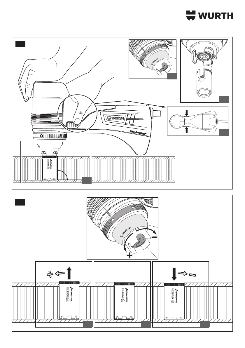
Der WoodWelding® Prozess (Abb.II)
WARNUNG !
Verbrennungsgefahr
¾Verhindern Sie einen direkten Kontakt
der Sonotrode mit der Haut.
VORSICHT !
Gesundheitsgefährdung durch Lärm
¾Geeigneten Gehörschutz tragen!
Achtung !
Vergleichen Sie vor Inbetriebnahme, ob die auf
dem Typenschild angegebene Netzspannung und
Netzfrequenz mit den Daten Ihres Stromnetzes
übereinstimmen.
Hinweis
Achten Sie auf die Beschaenheit der
Arbeitsäche. Diese sollte eben, glatt
und hart sein, damit ein Widerstand zum
Druckaufbau während der Herstellung
einer WoodWelding®Verbindung garan-
tiert wird.
Hinweis
Die vollächige, zentrische Auage der
Sonotrode auf dem Kaltschmelzdübel
(Abb. II/C) ist unbedingt erforderlich.
▸Netzstecker einstecken.
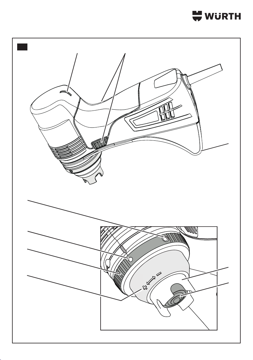
▸Sonotrode [5] vollächig auf den Kaltschmelz-
dübel aufsetzen (Abb. II/B).
▸WoodWelding®-Kaltschmelzgerät durch Auage
auf der Platte ausrichten.
▸Sitz der Sonotrode [5] prüfen (Abb. II/C).
▸Hände entsprechend der Abbildung auf dem
Gerät platzieren.
▸Mittels der oben auiegenden Hand leichten
Druck zur Führung und Stabilisierung auf das
Gerät ausüben, diese Haltung bis zum automati-
schen Abschalten des Gerätes beibehalten.
▸Ein-/Austaster [2] auf beiden Seiten betätigen
(Abb. II/D) und Druck bis zum automatischen
Abschalten beibehalten.
3Status-LED leuchtet auf.
3Status-LED erlischt nach Beendigung des
WoodWelding®Prozesses.
Offset Feineinstellung(Abb.III)
Die Tiefenlage des Kaltschmelzdübels kann bei
Bedarf nachjustiert werden.
Im Auslieferzustand ist das Kaltschmelzgerät für ein
bündiges Arbeitsergebnis eingestellt; d.h. Oberkante
des Kaltschmelzdübels schließt bündig mit der Platte
ab (Abb. III/B). Eine Anpassung kann ergebnisorien-
tiert vorgenommen werden.
Die Stellung des Auswahlrings [7] ist für diese
Einstellung unerheblich.
Kaltschmelzdübel vertieft (Abb. III/C)
▸Schutzabdeckung [4] in Richtung "Minus"
drehen.
3Kaltschmelzdübeloberkante sitzt vertieft.
Kaltschmelzdübel überstehend (Abb. III/A)
▸Schutzabdeckung [4] in Richtung "Plus" drehen.
3Kaltschmelzdübeloberkante sitzt erhöht.
▸Prüfen des Resultats an einem Probestück.
▸Vorgang gegebenenfalls wiederholen.
Wartung und Reinigung
WARNUNG !
Gefahr durch elektrischen Strom.
¾Wartungs- und Reinigungsarbeiten
des Gerätes nur bei gezogenem
Netzstecker.
VORSICHT !
Gefahr von Verletzungen oder
Sachschäden durch unsachgemäße
Tätigkeiten.
¾Gerät nicht öffnen.
¾Das Gerät darf nur vom Würth
masterService geöffnet werden.
¾Bei allen Pege- und
Wartungsarbeiten die
geltenden Sicherheits- und
Unfallverhütungsvorschriften
beachten.
▸WoodWelding®-Kaltschmelzgerät, Stromkabel,
Stecker und Schalter mit einem trockenen, nicht
kratzenden Tuch reinigen.
▸Schwer zu entfernende Verschmutzungen mit
einem nicht üchtigen Reinigungsmittel entfernen.
▸Netzstecker und Kabel regelmäßig auf Beschädi-
gungen prüfen.

9
Zubehör und Ersatzteile
Sollte das WoodWelding®-Kaltschmelzgerät trotz
sorgfältiger Herstell- und Prüfverfahren einmal ausfal-
len, ist die Reparatur von einem Würth masterService
ausführen zu lassen.
In Deutschland erreichen Sie den Würth masterSer-
vice kostenlos unter Tel. 0800-WMASTER
(0800-9 62 78 37). Bei allen Rückfragen und
Ersatzteilbestellungen bitte unbedingt die Artikelnum-
mer laut Typenschild des Gerätes angeben.
Die aktuelle Ersatzteilliste dieses Gerätes kann im
Internet unter „http://www.wuerth.com/partsma-
nager“ aufgerufen oder von der nächstgelegenen
Würth Niederlassung angefordert werden.
Gewährleistung
Für dieses Würth Gerät bieten wir eine Gewährleis-
tung von 2 Jahren ab Kaufdatum (Nachweis durch
Rechnung oder Lieferschein). Entstandene Schäden
werden durch Ersatzlieferung oder Reparatur besei-
tigt. Schäden, die auf unsachgemäße Behandlung
zurückzuführen sind, sind von der Gewährleistung
ausgeschlossen. Beanstandungen können nur aner-
kannt werden, wenn das Gerät unzerlegt einer Würth
Niederlassung, Ihrem Würth Außendienstmitarbeiter
oder einer Würth autorisierten Kundendienststelle
übergeben wird. Technische Änderungen vorbehalten.
Für Druckfehler übernehmen wir keine Haftung.
Entsorgung
Werfen Sie dieses Gerät nicht in den
Hausmüll! Gemäß Europäischer
Richtlinie 2012/19/EU über Elektro-
und Elektronik-Altgeräte und Umsetzung
in nationales Recht, müssen verbrauchte
Elektrowerkzeuge getrennt gesammelt und einer
umweltgerechten Wiederverwertung zugeführt
werden. Stellen Sie sicher, dass Sie Ihr gebrauchtes
Gerät bei Ihrem Händler zurückgeben oder holen Sie
Informationen über ein lokales, autorisiertes Sammel-
und Entsorgungssystem ein. Ein Ignorieren dieser
EU-Direktive kann zu potentiellen Auswirkungen auf
die Umwelt und Ihre Gesundheit führen!
EG-Konformitätserklärung
Wir erklären in alleiniger Verantwortung, dass dieses
Produkt mit den folgenden Normen oder normativen
Dokumenten übereinstimmt:
Normen
• IEC 61000-4-2
• IEC 61000-4-4
• IEC 61000-4-5
• IEC 61000-4-6
• IEC 61000-4-8
• IEC 61000-4-9
• IEC 61000-4-11
• IEC 61000-6-1
• IEC 61000-6-3
• IEC 60745-1
gemäß den Bestimmungen der Richtlinien:
EG-Richtlinie
• 2006/42/EG
• 2004/108/EG
• 2011/65/EU
Technische Unterlagen bei:
Adolf Würth GmbH & Co. KG,
Reinhold-Würth-Straße 12 – 17,
74653 Künzelsau, Germany
M. Strobel Dr.-Ing. S. Beichter
Leiter
Produktmanagement
Prokurist
Leiter Qualität
Künzelsau: 20.10.2015

10
For Your Safety
GB
Please read and comply with
these operating instructions prior
to initial operation of your
device. Keep these operating
instructions for later use or for a
subsequent owner.
▸Prior to rst use always read the safety instruc-
tions!
▸Failure to observe the operating instructions and
the safety instructions could result in damage to
the appliance and danger for the operator and
other persons.
Unauthorised modifications and con-
versions are not permitted
Modication of the device or manufacturing of
additional devices is not permitted. Such modica-
tions can result in personal injury or malfunctions.
▸Only appointed and trained personnel may
carry out repairs to the device. For such
purposes, always use original spare parts from
Adolf Würth GmbH & Co. KG. This will ensure
the continuing safe operation of the device.
Signs and symbols in these instruc-
tions
The signs and symbols in these instructions should
help you to use the instructions and the tool quickly
and safely.
Note
Provides information on the most eec-
tive or most practical use of the device
and these instructions.
▸Handling steps
The dened sequence of handling steps facili-
tates correct and safe use of the device.
3Result
This is where the result of a handling step
sequence is described.
[1] Item number
Item numbers of the gures are identied in the text
with square brackets.
Warning instruction hazard levels
The following hazard levels are used in these oper-
ating instructions to indicate potentially hazardous
situations and important safety rules:
DANGER!
The hazardous situation is about to
occur and will lead to severe injuries
or even death if the measures are not
observed. Observe the measure without
fail.
WARNING !
The hazardous situation could occur
and will lead to severe injuries and even
death if the measures are not observed.
Work with extreme care.
CAUTION!
The hazardous situation could occur
and will lead to slight or minor injuries if
the measures are not observed.
Attention!
A possibly harmful situation could occur and will
lead to property damage if not avoided.
Format of safety instructions
DANGER!
Type and source of the danger!
ÂConsequences of non-observance
¾Danger prevention measure

11
Safety Instructions
Self and personnel protection
▸Persons less than 18 years old must not use the
device. Excepted from this are young persons of
16 and over who are working under supervision
within the scope of their vocational training.
▸Always remain alert and take the utmost care
when working.
▸Do not use the tool if you are tired or under the
inuence of drugs, alcohol or medicines.
▸Do not work with the tool without having been
instructed in its use.
▸Ensure that you can always maintain a safe
standing position and maintain your balance at
all times.
▸Never point the tool towards any part of
your body, towards yourself or towards other
persons.
Safety in the workplace
▸Keep the tool out of the reach of children and
never leave it unattended. When not in use,
keep the tool in a safe place out of the reach of
unauthorised persons.
Electrical safety
▸The tool must not be operated and/or stored in
a wet or damp environment. Do not expose the
device to rain.
ÂIf water penetrates into the electrical device, the
risk of an electric shock is increased.
▸If the device power cord is damaged, it must
be replaced by the manufacturer, its customer
service or a similarly qualied person to prevent
hazards.
General safety instructions
▸Always visually check the device for damage
before initial use and after transport. Ensure any
damage is repaired by trained service personnel
prior to initial use.
▸Route the power supply cabling to ensure it does
not cause a risk of tripping.
▸If necessary wear suitable ear protectors.
▸Use only genuine Würth accessories
and spare parts.
Intended use
The WoodWelding® cold melting device KSG-E is
intended for the connection of special Würth cold
melting dowels to lightweight building boards and
chipboard. The joint is made without glue.
The WoodWelding®cold melting device
KSG-E is not suitable for continuous
operation.
Periodic duty: 2 min. use / 5 min. break
Use only original Würth accessories.
Any other use or use outside this scope is considered
improper use.
The user is solely responsible for damage
resulting from improper use.
Device elements (Fig. I)
Overview
1 Status LED
2 On/o push-button switch
3 Support
4 Protective cover
5 Sonotrode
6 Labelling ne adjustment (oset)
7 Selection ring cold melting dowel type
8 Diameter setting for cold melting dowel screws
9 Diameter setting for cold melting dowel eccentric

12
Technical Data
Art. 0702 9061
Mains voltage: 220 - 240 V, 50 Hz
Input current: max. 2.5 A
Power consumption: max. 500 W
Working frequency approx. 20500 Hz
Weight: 1.7 kg
Dimensions (L x W x H): 250 x 120 x 160 mm
Noise /vibration information
Noise emission values
These values enable the estimating of the noise
emissions of the power tool and comparison with
various power tools. Dependent on the conditions
of use, state of the power tool or attachments, the
actual loading may be greater or smaller. When
estimating also take into consideration work breaks
and phases with lower loading. Specify protective or
organisational measures for the user based on the
appropriately adjusted estimation values.
Noise level according to ISO 15744:2002
Sound pressure level LWA 97 dB(A)
Sound power level LpA 86 dB(A)
Measurement uncertainty 3 dB
Vibration level according to ISO 28927-
2:2009
Vibration emissions < 2.5 m/s2
Measurement uncertainty 1.5 m/s2
The specied vibration emission values:
• Were measured using a standardised test method
and can be used to compare one electric tool
with another.
• Can be used for a rough assessment of the
exposure.
WARNING !
The noise level may exceed 80 dB(A)
during work.
ÂRisk of severe injuries and acoustic
trauma.
¾Wear ear protectors!
Operation (Fig. I/II)
Attention!
Condensation may form if the device is stored or
transported at temperatures below 5°C and then
used at higher temperatures.
ÂCondensation may damage the device or impair
work results.
¾Allow about 30 minutes for acclimatisation.
Cold melting dowel selection
(Fig.II/A)
The cold melting dowels are available in two dier-
ent versions.
To create the WoodWelding®joint, the appropriate
version must be set:
Symbol No. Cold melting dowel
[8] Cold melting dowel screw:
small diameter
[9] Cold melting dowel eccen-
tric:
large diameter
▸Turn the cold melting dowel type selection
ring [7] to the desired position.
Positioning a cold melting dowel
(Fig. II/B)
Note
The perpendicular alignment of the cold
melting dowel in the hole and the full-sur-
face, centred support on the bottom
protective layer are absolutely necessary.
▸Create the hole for the cold melting dowel (see
the separate operating instructions for the cold
melting dowel/drill).
▸Clean the hole (remove drilling chips and ll
material residues).
Note
Incorrect cleaning reduces the joint
quality.
▸Insert the cold melting dowel perpendicularly in
the hole.
▸Check for the full-surface support of the cold
melting dowel on the bottom surface layer by
applying rm pressure.

13
The WoodWelding® process (Fig.II)
WARNING !
Risk of burns
¾Do not allow the Sonotrode to come
into direct contact with the skin.
CAUTION!
Health risk due to noise
¾Wear suitable ear protectors!
Attention!
Before initial use, check that the specications of
your mains power supply correspond to the mains
voltage and mains frequency indicated on the
name plate.
Note
Note the condition of the working sur-
face. It should be smooth, at and hard,
so that resistance to the pressure built
up during creation of a WoodWelding®
joint is ensured.
Note
The full surface, centred support of the
Sonotrode on the cold melting dowel
(Fig. II/C) is essential.
▸Plug in the mains plug.
▸Position the Sonotrode [5] so that its full surface
is on the cold melting dowel (Fig. II/B).
▸Align the WoodWelding® cold melting device on
the board using the support.
▸Check the seating of the Sonotrode [5]
(Fig. II/C).
▸Position the hands on the device as shown in the
gure.
▸With the upper hand apply a slight pressure to
guide and stabilise the device, maintain this hold
until the device switches o automatically.
▸Press the on/o buttons [2] on both sides (Fig.
II/D) and maintain the pressure until the device
switches o automatically.
3The status LED illuminates.
3The status LED goes out once the
WoodWelding® process is completed.
Offset fine adjustment (Fig.III)
If necessary, the depth of the cold melting dowel can
be readjusted.
As supplied, the cold melting device is set for a ush
working result; i.e. the top edge of the cold melting
dowel terminates so that it is ush with the board
(Fig. III/B). An adjustment can be made based on
results.
The position of the selection ring [7] is not important
for this adjustment.
Recessed cold melting dowel (Fig. III/C)
▸Turn the protective cover [4] in the “Minus”
direction.
3The cold melting dowel top edge is recessed.
Protruding cold melting dowel (Fig. III/A)
▸Turn the protective cover [4] in the “Plus” direc-
tion.
3The cold melting dowel top edge is proud.
▸Check the results on a test piece.
▸Repeat the process as necessary.
Maintenance and cleaning
WARNING !
Danger of electric current.
¾Carry out maintenance and cleaning
work on the device only when the
mains plug has been removed.
CAUTION!
Risk of injuries or property damage due
to improper actions.
¾Do not open the device.
¾The device must only be opened by
Würth masterService.
¾Observe the relevant safety and
accident prevention regulations
during all maintenance and servicing
work.
▸Clean the WoodWelding® cold melting device,
power cable, plug and switch with a dry,
non-abrasive cloth.
▸Remove soiling that is dicult to remove using a
non-volatile cleansing agent.
▸Inspect the mains cable and plug for damage at
regular intervals.

14
Accessories and spare parts
If. in spite of careful manufacturing and testing pro-
cesses, the WoodWelding® device becomes faulty, a
repair by Würth masterService should be arranged.
With any enquiries or spare parts orders, always
quote the article number as given on the name plate.
The latest spare parts list for the device is available
online at http://www.wuerth.com/partsmanager.
Alternatively, contact your local Würth agency for a
hardcopy.
Warranty
We provide a 2 year warranty for this Würth device
from the date of purchase (proof of purchase
through invoice or delivery note). Damage that has
occurred will be corrected either by replacement or
by repair. Damage caused by improper handling is
not covered by the warranty. Claims under warranty
can only be accepted if the device is returned fully
assembled to a Würth agency, your Würth sales rep-
resentative or an authorised Würth customer service
workshop. We reserve the right to make technical
changes. We accept no liability for printing errors.
Disposal
Do not dispose of this device in house-
hold waste. According to European
Directive 2012/19/EU on waste
electrical and electronic equipment and
its implementation in national law,
broken and unserviceable electric tools must be
collected separately and submitted to an environ-
mentally sound recycling facility. Ensure that your
used device is returned to your dealer or obtain
information about a local authorised collection and
disposal system. Ignoring this EU directive can have
potential eects on the environment and your health!
EC Declaration of Conformity
We herewith declare that this product conforms to
the following standards and directives:
Standards
• IEC 61000-4-2
• IEC 61000-4-4
• IEC 61000-4-5
• IEC 61000-4-6
• IEC 61000-4-8
• IEC 61000-4-9
• IEC 61000-4-11
• IEC 61000-6-1
• IEC 61000-6-3
• EN 60745-1
in accordance with the regulations stipulated in the
directives:
EC Directive
• 2006/42/EC
• 2004/108/EC
• 2011/65/EU
Technical documentation with:
Adolf Würth GmbH & Co. KG,
Reinhold-Würth-Straße 12 – 17,
74653 Künzelsau, Germany
M. Strobel Dr.-Ing. S. Beichter
Head of
Product Management Head of Quality,
Authorized Signatory
Künzelsau: 20.10.2015

15
Informazioni per la sicurezza
IT
Prima di utilizzare l'apparecchio
per la prima volta, leggere e
seguire queste istruzioni per
l'uso. Conservare le presenti istruzioni
per l'uso per consultarle in un secondo
tempo o per consegnarle a successivi
proprietari.
▸Prima di mettere in funzione l'apparecchio per la
prima volta leggere attentamente le Avvertenze
di sicurezza.
▸La mancata osservanza delle istruzioni d'uso
e delle norme di sicurezza può causare danni
all'apparecchio e presentare pericoli per l'utente
e le altre persone.
Divieto di modifiche e conversioni
arbitrarie
Vietato apportare modiche all'apparecchio o
installare dispositivi aggiuntivi. Tali modiche pos-
sono portare a danni alle persone e ad anomalie
di funzionamento.
▸I lavori di riparazione sull'apparecchio possono
essere eseguiti solo da personale incaricato e
con adeguata formazione. Per questi lavori uti-
lizzare sempre i pezzi di ricambio originali della
Adolf Würth GmbH & Co. KG. In questo modo
è garantita la sicurezza dell'apparecchio.
Segnali e simboli contenuti nelle istru-
zioni per l'uso
I segnali e i simboli contenuti nelle presenti istru-
zioni per l'uso dovrebbero contribuire all'utilizzo
rapido e corretto delle istruzioni e della macchina.
Nota
Fornisce suggerimenti sull'utilizzo più
ecace e pratico dell'apparecchio e
delle istruzioni.
▸Fasi operative
La sequenza denita delle fasi operative per-
mette un utilizzo corretto e sicuro.
3Risultato
Qui viene descritto il risultato di una sequenza
di fasi operative.
[1] Numero di posizione
I numeri di posizione delle gure sono riportati nel
testo all’interno di parentesi quadre.
Livelli di pericolo delle avvertenze
In queste istruzioni per l'uso vengono utilizzati i
seguenti livelli di pericolo per segnalare potenziali
situazioni di pericolo e disposizioni di sicurezza
importanti:
PERICOLO!
La situazione pericolosa è imminente
e, in caso di mancata osservanza
delle disposizioni, causa lesioni gravi
o mortali. Osservare assolutamente le
disposizioni.
AVVERTENZA!
È possibile che si verichi una situazione
pericolosa che, in caso di mancata
osservanza delle disposizioni, può
causare lesioni gravi o mortali. Lavorare
con la massima prudenza.
ATTENZIONE!
È possibile che si verichi una situazione
pericolosa che, in caso di mancata
osservanza delle disposizioni, può
causare lesioni lievi o limitate.
Avviso!
È possibile che si verichi una situazione
potenzialmente pericolosa che, se non evitata, può
causare danni materiali.
Organizzazione delle avvertenze di
sicurezza
PERICOLO!
Tipo e fonte di pericolo.
ÂConseguenze in caso di mancata
osservanza
¾Disposizione per rafforzamento della
sicurezza

16
Avvertenze di sicurezza
Protezione personale e delle persone
▸Le persone di età inferiore ai 18 anni non
devono lavorare con il dispositivo. Fanno ecce-
zione i ragazzi di età superiore ai 16 anni che
si trovano in un rapporto lavorativo di forma-
zione e lavorano sotto supervisione.
▸Prestare la massima attenzione e lavorare con
buon senso.
▸Non utilizzare il dispositivo se si è stanchi o
sotto l'eetto di droghe, alcool o altri farmaci.
▸Non lavorare mai con il dispositivo se non si
è ricevuta adeguata formazione all'uso dello
stesso.
▸Assicurare una buona stabilità e mantenere
sempre l'equilibrio.
▸Non rivolgere mai il dispositivo verso una parte
del corpo, verso se stessi o altre persone.
Sicurezza nell'area di lavoro
▸Tenere il dispositivo lontano dalla portata dei
bambini e non lasciarlo mai incustodito. Se
non lo si utilizza, conservare il dispositivo in
un luogo al sicuro dall'accesso di persone non
autorizzate.
Sicurezza elettrica
▸L'apparecchio non deve essere utilizzato e/o
conservato in ambienti umidi o bagnati. L'appa-
recchio non deve essere esposto alla pioggia.
ÂQualora penetri acqua nell'apparecchio elettri-
co, ciò aumenta il rischio di scossa elettrica.
▸Se il cavo di alimentazione di questo apparec-
chio è danneggiato, per evitare qualsiasi tipo
di pericolo farlo sostituire dal costruttore / dal
suo servizio clienti o da una persona altrettanto
qualicata.
Avvertenze di sicurezza generali
▸Prima della messa in funzione e dopo il tra-
sporto eseguire sempre un controllo visivo del
dispositivo per escludere danni. Eventuali danni
prima della messa in servizio vengono riparati
dal personale di assistenza sottoposto ad ade-
guata formazione.
▸Prestare attenzione al cavo d’alimentazione: vi è
il rischio di inciamparci sopra.
▸Se necessario indossare delle cue insonoriz-
zanti adatte.
▸Utilizzare solo accessori e pezzi di
ricambio originali Würth.
Uso conforme
L’apparecchio per la giunzione a freddo
WoodWelding®KSG-E serve per unire la speciale
giunzione eccentrica Würth con leggere lastre di
materiale da costruzione e pannelli di truciolato. La
giunzione avviene senza bisogno di colla.
L’apparecchio per la giunzione a freddo
WoodWelding®KSG-E non è adatto per il
servizio continuo.
Servizio intermittente: 2 min. in uso / 5 min. pausa
Utilizzare esclusivamente accessori della Würth.
Qualsiasi utilizzo dierente viene considerato non
conforme.
La responsabilità per i danni dovuti a un
utilizzo non conforme alle norme è esclusi-
vamente dell'utente.
Elementi dell'apparecchio (Fig. I)
Panoramica
1 LED di stato
2 Pulsante di accensione/spegnimento
3 Supporto
4 Protezione
5 Elettrodo ultrasonico
6 Contrassegni per la microregolazione (oset)
7 Ghiera selettrice per la selezione del tipo di
giunzione eccentrica
8 Impostazione del diametro delle viti per le giun-
zioni eccentriche
9 Impostazione del diametro degli eccentrici per
le giunzioni eccentriche

17
Dati tecnici
Art. 0702 9061
Tensione di rete: 220 - 240 V, 50 Hz
Corrente di ingresso: max. 2,5 A
Potenza assorbita: max. 500 W
Frequenza di lavoro: ca. 20500 Hz
Peso: 1,7 kg
Dimensioni (L x L x H): 250 x 120 x 160 mm
Informazioni su rumore/vibrazione
Valori di emissione
Questi valori permettono di stimare le emissioni
dell'utensile elettrico e il confronto di diversi utensili
elettrici. A seconda delle condizioni d'utilizzo, dello
stato dell'utensile elettrico o degli utensili impiegati,
la sollecitazione eettiva può risultare maggiore o
minore. Per la stima delle pause di lavoro tenere
conto delle fasi a sollecitazione ridotta. Sulla base di
adeguati valori stimati adottare misure di sicurezza
per l'utente, p. es. misure organizzative.
Livello sonoro a norma ISO 15744:2002
Livello di pressione acustica LWA 97 dB(A)
Livello di potenza sonora LpA 86 dB(A)
Incertezza di misurazione 3 dB
Livello di vibrazioni a norma ISO 28927-
2:2009
Valore di emissione dell'oscil-
lazione < 2,5 m/s2
Incertezza di misurazione 1,5 m/s2
I valori indicati relativi alle emissioni di vibrazioni:
• sono stati misurati secondo il procedimento di
prova normato e possono essere utilizzati ai ni
della comparazione con un altro apparecchio
elettrico.
• Possono essere utilizzati per una stima prelimina-
re dell'esposizione.
AVVERTENZA!
Durante il lavoro il livello acustico può
superare gli 80dB(A).
ÂPericolo di lesioni gravi e traumi
acustici.
¾Indossare protezioni per l'udito.
Comandi (g. I/II)
Avviso!
In caso di immagazzinaggio/trasporto a
temperature inferiori a 5 °C e successivo impiego
a temperature maggiori, si avrà la formazione di
acqua di condensa.
ÂL’acqua di condensa può danneggiare l’appa-
recchio e/o compromettere il risultato di lavoro.
¾Attendere ca. 30 min. per consentire
l’acclimatazione.
Selezione della giunzione eccentrica
(fig.II/A)
Le giunzioni eccentriche sono disponibili in due
diverse versioni.
Per la giunzione WoodWelding®, impostare la
versione corretta:
Simbolo N. Giunzione eccentrica
[8] Vite per giunzione eccen-
trica:
diametro piccolo
[9] Eccentrico per giunzione
eccentrica:
diametro grande
▸Ruotare la ghiera selettrice per la selezione del
tipo di giunzione eccentrica [7] nella posizione
desiderata.
Posizionare la giunzione eccentrica
(fig. II/B)
Nota
È assolutamente indispensabile assicura-
re un allineamento perpendicolare della
giunzione eccentrica nel foro e garantire
un appoggio centrato dell’intera super-
cie sullo strato di copertura inferiore.
▸Realizzare il foro per la giunzione eccentrica
(vedi il manuale separato della giunzione eccen-
trica/della punta da trapano).
▸Pulire il foro (rimuovere i trucioli di foratura e i
residui del materiale di riempimento).
Nota
Una pulizia non eseguita correttamente
riduce la qualità della giunzione.
▸Inserire la giunzione eccentrica perpendicolare
nel foro.

18
▸Premere con fermezza in modo da controllare
che l’intera supercie di appoggio della giun-
zione eccentrica poggi sullo strato di copertura
inferiore.
Il processo WoodWelding® (fig.II)
AVVERTENZA!
Pericolo di ustioni
¾Evitare un contatto diretto
dell’elettrodo ultrasonico con la pelle.
ATTENZIONE!
Pericolo per la salute dovuto al rumore
¾Indossare cue insonorizzanti
idonee.
Avviso!
Prima della messa in funzione, vericare che la
tensione di rete e la frequenza di rete indicate sulla
targhetta corrispondano ai dati della rete in uso.
Nota
Considerare le caratteristiche della
supercie di lavoro. Deve essere piana,
liscia e dura, in modo da garantire una
resistenza alla pressione che si forma du-
rante la realizzazione di una giunzione
WoodWelding®.
Nota
È assolutamente indispensabile che l’elet-
trodo ultrasonico poggi in modo centrato
con l’intera supercie sulla giunzione
eccentrica (g. II/C).
▸Inserire la spina di alimentazione.
▸Posizionare l’elettrodo ultrasonico [5] in modo
che l’intera supercie poggi sulla giunzione
eccentrica (g. II/B).
▸Attraverso il supporto allineare l’apparecchio
per la giunzione a freddo WoodWelding®sulla
lastra.
▸Controllare la sede dell’elettrodo ultrasonico [5]
(g. II/C).
▸Posizionare le mani sull’apparecchio come
mostrato nella gura.
▸Con la mano superiore applicare una leggera
pressione in modo da guidare e stabilizzare
l’apparecchio e mantenere questa posizione no
al disinserimento automatico dell’apparecchio.
▸Premere il pulsante di accensione/spegni-
mento [2] su entrambi i lati (g. II/D) e mante-
nerlo premuto no al disinserimento automatico.
3Il LED di stato si accende.
3Il LED di stato si spegne al termine del processo
WoodWelding®.
Microregolazione dell’offset (fig.III)
Se necessario, la profondità della giunzione eccen-
trica può essere regolata.
Alla consegna, l’apparecchio per la giunzione a
freddo è impostato in modo da garantire un risultato
di lavoro perfettamente a lo; vale a dire che il
bordo superiore della giunzione eccentrica si trova
a lo con la lastra (g. III/B). È possibile eettuare
un adattamento di questa regolazione in funzione
del risultato.
Per questa regolazione la posizione della ghiera
selettrice [7] è irrilevante.
Giunzione eccentrica infossata (g. III/C)
▸Ruotare la protezione [4] in direzione “meno”.
3Il bordo superiore della giunzione eccentrica
risulta infossato.
Giunzione eccentrica sporgente (g. III/A)
▸Ruotare la protezione [4] in direzione “più”.
3Il bordo superiore della giunzione eccentrica
risulta sporgente.
▸Controllare il risultato su un pezzo campione.
▸Se necessario ripetere l’operazione.
Manutenzione e pulizia
AVVERTENZA!
Pericolo per corrente elettrica.
¾Eseguire i lavori di manutenzione e
pulizia dell'apparecchio solo dopo
aver staccato la spina.
ATTENZIONE!
Pericolo di lesioni o danni materiali a
causa di operazioni non corrette.
¾Non aprire l'apparecchio.
¾L'apparecchio può essere aperto
esclusivamente dal Würth
masterService.
¾Per tutte le operazioni di cura e
manutenzione, attenersi alle norme
di sicurezza e prevenzione degli
infortuni in vigore.

19
▸Pulire l’apparecchio per la giunzione a freddo
WoodWelding®, il cavo elettrico, la spina e
l'interruttore con un panno asciutto che non gra.
▸Rimuovere lo sporco ostinato con un detergente
non volatile.
▸Controllare regolarmente se la spina e il cavo
sono danneggiati.
Accessori e pezzi di ricambio
Se nonostante l'accurata procedura di produzione
e controllo l’apparecchio per la giunzione a freddo
WoodWelding® dovesse guastarsi, farlo riparare
presso il Würth masterService.
Per qualsiasi domanda od ordinazione di ricambi,
indicare sempre la matricola dell'articolo indicata
sulla targhetta identicativa dell'apparecchio.
Il listino dei pezzi di ricambio aggiornato per questo
apparecchio è disponibile su Internet all’indirizzo
"http://www.wuerth.com/partsmanager" oppure
può essere richiesto alla sede Würth più vicina.
Garanzia
Per il presente apparecchio Würth il costruttore
fornisce una garanzia di 2 anni dal momento
dell'acquisto (da dimostrare con fattura o bolla
d'accompagnamento). In caso di danni, il prodotto
verrà sostituito o riparato. I danni riconducibili ad un
uso improprio dell'apparecchio sono esclusi dalla
garanzia. Le richieste potranno essere riconosciute
soltanto se l'apparecchio verrà consegnato integro
ad una liale Würth, ad un rappresentante Würth o
al servizio di assistenza clienti autorizzato da Würth.
Con riserva di modiche tecniche. Il costruttore non
si assume alcuna responsabilità per eventuali refusi.
Smaltimento
Non gettare questo dispositivo tra i
riuti domestici. Conformemente alla
direttiva europea 2012/19/UE sugli
apparecchi elettrici ed elettronici vecchi
e il relativo recepimento nel diritto
nazionale, gli utensili elettrici usati devono essere
oggetto di una raccolta dierenziata ed essere
avviati ad un riciclaggio condotto nel rispetto
dell'ambiente. Restituire il dispositivo usato al proprio
rivenditore o informarsi riguardo ad un centro locale
di raccolta e smaltimento autorizzato. Il mancato
rispetto di questa direttiva UE può avere eetti
signicativi sull'ambiente e la salute.
Dichiarazione di conformità CE
Dichiariamo, sotto nostra esclusiva responsabilità,
che questo prodotto è conforme alle seguenti norme
o prescrizioni normative:
Norme
• IEC 61000-4-2
• IEC 61000-4-4
• IEC 61000-4-5
• IEC 61000-4-6
• IEC 61000-4-8
• IEC 61000-4-9
• IEC 61000-4-11
• IEC 61000-6-1
• IEC 61000-6-3
• IEC 60745-1
secondo le disposizioni delle direttive:
Direttiva CE
• 2006/42/CE
• 2004/108/CE
• 2011/65/UE
Documentazione tecnica presso:
Adolf Würth GmbH & Co. KG,
Reinhold-Würth-Straße 12 – 17,
74653 Künzelsau, Germany
M. Strobel Dr.-Ing. S. Beichter
Responsabile
gestione prodotto Procuratore
Responsabile qualità
Künzelsau: 20.10.2015

20
Pour votre sécurité
FR
Veuillez lire attentivement le
présent mode d'emploi et le
respecter à la lettre avant
d'utiliser l'appareil pour la
première fois. Conservez ce mode
d’emploi pour un usage ultérieur ou
pour les futurs propriétaires.
▸Avant la première mise en service, lire impérati-
vement les consignes de sécurité !
▸En cas de non-respect du mode d’emploi et des
consignes de sécurité, l'appareil peut subir des
dommages et l'opérateur et d'autres personnes
s'exposent à des risques.
Interdiction de procéder à des modifi-
cations et transformations arbitraires
Il est interdit de procéder à des modications
sur l’appareil ou de fabriquer tout équipement
additionnel. De telles modications risquent
de provoquer des dommages corporels et des
dysfonctionnements.
▸Les réparations eectuées sur l’appareil ne
doivent être réalisées que par des personnes
mandatées et formées. Pour ceci, il faut toujours
utiliser les pièces détachées de la société Adolf
Würth GmbH & Co. KG. Ceci permet de ga-
rantir et de préserver la sécurité de l'appareil.
Signes et symboles de la présente
notice
Les signes et symboles gurant dans le présent
mode d'emploi sont censés permettre une utilisation
rapide et sûre de la machine et du mode d'emploi.
Remarque
Les informations vous informent sur
l’utilisation la plus eective et la plus
praticable de l’appareil et de la pré-
sente notice.
▸Démarches de manipulation
L’ordre déni des démarches de manipulation
vous facilite la correction et la sécurité d’utilisa-
tion.
3Résultat
Vous trouverez ici la description du résultat d’un
ordre de démarches de manipulation.
[1] Numéro de position
Les numéros de position des illustrations sont carac-
térisés dans le texte par des crochets.
Niveaux de danger des
avertissements
Le présent mode d’emploi utilise les niveaux de
danger suivants an d’indiquer les situations poten-
tiellement dangereuses et les directives de sécurité
importantes :
DANGER!
La situation dangereuse est imminente,
elle entraîne des blessures graves,
voire mortelles si les mesures ne sont
pas observées. Veuillez observer
absolument la mesure.
AVERTISSEMENT!
La situation dangereuse peut se
produire et elle entraîne des blessures
graves, voire mortelles si les mesures ne
sont pas observées. Veuillez travailler
avec le plus grand soin.
PRUDENCE!
La situation dangereuse peut se
produire et elle entraîne des blessures
légères ou minimes si les mesures ne
sont pas observées.
Attention!
Une situation potentiellement préjudiciable peut se
produire et entraîner des dommages matériels, si
elle n’est pas évitée.
Structure des consignes de sécurité
DANGER!
Type et source du danger!
ÂConséquences en cas de non-respect
¾Mesure pour parer le risque
This manual suits for next models
1
Table of contents
Languages:
Other wurth Tools manuals
Popular Tools manuals by other brands

Chicago Electric
Chicago Electric 63409 Owner's manual and safety instructions

DICSA
DICSA CBOXSMART instruction manual

BGS technic
BGS technic 9992 instruction manual

Clarke
Clarke CONTRACTOR CSJ100 Operation & maintenance instructions

Samoa
Samoa 168 600 Parts and technical service guide

Porter-Cable
Porter-Cable 4212 instruction manual