manuals.online logo
Brands
  1. Home
  2. •
  3. Brands
  4. •
  5. Wyrestorm
  6. •
  7. Switch
  8. •
  9. Wyrestorm SW-0501-HDBT User manual

Wyrestorm SW-0501-HDBT User manual

IMPORTANT! Installation Requirements!
• Visit the product page to download the latest rmware, document versions,
and the WyreStorm Maintenance Suite conguration tools.
• Install the latest rmware to ensure that all features described in this
document are available.
• WyerStorm recommends the use of static IP addresses to ensure that the
devices IP address will not change after power is restored or if network
components are changed. See Switcher First Time Conguration for details
on changing the IP Address.
• In order to use ScreenLink software is required on the presentation PC. See
ScreenLink Presentation Software for details on using ScreenLink
• When using ScreenLink, the switcher is required to be on the same Local
Area Network (LAN) as the presentation PCs.
In the Box
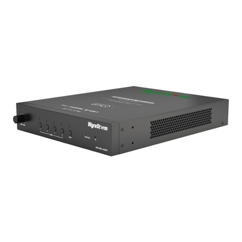
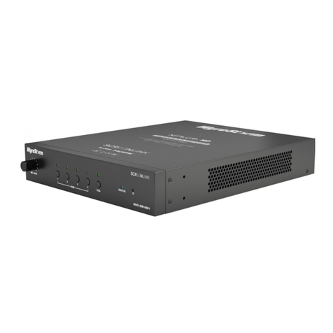
1x SW-0501-HDBT Presentation Switcher
1x 100~240V AC 50/60Hz Power Cord with US Plug
1x 11-pin Phoenix Connector
2x 4-pin Phoenix Connector
3x 3-pin Phoenix Connector
1x Table Mounting Bracket Kit
1 x Quickstart guide (This Document)
Additional Information
Visit the product page on wyrestorm.com to download additional
documentation, rmware, software, and control drivers.
• SW-0501-HDBT Latest Firmware
• SceenLink Presentation Software for PC or Mac
• Control System API
• Control Drivers for Various Control Systems
Copyright © 2017 WyreStorm Technologies | wyrestorm.com
SW-0501-HDBT Quickstart Guide | 170327
North America: 518-289-1294 | EMEA/ROW: 44 (0) 1793 230 343
[email protected]
1 of 4
WyreStorm recommends reading through this document in its entirety to become familiar with the product’s features prior to starting the
installation process.
Basic Wiring Diagram
The following diagram is provided to illustrate a typical basic system containing the SW-0501-HDBT.
KEY
HDMI/DisplayPort
HDBaseT/Ethernet Speaker Level Audio
Analog Video
Analog Audio
Power
Analog Audio
VGA Source
Wireless
Router
VGA Video
Podium PC
with Microphone
HDMI
Speaker Level Audio
IR RS-232
Ethernet
Ethernet
RX-70-4K
5x1 HDMI over HDBaseT Presentation Switcher/Scaler
with Mic Input and CEC control (1080p to 100m/328ft)
SW-0501-HDBT Quickstart Guide
Copyright © 2017 WyreStorm Technologies | wyrestorm.com
SW-0501-HDBT Quickstart Guide | 170327
North America: 518-289-1294 | EMEA/ROW: 44 (0) 1793 230 343
[email protected]
2 of 4
Wiring and Connections
WyreStorm recommends that all wiring for the installation is run and terminated prior to making connections to the switcher. Read through this section in this
entirety before running or terminating the wires to ensure proper operation and to avoid damaging equipment.
IMPORTANT! Wiring Guidelines
• The use of patch panels, wall plates, cable extenders, kinks in cables, and
electrical or environmental interference will have an adverse effect on HDMI
and Ethernet transmission limiting performance. Steps should be taken to
minimize or remove these factors completely during installation for best
results.
• WyreStorm recommends using high quality VGA and HDMI cables such as
WyreStorm Express to ensure the highest content performance available.
• The type of category cable and length used can restrict the available video
resolution. While Cat5e can be used, WyreStorm recommends using Cat6
or higher to ensure the highest content performance available. See Video
Resolutions in the Specications table before determining cable type and
length.
IR Wiring
IR Receiver Connection Guidlines
3rd party IR receivers may require a different voltage, refer to the
documentation provided with the IR receiver before making any connections to
avoid damaging the device.
Wire colors shown are for pin identificaiton only and do not
represent any wiring standard.
Pin 1:
Pin 2:
In Positive (+)
In +5V
Pin 3:
Pin 4:
In/Out GND (Common)
Out Positive (+)
Pin 5: Out +5V
1 2 3 4 5
RS-232 Wiring
Most control systems and computers are DTE where pin 2 is RX, this can vary from device to device. Refer to the documentation for the connected device for
pin functionally to ensure that the correct connections can be made.
RS-232 1 - Control of the SW-0501-HDBT using a 4-pin phoenix connector.
RS-232 2 - Control of local devices using a 4-pin phoenix connector.
RS-232 - Control of devices in a remote location by sending control signals via HDBaseT using a 3-pin phoenix connector.
1 2 3 4
to Control
System
to Control
System
1 2 3 4
to Local
Source
1 2 3
RS-232 1/2 Pinout
Not Available on NHD-SW-0501
Pin 2:
Pin 3:
TX (Transmit)
Pin 1: (Not Used)
RX (Receive)
Pin 4: Ground (GND)
RS-232 (HDBaseT ) Pinout
Pin 2:
Pin 3:
TX (Transmit)
Pin 1:
RX (Receive)
Ground (GND)
Wire colors shown are for pin identificaiton only and do not represent any wiring standard.
to RS-232 1
Switcher
Control
Local Device
Control
Remote Device
Control
to RS-232 2 to RS-232
Audio In / Audio Out Wiring
The switcher contains an Audio In that is used to sync audio with video from
the VGA input and an Audio Out that can be used to distribute the audio
throughout the room by connecting to an audio pre-amplier or powered
speaker. These connections use 3-pin phoenix connectors that are supplied
with the unit.
Pin 1:
Pin 2:
Left Positive (+)
Right Positive (+)
Pin 3: Ground (GND)
Wire colors shown are for pin identificaiton only and do not
represent any wiring standard.
1 2 3
Microphone Wiring
The Mic In uses a 3-pin phoenix connector (supplied).
Pin 1:
Pin 2:
Positive (+)
Negative (-)
Pin 3: Ground (GND)
Wire colors shown are for pin identificaiton only and do not
represent any wiring standard.
1 2 3
Copyright © 2017 WyreStorm Technologies | wyrestorm.com
SW-0501-HDBT Quickstart Guide | 170327
North America: 518-289-1294 | EMEA/ROW: 44 (0) 1793 230 343
[email protected]
3 of 4
Remote I/O Control Device Wiring
The SW-0501-HDBT may be controlled using a contract closure remote I/O device. Connection uses an 11-pin phoenix connector that also provides LED
feedback to the device for all 5 inputs.
Pin 1:
Pin 2:
Pin 3:
Pin 4:
Pin 5:
Pin 6:
Pin 7:
Pin 8:
HDMI 1 Contact In
HDMI 2 Contact In
HDMI 3 Contact In
HDMI 4 Contact In
VGA Contact In
Contact/LED GND
HDMI 1 LED
HDMI 2 LED
Pin 9:
Pin 10:
HDMI 3 LED
HDMI 4 LED
Pin 11: VGA LED
Wire colors shown are for pin identification only and do not represent any wiring standard.
1 2 3 4 5 6 7 8 9 10 11
Setup and Conguration
Switcher First Time Conguration
The SW-0501-HDBT requires a rst time conguration process before connecting to a network. By default version 1 of the switcher running rmware v2.9
or lower is set to an IP address (192.168.1.1) that may interfere with a network connection. The IP address of the switcher must be changed prior to connection
the switcher to a LAN. These steps can be skipped for any switcher that has already been congured to connect to a network and has an IP address other than
192.168.1.1.
1. Congure PC for direct connection to the switcher.
a. Disconnect the Ethernet cable
b. Disable Wireless
c. Connect the LAN port on the switcher directly into the Ethernet port on a PC.
d. Set your PC’s IPv4 address to a static address of 192.168.1.2, subnet mask 255.255.255.0. Gateway can be left blank.
2. Close the IPv4 settings window and conrm settings have taken by viewing the details button.
3. Once saved, open any browser and enter 192.168.1.1 into the address bar.
4. In the open dialog enter the Username and Password.
Default- Username: admin / Password: admin
5. In the open window, navigate to System > Network.
6. Set the following parameters:
Before setting a new IP Address ensure that it is recorded so that the switcher may be accessed once a new IP Address is set.
IP Mode: Static
IP Address: IP Address to set – Should be outside of routers DHCP range
NetMask: Netmask used by the router - Usually 255.255.255.0
Gateway: Gateway used by the router - Usually the routers IP address
7. Click Apply after entering the above information.
8. Reboot the switcher by removing power for 10 seconds and then reapplying it.
9. Disconnect the PC from the switcher, enable wireless and reconnect the Ethernet port to a LAN.
10. Ensure you set you Ethernet IPv4 settings back to DHCP or your previous static address.
11. Connect the switcher to the same LAN as the PC.
ScreenLink Presentation Software
WyreStorm’s ScreenLink is a free rmware update that enables wireless connection to the presentation software. It is a powerful collaboration tool that is
ideally suited for the corporate and educational environment. This feature was not always available on the SW-0501-HDBT v1 and units with rmware v2.8.5.1
or lower require that new rmware is installed in order to take advantage of ScreenLink within an installation.
Refer to the SW-0501-HDBT ScreenLink Installation App Note located on WyreStorm.com for details on installing ScreenLink before proceeding with using
ScreenLink.
Installing ScreenLink on Presentation PC
1. Open a web browser and enter in the NHD-SW-0501s IP address or visit ScreenLink.com to download the software.
2. The download page for ScreenLink will appear. Choose the appropriate installer and complete the installation process.
3. For instruction on how to use ScreenLink view the ScreenLink User Guide available for download at WyreStorm.com.
Warranty Information
This product is covered by a 3 year limited parts and labor warranty. During this period there will be no charge for unit repair,
component replacement or complete product replacement in the event of malfunction. The decision to repair or replace will
be made by the manufacturer. This limited warranty only covers defects in materials or workmanship and excludes normal
wear and tear or cosmetic damage. Visit the product page located at wyrestorm.com for additional information on this
product including important technical information not provided in this document and warranty terms & conditions.
Specications
Copyright © 2017 WyreStorm Technologies | wyrestorm.com
SW-0501-HDBT Quickstart Guide | 170327
North America: 518-289-1294 | EMEA/ROW: 44 (0) 1793 230 343
[email protected]
4 of 4
Power
Power Supply Input: 100~240V AC 50/60Hz
PoH 48V 15.4W
Max. Power Consumption 88.6W
Environmental
Operating Temperature 32°F ~ 113°F (0°C ~ 45°C)
10% ~ 90%, non-condensing
Storage Temperature -4°F ~ 158°F (-20°C ~ +70°C)
10% ~ 90%, non-condensing
Maximum BTU 302.3 BTU/hr
Dimensions and Weight
Rack Units 1U
Height With | Without
Feet 51.3mm/2.02in | 43.5mm/1.72in
Width With | Without
Rack Ears N/A | 220mm/8.67in
Depth With | Without
Handles 297.8mm/11.73in | 280mm/11.03in
Weight 2.3kg/5.07lbs
Regulatory
Safety and Emission CE | FCC | RoHS
Audio and Video
Inputs 4x HDMI 19-pin type A | 1x VGA 15-pin DSUB15 VGA
1x Audio In (VGA Audio) 3-pin Screw Down Phoenix Connector | 1x Audio Out 3-pin Screw Down Phoenix Connector
Outputs 1x HDMI 19-pin type A | 1x HDBaseT 8-pin RJ-45 female
Audio Formats 2ch PCM
Video Resolutions (Max)
HDMI: 1920x1200p @60Hz 12bit (15m/50ft) | 16bit (7m/23ft)
Cat6: 1920x1200p @60Hz 12bit (100m/328ft) | @60Hz 16bit (70m/230ft)
Cat6a/7: 1920x1200p @60Hz 12bit (100m/328ft)
Color Depth 1080p: 16Bit
Maximum Pixel Clock HDMI: 194MHz | HDBaseT: 194MHz
Communication and Control
HDMI HDCP 1.4 compliant | DVI/D supported with adapter (not included)
HDBaseT HDCP 1.4 compliant | EDID | 1-way PoH | Bidirectional IR and Ethernet
Ethernet 1x 8-pin RJ-45 female | Web UI | IP Control | Bidirectional over HDBaseT
IR 5-pin Phoenix (1x IR TX / 1x IR RX) | Bidirectional over HDBaseT
RS-232 Matrix Control | Firmware Updates
3-pin Phoenix | Bidirectional over HDBaseT
Troubleshooting
No or Poor Quality Picture (snow or noisy image)
• Verify that power is being supplied to all devices in the system and that
they are powered on. When using PoH, to power an HDBaseT receiver,
verify that the HDBaseT cable is properly to the 568B terminated standard.
• Verify that all source and HDBaseT connections are not loose and are
functioning properly.
• Verify that the transmitter, receiving device, and display support the output
resolution of the source. Refer to Video Resolutions in the Specications
table for the max distance based on resolution.
No or Intermittent 3rd party Device Control
• Verify that IR and RS-232 cable(s) are properly terminated per the
appropriate wiring section:
o IR: IR Wiring
o RS-232: RS-232 Wiring
• Verify that the IR emitter is located over or near the IR sensor on the device.
Move the emitter closer or further from the sensor as the IR signal can be
too strong in some cases.
• Verify that the IR receiver is in line of sight of the handheld remote.
Troubleshooting Tips:
• WyreStorm recommends using a cable tester or connecting the cable to
other devices to verify functionality.
• Use a flashlight to locate the IR sensor behind any tinted panels on the
device being controlled. It will likely appear as a small round disc.
Other manuals for SW-0501-HDBT

4

Other Wyrestorm Switch manuals

Wyrestorm SW-1102 User manual

Wyrestorm

Wyrestorm SW-1102 User manual

Wyrestorm NHD-400-RX User manual

Wyrestorm

Wyrestorm NHD-400-RX User manual

Wyrestorm MX-0404-POH-KIT User manual

Wyrestorm

Wyrestorm MX-0404-POH-KIT User manual

Wyrestorm EXP-MX0402-010 User manual

Wyrestorm

Wyrestorm EXP-MX0402-010 User manual

Wyrestorm MX0404-HDC User manual

Wyrestorm

Wyrestorm MX0404-HDC User manual

Wyrestorm SW-540-TX-W User manual

Wyrestorm

Wyrestorm SW-540-TX-W User manual

Wyrestorm SW-740-TX User manual

Wyrestorm

Wyrestorm SW-740-TX User manual

Wyrestorm Essentials EXP-SW-0401-H2 User manual

Wyrestorm

Wyrestorm Essentials EXP-SW-0401-H2 User manual

Wyrestorm NHD-SW-0501 User manual

Wyrestorm

Wyrestorm NHD-SW-0501 User manual

Wyrestorm SW-0201-POH User manual

Wyrestorm

Wyrestorm SW-0201-POH User manual

Wyrestorm NHD-SW-0501 User manual

Wyrestorm

Wyrestorm NHD-SW-0501 User manual

Wyrestorm SW-1001-HDBT User manual

Wyrestorm

Wyrestorm SW-1001-HDBT User manual

Wyrestorm EXP-SW-0501 User manual

Wyrestorm

Wyrestorm EXP-SW-0501 User manual

Wyrestorm MX-0404-H2 User manual

Wyrestorm

Wyrestorm MX-0404-H2 User manual

Wyrestorm SW-0201-4K User manual

Wyrestorm

Wyrestorm SW-0201-4K User manual

Wyrestorm EXP-MX0402-010 User manual

Wyrestorm

Wyrestorm EXP-MX0402-010 User manual

Wyrestorm MX-0808-HDBT User manual

Wyrestorm

Wyrestorm MX-0808-HDBT User manual

Wyrestorm SPL1T801 User manual

Wyrestorm

Wyrestorm SPL1T801 User manual

Wyrestorm SW-220-TX-W User manual

Wyrestorm

Wyrestorm SW-220-TX-W User manual

Wyrestorm SW-0401-HDBT User manual

Wyrestorm

Wyrestorm SW-0401-HDBT User manual

Wyrestorm APO-DG1 User manual

Wyrestorm

Wyrestorm APO-DG1 User manual

Wyrestorm EXP-SW-0301 User manual

Wyrestorm

Wyrestorm EXP-SW-0301 User manual

Wyrestorm SW-0402-MV-HDBT User manual

Wyrestorm

Wyrestorm SW-0402-MV-HDBT User manual

Wyrestorm MX-0808-PP-AUD User manual

Wyrestorm

Wyrestorm MX-0808-PP-AUD User manual

Popular Switch manuals by other brands

Crestron CEN-AVF-HUB Do guide

Crestron

Crestron CEN-AVF-HUB Do guide

Edge-Core AS7712-32X Safety and regulatory information

Edge-Core

Edge-Core AS7712-32X Safety and regulatory information

iHome Hi20 Quick setup guide

iHome

iHome Hi20 Quick setup guide

ZyXEL Communications XGS-4728F user guide

ZyXEL Communications

ZyXEL Communications XGS-4728F user guide

Comtrol ROCKET LINX ES7506 user guide

Comtrol

Comtrol ROCKET LINX ES7506 user guide

DITEC COM502ES installation manual

DITEC

DITEC COM502ES installation manual

Extreme Networks Summit X670-G2 Series Installation note

Extreme Networks

Extreme Networks Summit X670-G2 Series Installation note

TP-Link TL-SG1008D - Switch installation guide

TP-Link

TP-Link TL-SG1008D - Switch installation guide

PKP FOS01 instruction manual

PKP

PKP FOS01 instruction manual

Intellinet 522618 user manual

Intellinet

Intellinet 522618 user manual

Banner SI-GL42 Series instruction manual

Banner

Banner SI-GL42 Series instruction manual

Compaq Storageworks SAN Switch 16 Installation and hardware guide

Compaq Storageworks

Compaq Storageworks SAN Switch 16 Installation and hardware guide

Extron electronics YCS SW6 MX Specifications

Extron electronics

Extron electronics YCS SW6 MX Specifications

Allied Telesis x950-52XTQm installation guide

Allied Telesis

Allied Telesis x950-52XTQm installation guide

Moxa Technologies MDS-G4000-4XGS Series Quick installation guide

Moxa Technologies

Moxa Technologies MDS-G4000-4XGS Series Quick installation guide

Belkin OmniCube user manual

Belkin

Belkin OmniCube user manual

Sygonix 2799085 operating instructions

Sygonix

Sygonix 2799085 operating instructions

Extron electronics MediaLink VersaTools MLS 100 A user manual

Extron electronics

Extron electronics MediaLink VersaTools MLS 100 A user manual

manuals.online logo
manuals.online logoBrands
  • About & Mission
  • Contact us
  • Privacy Policy
  • Terms and Conditions

Copyright 2025 Manuals.Online. All Rights Reserved.