8 9X GLOO®•Windeckstr. 4 •83250 Marquartstein •Germany Phone: +49 (0) 8641 6948 - 60 •xgloo.com •info@xgloo.com
3.3 PUMPS
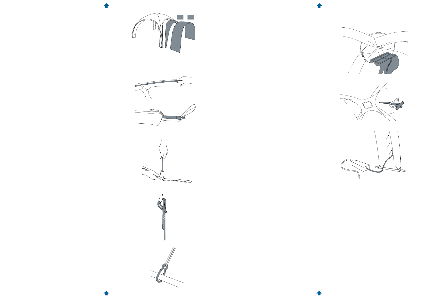
3.3.1. INFLATION WITH THE ELECTRIC PUMP
Screw the threaded end of the supplied hose onto the
discharge opening of the pump.
Plug the power cable into an electric socket. Note that
the Bravo 2000 has a booster that has to be activated
using the switch on the pump. Please also observe the
instructions and information supplied with the electric
pump.
3.3.2. INFLATION WITH THE HAND PUMP
The hand pump included in the contents of delivery is
equipped with various adapters that allow connection
to dierent valves. The hose should not be kinked or
compressed as this could result in leaks or breakage!
NOTE FOR INFLATING THE CANOPY: Two pump hoses are
always included with delivery. These can be connected so
that the canopy valves can be reached for inflation.
NOTE WHEN FILLING WITH COMPRESSED AIR:
XD 4: Assembley by only one person and corresponding
compressed air bottle in approx. 90 seconds. XD 5: Assem-
bley by only one person and with compressed air (compres-
sor - without lubricator and with pressure reducer or two
bottles) Alternatively an electric pump (Bravo 2000) can be
used. For longer operations, it is advisable to bring the tent
up to the recommended maximum operating pressure du-
ring the course of the operation. This usually requires only a
few strokes with the manual pump and can be done at any
time later. For the XD 5 - 300 mbar / for the XD 4 - 400.
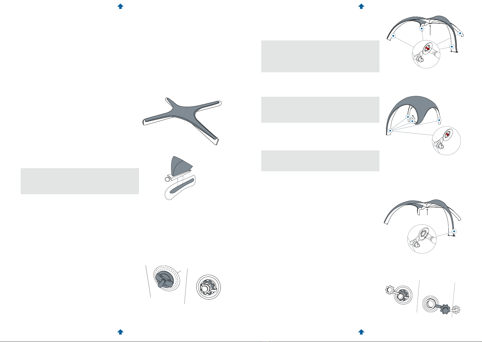
pressure in the tube has been reachedThe overpressure
valve prevents the tube from bursting if the air pressure
inside is too high, and because it is a safety-related
part, special attention should be given to it.
Before inflation, every overpressure valve should be
checked to ensure that it is functioning properly. To do
this, unscrew the valve housing from the socket and
check to make sure that the spring can be pressed in.
Make sure that the valve is properly screwed closed
again after testing.
Sand or dirt can jam the spring and valve, which may
prevent the valve from functioning correctly.
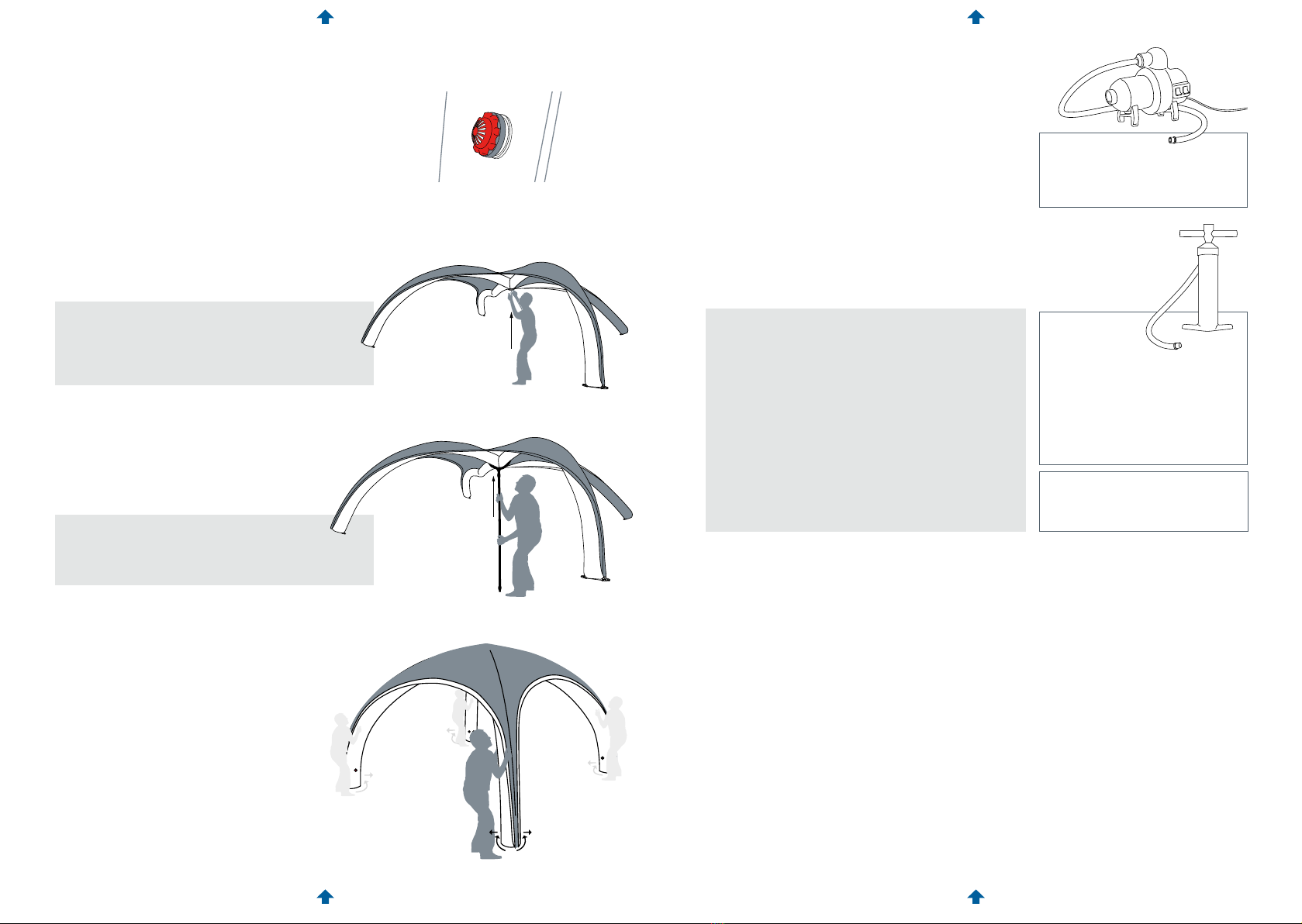
3.2.4 RAISING: XC 3 | XD 4/5/6/7
PLEASE NOTE: Raising the tent from the ground requires
some assistance. Before the tubes are fully inflated, the
middle of the tent — where the tubes intersect — must
be actively lifted o the floor. This prevents the tent from
possibly being damaged from being inflated invertedly.
When setting up the tent in sandy terrain, make sure
that no grains of sand get into the hoses or pumps
through valve openings, which could lead to damage
or leaks.
PLEASE NOTE: The specified maximum air pressure
must not be exceeded and is reached when the
overpressure valves open and the excess air beings to
escape.
For the tent to appear optically perfect, the tubes
should be aligned by hand after inflation and the roof
readjusted on the tubes if necessary.
TIP: Note the
valve plug
at the top of the pump body::
OPEN = pumps only on the
down stroke
(Single Action)
CLOSED = pumps on both the
up and down stroke
(Double Action)
See the notation
on the hose connection::
OUT = inflate
IN = deflate
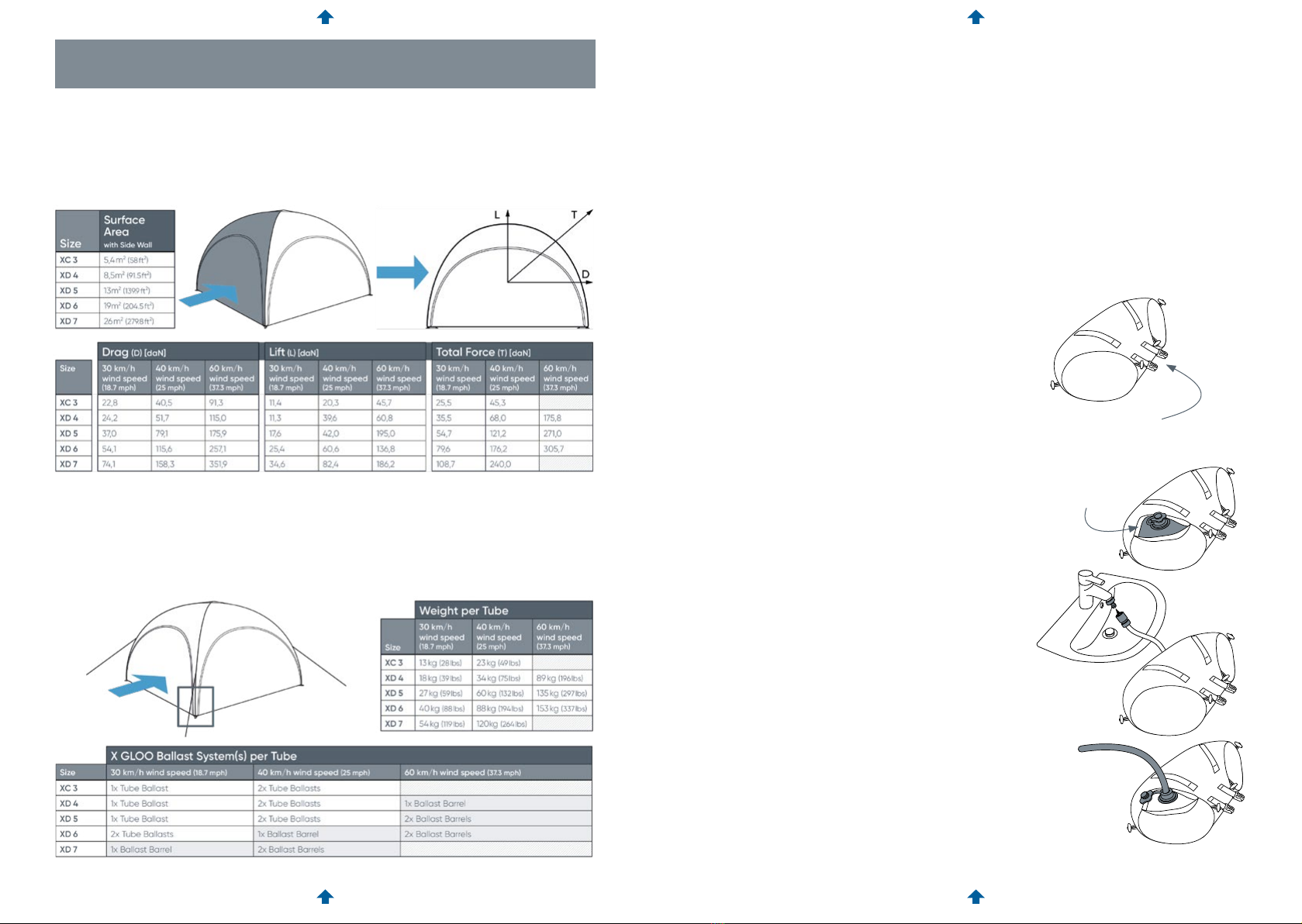
4. ANCHORING
The X GLOO XD and the XC series have been developed to be mobile and modular
lightweight tents. Despite their low weight, and the associated relatively low risk potential, the
following information must be read before use and diligently observed to prevent damage to
property and personal injury.
GENERAL INSTRUCTIONS
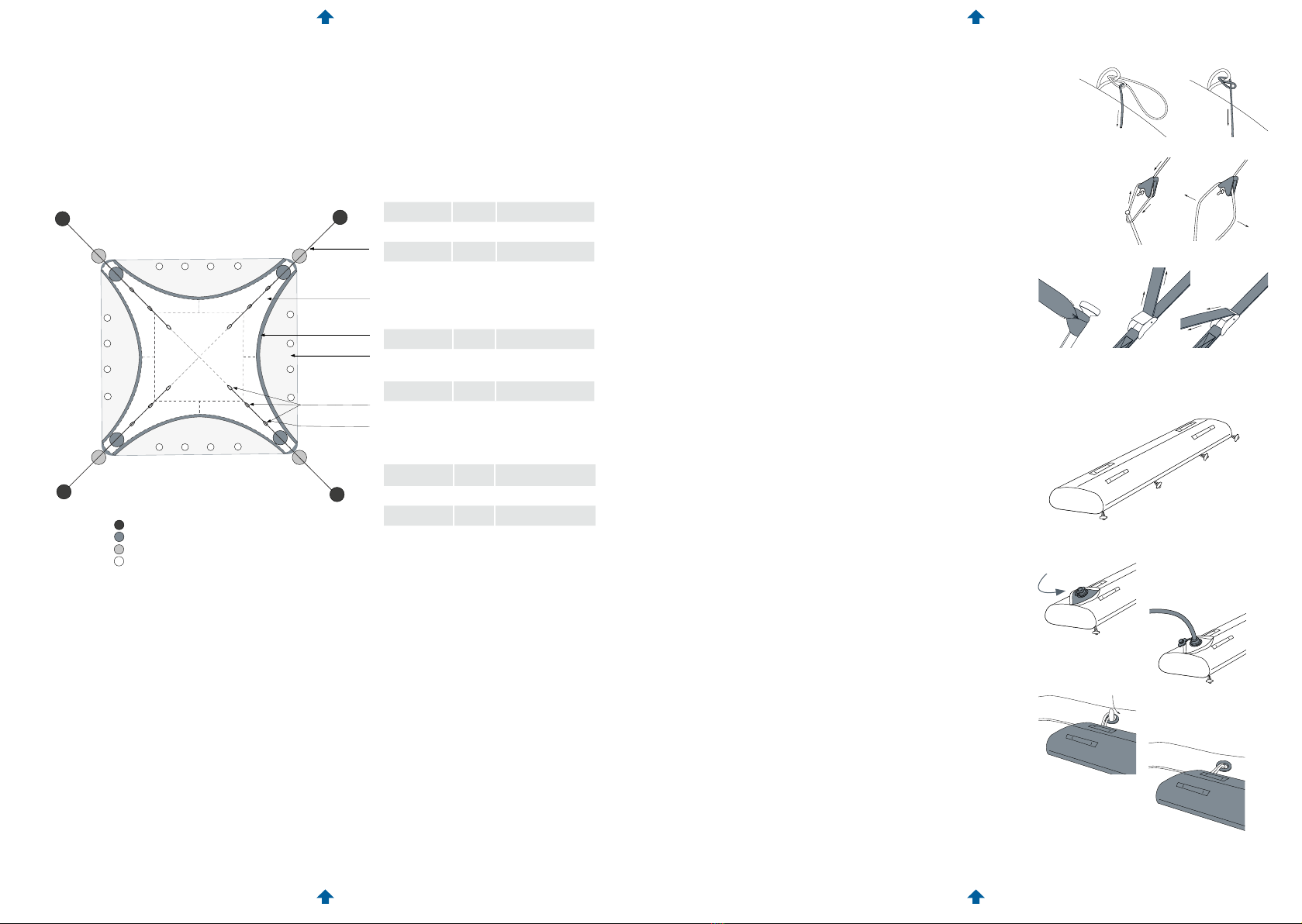
Depending on the nature of the terrain, the appropriate anchoring accessories must be used:
• On firm, packed soil, the X GLOO Anchoring Set (tent stakes) for the appropriate tent size
can be used.
• On snow or sand, the Snow Anchors or Sand Anchors are to be used in place of tent stakes,
respectively.
• On asphalt and similar hard surfaces, the tent must be weighted down using ballasts
sucient for the tent size and maximum expected wind speed.
The table in the wind speed certificate on the next page shows the type and quantity of
ballasts to be used, depending on the expected maximum wind speed and the tent size.
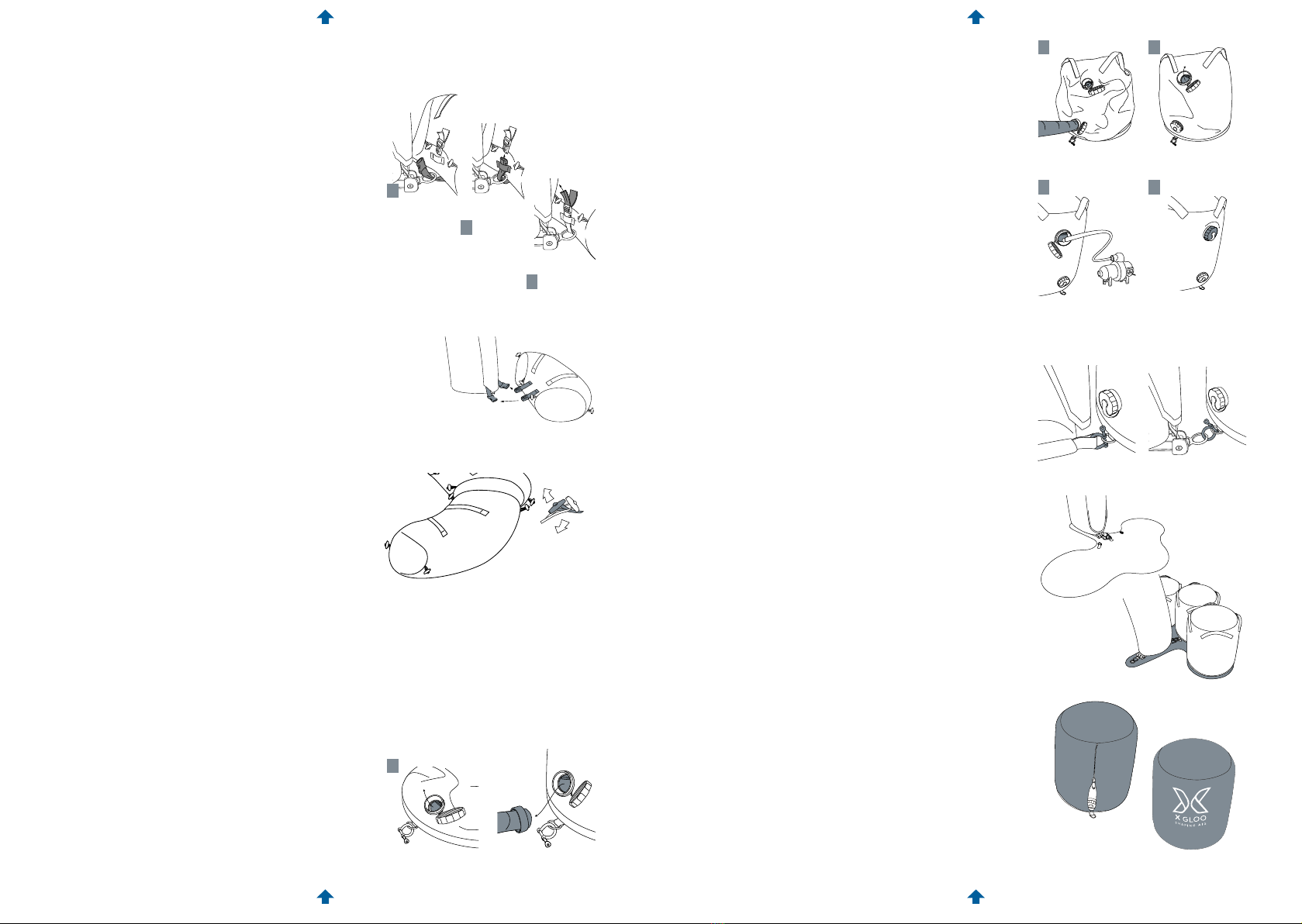
XD 4/5/6
XD 7
Observe this note when using the
compressed air cylinder in the X GLOO
tent series XD PROTECT.