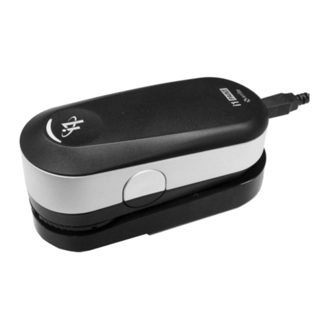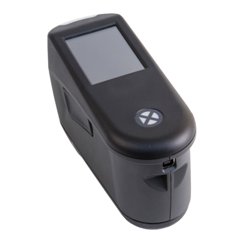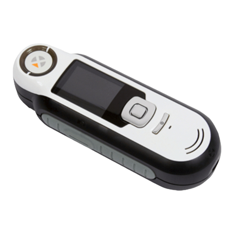
VERICOLOR®SPECTRO
4
Proprietary Notice
The information contained in this manual is derived from patent and proprietary data of
X-Rite, Incorporated. The contents of this manual are the property of X-Rite, Incorporated
and are copyrighted. Any reproduction in whole or part is strictly prohibited. Publication of
this information does not imply any rights to reproduce or use this manual for any purpose
other than installing, operating, or maintaining this instrument. No part of this manual may
be reproduced, transcribed, transmitted, stored in a retrieval system, or translated into any
language or computer language, in any form or by any means, electronic, magnetic,
mechanical, optical, manual, or otherwise, without the prior written permission of an officer
of X-Rite, Incorporated.
This product may be cover ed by one or more patents. Refer to the instrument for actual
patent numbers.
Copyright © 2007 by X-Rite, Incorporated “ALL RIGHTS RESERVED”
X-Rite and VeriColor are registered trademarks of X-Rite, Incorporated. All other logos, brand names, and product names mentioned
are the properties of their respective holders.
Warranty Information
X-Rite, Incorporated (“X-Rite”) warrants each instrument manufactured to be free of defects
in material and workmanship for a period of 12 months. This warranty shall be fulfilled by
the repair or replacement, at the option of X-Rite, of any part or parts, free of charge
including labor, F.O.B. its factory or authorized service center.
This warranty shall be voided by any repair, alteration, or modification, by persons other
than employees of X-Rite, or those expressly authorized by X-Rite to perform repairs, and by
any abuse, misuse, or neglect of the product, or by use not in accordance with X-Rite's
published instructions.
X-Rite reserves the right to make changes in design and /or improvements to its products
without any obligation to include these changes in any products previously manufactured.
Correction of defects by repair or replacement shall constitute fulfillment of all warranty
obligations on the part of X-Rite.
THIS WARRANTY IS EXPLICITLY IN LIEU OF ANY OTHER EXPRESSED OR IMPLIED
WARRANTIES, INCLUDING ANY IMPLIED WARRANTY OF MERCHANTABILITY OR FITNESS FOR
ANY PARTICULAR PURPOSE. THIS WARRANTY OBLIGATION IS LIMITED TO REPAIR OR
REPLACEMENT OF THE UNIT RETURNED TO X-RITE OR AN AUTHORIZED SERVICE CENTER
FOR THAT PURPOSE.
This agreement shall be interpreted in accordance with the laws of the State of Michigan and
jurisdiction and venue shall lie with the courts of Michigan as selected by X-Rite,
Incorporated.
