Xaoc Devices Poczdam 1989 Leibniz Device Komutator User manual

operator’s manual rev. 1989/X3/1.0
POCZDAM
the leibniZ binAry subsysteM
leibniz device
komutator
Model of 1989

sAlut
Thank you for purchasing this Xaoc Devices
product. Poczdam is a binary data routing
solution for the Xaoc Leibniz Subsystem. It
facilitates manual and remote switching
between two Leibniz data sources, modify-
ing individual bits of the data stream, and
re-clocking the data with its onboard volt-
age–controlled wideband oscillator or any
external clock signal. Poczdam is particularly
useful within complex Leibniz setups where
-
tween multiple modules. However, it can also
be employed in small creative patches, e.g., for
waveform splicing, disrupting rhythmic loops,
or generating digital chaos.
To better understand the device and avoid
common pitfalls, we strongly advise you to
read through the entire manual before use.
instAllAtiOn
The module requires 10hp worth of free space
in the Eurorack cabinet. Always turn the pow-
er off before plugging the module into the bus
board using the supplied 16-pin to 16-pin rib-
bon cable, paying close attention to power cable
pinout and orientation. The red stripe indicates
the negative rail and should match the dot or
–12V mark on the bus board as well as the unit.
Poczdam is internally secured against reversed
power connection; however, rotating the whole
16-pin header may cause serious damage
to other components of your system because it
will short circuit the +12V and +5V power lines.
Always pay close attention to the proper orien-
tation of your ribbon cable on both sides!
Besides power, you need to connect Poczdam
to other components of your Leibniz subsys-
tem. Poczdam comes with three ribbon data
cables with 10-pin plugs on both ends. Before
installing the data cables, we advise you to
read the entire manual and carefully plan
your Leibniz setup. Pay attention to the prop-
er orientation of the red stripe with pin #1
indicated by a dot or an arrow on each mod-
ule. Remember that proper data transmission
requires connecting inputs to outputs, just like
the analog signals in your modular system.
warning: make sure not to plug the eu-
rorack power into any data headers.
Doing so will destroy your Poczdam immedi-
ately and may jeopardize other Leibniz mod-
ules connected to it!
The module should be fastened by mounting
the supplied screws before powering up.
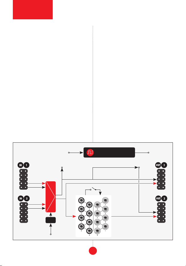
MODule OVerVieW
The main feature of Poczdam is switching be-
tween two data sources plugged into its two
Leibniz in ports at the back. Switching may
be done manually by pressing the illuminat-
ed button labeled source 1in the upper
trigger/gate signal plugged into the source
select input 2. The source data is selected
together with its associated clock and deliv-
ered to the Leibniz out1 header at the back.
Besides out1, the data from the selected
source is also available in the bank of eight
binary incoming data outputs jacks 3
on the front panel. Furthermore, apart from
2
module
explained

3
front panel
overview
4
9
1
2
5
6
11
7
10
8
3
the interface

the data bits, the clock of the selected source
is also available in the jack labeled incoming
clock out 4.
Next to the bit outputs is a bank of eight bit
outgoing data inputs 5. Signals connect-
ed there are converted to Leibniz data and
delivered to the out 2 header at the back.
All individual outgoing data inputs may
be optionally normalled to the signals from
corresponding incoming data outputs.
This normalization is activated with the link
button 6.
The data sent to the out 2 header is by de-
fault clocked with the same clock as out1;
however, you may replace the clock by plug-
ging a signal into the outgoing clock input
7on the front panel. One particularly suit-
able option is to use the onboard local clock
generator. Its frequency is controlled with a
rate knob 8, and a control voltage plugged
into the rate input 9. The clock operates in
three ranges switchable with a miniature slid-
er 10 : 800–15000Hz (middle position marked
Hz), 7kHz–120kHz (lower position marked
kHz), 0.1 MHz–2MHz (upper position marked
MHz), and is available at the out jack 11 .
the PrinCiPle Of OPerAtiOn
The block diagram of Poczdam is shown in
source selector (multiplexer) that switches
between two Leibniz data sources (togeth-
er with their associated clock) plugged into
the in1 and in2 headers. The selection is
toggled manually or via an external trigger/
gate signal. The selected data with its clock is
directly fed to the Leibniz out1 header at the
back. It is also delivered as 5V gate signals to
the bit output jacks on the front panel.
The signals from the front panel bit inputs are
fed to the Leibniz out2 header at the back.
The default state of each unpatched input is
low (0V). However, activating the link feature
creates a normalled connection: each input bit
receives a copy of the signal from the corre-
sponding bit out as its default state. It can still
be overridden by patching anything into it.
The clock for the out2 header may also be
replaced with anything plugged into the dedi-
cated outgoing clock in jack. Regardless of
the state of the link button, it is always nor-
malled to the clock of the selected data source.
The clock generator is a separate part of the
module. The frequency is controlled by CV and
a knob that acts as a manual offset. note: you
need to physically patch the clock out jack to
the outgoing clock in jack to use it as your
new clock alongside the outgoing data via the
Leibniz out2 header at the back.
PAtCh iDeAs
One obvious use of Poczdam is switching
data sources for Jena. Plug Drezno out to
in1 and Erfurt out to in2 in Poczdam. Plug
out1 from Poczdam to in of Jena, and out of
Jena back to Drezno. Doing so allows you to
conveniently switch between using Jena as a
waveshaper for audio and CV (coming from
Drezno) and a stable rhythm generator or a
complex LFO (with data from Erfurt).
4

block
diagram
5
Erfurt with Poczdam plugged into its input
allows one to select the source of the phase
increment. For example, plug Drezno to in1 of
Poczdam and Lipsk or Gera to in2. This setup
can easily go into crazy territory if you use
one of the bit outputs of Erfurt for switching
sources in Poczdam.
Use Poczdam to create a temporary loop.
For example, plug Erfurt into the Poczdam
in1 and the Poczdam out2 into the input of
Jena. Create a feedback loop from the output
of Jena into in2 in Poczdam. Doing so allows
you to easily switch between normal rhythm
playback and something complex and chaotic.
Experiment with the front panel jacks to make
even more feedback connections.
Both Ostankino II (with Moskwa II) and Er-
furt may act as sources of regular Leibniz
data sequences but with a radically different
character. They may be used for generating
interesting looped CV patterns when convert-
ed to analog with the DAC section of Drezno.
Quickly switching between these two is a
great way to introduce some variety to other-
wise repetitive results. Plug Ostankino's out-
put into Poczdam's in1 and Erfurt's output
into Poczdam's in2. Plug Poczdam's out1
into the input of Drezno. Plugging Poczdam's
out2 into Lipsk and then Lipsk back to Er-
furt facilitates switching on complex data se-
quences with a press of the link button.
ACCessOry
Our high quality Coal Mine black panels are
available for all Xaoc Devices modules. Sold
block diagram
Source select
Incoming clock output Outgoing clock input
Leibniz data
Leibniz clock
Leibniz data
Toggle
Clock outRate vc clock generator
Link

MAin
feAtures
Component of the
Leibniz Binary
Subsystem
Routing
Leibniz data
Reclocking
Leibniz data
Additional
CV clock generator
(up to 2MHz)
teChniCAl
DetAils
Eurorack synth
compatible
10hp, 30mm deep
Current draw:
+20mA/-10mA
Reverse power
protection
WArrAnty terMs
XAOC DEVICES WARRANTS THIS PRODUCT TO BE FREE OF DEFECTS IN MATERIALS OR WORKMANSHIP
AND TO CONFORM WITH THE SPECIFICATIONS AT THE TIME OF SHIPMENT FOR ONE YEAR FROM THE
DATE OF PURCHASE. DURING THAT PERIOD, ANY MALFUNCTIONING OR DAMAGED UNITS WILL BE
REPAIRED, SERVICED, AND CALIBRATED ON A RETURN-TO-FACTORY BASIS. THIS WARRANTY DOES NOT
COVER ANY PROBLEMS RESULTING FROM DAMAGES DURING SHIPPING, INCORRECT INSTALLATION OR
POWER SUPPLY, IMPROPER WORKING ENVIRONMENT, ABUSIVE TREATMENT, OR ANY OTHER OBVIOUS
USER-INFLICTED FAULT.
leGACy suPPOrt
IF SOMETHING GOES WRONG WITH A XAOC PRODUCT AFTER THE WARRANTY PERIOD IS OVER, NO
NEED TO WORRY, AS WE’RE STILL HAPPY TO HELP! THIS APPLIES TO ANY DEVICE, WHEREVER, AND
WHENEVER ORIGINALLY ACQUIRED. HOWEVER, IN SPECIFIC CASES, WE RESERVE THE RIGHT TO CHARGE
FOR LABOR, PARTS, AND TRANSIT EXPENSES WHERE APPLICABLE.
return POliCy
THE DEVICE INTENDED FOR REPAIR OR REPLACEMENT UNDER WARRANTY NEEDS TO BE SHIPPED IN
THE ORIGINAL PACKAGING ONLY AND MUST INCLUDE A COMPLETED RMA FORM. XAOC DEVICES CAN
NOT TAKE ANY RESPONSIBILITY FOR DAMAGES CAUSED DURING TRANSPORT. SO BEFORE SENDING
UNSOLICITED PARCEL WILL BE REJECTED AND RETURNED!
GenerAl inQuiries
FOR USER FEEDBACK SUGGESTIONS AND DISTRIBUTION TERMS, FEEL FREE TO CONTACT XAOC DEVICES AT
THE CURRENT PRODUCT LINE, USER MANUALS, FIRMWARE UPDATES, TUTORIALS, AND MERCHANDISE.
EASTERN BLOC TECHNOLOGIES MADE IN THE EUROPEAN UNION
ALL RIGHTS RESERVED. CONTENT COPYRIGHT © 2022 XAOC DEVICES. COPYING, DISTRIBUTION, OR
ANY COMMERCIAL USE IS STRICTLY PROHIBITED AND REQUIRES THE WRITTEN PERMISSION FROM XAOC
DEVICES. SPECIFICATIONS ARE SUBJECT TO CHANGE WITHOUT PRIOR NOTICE. EDITING BY BRYAN NOLL.
Table of contents
Other Xaoc Devices Recording Equipment manuals

Xaoc Devices
Xaoc Devices KAMIENIEC User manual

Xaoc Devices
Xaoc Devices OSTANKINO User manual

Xaoc Devices
Xaoc Devices PRAGA User manual

Xaoc Devices
Xaoc Devices ZADAR User manual

Xaoc Devices
Xaoc Devices DREZNO User manual

Xaoc Devices
Xaoc Devices Tirana User manual

Xaoc Devices
Xaoc Devices Moskwa II User manual

Xaoc Devices
Xaoc Devices KOSZALIN User manual

Xaoc Devices
Xaoc Devices SARAJEWO User manual