Contents
Chilli Dimmer 73-853-00 Issue 8 Page 2 of 30
Introduction........................................................................................................................... 3
This Manual ........................................................................................................................................................3
Conventions ........................................................................................................................................................3
Overview .............................................................................................................................................................4
Installation ............................................................................................................................ 5
Introduction .........................................................................................................................................................5
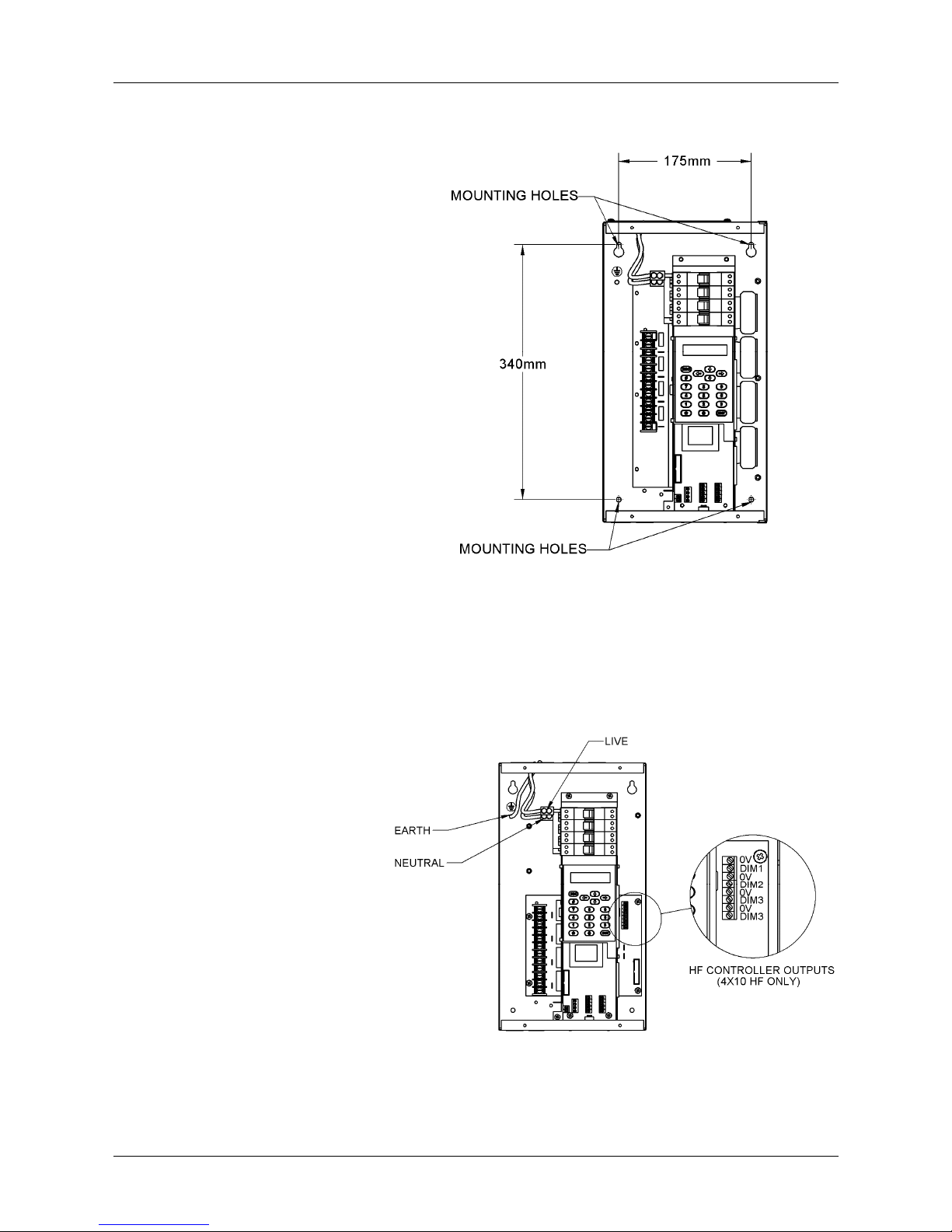
4 Channel Dimmers ............................................................................................................................................6
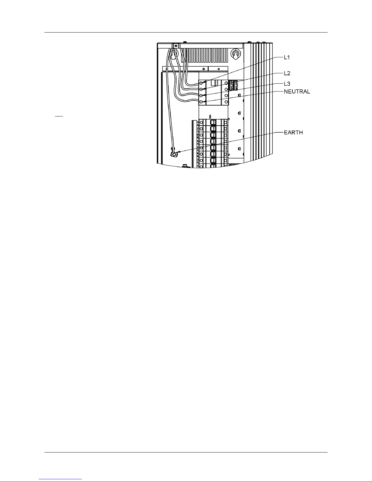
6 and 12 Channel Dimmers ................................................................................................................................8
12 Channel HF Dimmer ....................................................................................................................................10
24 Channel Dimmers ........................................................................................................................................12
DMX Connection...............................................................................................................................................14
Alarm Input Connection ....................................................................................................................................14
Chilli Network (Chilli Net) ..................................................................................................................................15
Network Terminals............................................................................................................................................15
Termination Resistors.......................................................................................................................................15
Network Connection..........................................................................................................................................16
User Interface ..................................................................................................................... 17
Introduction .......................................................................................................................................................17
Main Screen......................................................................................................................................................17
Menu Structure .................................................................................................................................................18
Manual Control..................................................................................................................................................18
Memories ..........................................................................................................................................................19
Sequences ........................................................................................................................................................22
Preheat .............................................................................................................................................................24
Dimmer Laws....................................................................................................................................................24
Topset ...............................................................................................................................................................25
Reset Dimmer...................................................................................................................................................25
DMX Controls....................................................................................................................................................25
Security .............................................................................................................................................................27
Chilli Net............................................................................................................................................................28
Area Control......................................................................................................................................................28
Alarm Input........................................................................................................................................................29
Technical Specification...................................................................................................... 30
Electrical ...........................................................................................................................................................30
Mechanical........................................................................................................................................................30
Environmental ...................................................................................................................................................30
EMC ..................................................................................................................................................................30
This equipment is designed for
professional lighting control only,
and is unsuitable for any other
purpose.
It should only be used by, or under
the supervision of, an appropriately
qualified or trained person.
Issue 8 - June 2009
Manual Stock No. 73 - 853 - 00
© Cooper Controls Ltd. 2009
Cooper Controls Ltd. reserves the
right to make changes to the
equipment described in this manual
without prior notice.
E & OE.
Cooper Controls Ltd.
Usk House
Llantarnam Park
Cwmbran
Gwent NP44 3HD
United Kingdom
Tel: +44 (0)1633 838088 *
Fax: +44 (0)1633 867880
e-mail: sales@zero88.com
Web: www.zero88.com
* 24 hour answerphone