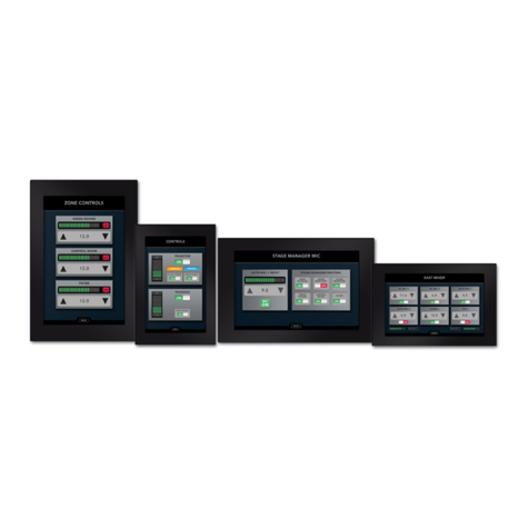
Xilica Audio Design NeuPanel Mini K1 User manual

1
NEUPANEL MINI
User Manual

2
Important Safety Information
1. READ THESE INSTRUCTIONS
All the safety and operating instructions should be read before the product is operated.
2. KEEP THESE INSTRUCTIONS
The safety and operating instructions should be retained for future reference.
3. HEED ALL WARNINGS
All warnings on the product and in the operating instructions should be adhered to.
4. FOLLOW ALL INSTRUCTIONS
All operating and use of instructions should be followed.
5. DO NOT USE THIS APPARATUS IN WATER.
Do not use the product near water. For example, near a bathtub, wash bowl, kitchen sink, or laundry tub, in a wet basement, or near a swimming pool, and the
like.
6. CLEAN ONLY WITH DRY CLOTH.
Unplug the unit from the wall outlet before cleaning.
7. DO NOT BLOCK ANY VENTILATION OPENINGS
Slots and openings in the cabinet back or bottom are provided for ventilation, to ensure reliable operation of the limit and to protect it from overheating.
These openings must not be blocked or covered. The openings should never be blocked by placing the product on a bed, sofa, rug, or similar surface.
This product should never be placed near or over a radiator or heat source. This product should not be placed in a built-in installation such as a
bookcase or rack unless proper ventilation is provided or the manufacturer’s instructions have been adhered to.
8. DO NOT INSTALL NEAR ANY HEAT SOURCES
This product should be situated away from heat sources such as radiators, stoves or other products (including amplifiers) that produces heat.
9. DO NOT DEFEAT THE SAFETY PURPOSE OF THE POLARIZED OR GROUNDING-TYPE PLUG
A polarized plug has two blades with one wider than the other. A grounding-type plug has two blades and a third grounding prong. The wide blade or the
third prongs are provided for your safety. If the provided plug does not fit into your outlet, consult an electrician for replacement of the obsolete outlet.
10. PROTECT THE POWER CORD FROM BEING WALKED ON OR PINCHED PARTICULARLY AT PLUGS, CONVENIENCE RECEPTACLES, AND THE
POINT WHERE THEY EXIT FROM THE APPARATUS.
11. ONLY USE ATTACHMENTS/ACCESSORIES SPECIFIED BY THE MANUFACTURER.
12. USE ONLY WITH CART, STAND, TRIPOD, BRACKET, OR TABLE SPECIFIED BY THE MANUFACTURER, OR SOLD WITH THE APPARATUS. WHEN A
CART IS USED, USE WITH CAUTION WHEN MOVING THE CART/APPARATUS TO AVOID INJURY FROM TIP-OVER.
Do not place this unit on an unstable cart, stand, tripod, bracket, or table. The unit may fall, causing serious injury to someone, and serious damage to
the appliance. A unit and cart combination should be moved with care. Quick stops, excessive force, and uneven surfaces may cause the product and
cart combination to overturn.
13. UNPLUG THIS APPARATUS DURING LIGHTNING STORMS OR WHEN UNUSED FOR LONG PERIODS OF TIME.
For added protection for this unit during a lightning storm, or when it is left unattended and unused for long periods of time, unplug it from the wall
outlet and disconnect the antenna or cable system. This will prevent damage to the unit due to lightning and power surges.
14. REFER ALL SERVICING TO QUALIFIED PERSONNEL. SERVICING IS REQUIRED WHEN THE APPARATUS HAS BEEN DAMAGED IN ANY WAY. SUCH
AS, WHEN THE POWER SUPPLY CORD OR PLUG IS DAMAGED, LIQUID HAS BEEN SPILLED, OR OBJECTS HAVE FALLEN INTO THE APPARATUS, THE
APPARATUS HAS BEEN EXPOSED TO RAIN OR MOISTURE, DOES NOT OPERATE NORMALLY, OR HAS BEEN DROPPED.
15. WARNING: TO REDUCE THE RISK OF FIRE OR ELECTRIC SHOCK, DO NOT EXPOSE THIS APPARATUS TO RAIN OR MOISTURE.
16. APPARATUS SHALL NOT BE EXPOSED TO DRIPPING OR SPLASHING AND NO OBJECTS FILLED WITH LIQUIDS, SUCH AS VASES, SHALL BE
PLACED ON THE APPARATUS.

3
Table of Contents
What’s in the box 4
NeuPanel Mini series models 5
Hardware descriptions and functions 6-7
Hardware device connection
a. To network 8
b. To mains power 9
Install Xilica Designer software
a. Windows installation 10
b. Mac installation 11
Xilica Designer’s Network View
a. Device network status 12
b. Connection troubleshoot 13-14
c. Manual assignment of IP addresses 15-17
d. Firmware upgrade 18
Xilica Designer’s Project view
a. Create a new project 21
b. Map device(s)/Online mode 27

4
What’s in the Box
• NeuPanelserieswallcontroldevice
• Mountingscrews(colorspecictowallcontrolcolor)
• Surfacemountbackbox(NeuPanelminidevicescanbeushorsurfacemounted)
• Externalpowersupply
What you need to Provide
• Mac or PC computer with a processor 1GHz or higher
• Windows7orhigher
• MacOSX
• 500MBoffreespace
• 1GBgraphicscard
• 4GBofRAM
• ExternalpowersupplyisincludedbutitisrecommendedtouseaPoErouter/switch
• Ethernetcable(Cat5/6)
Getting Help
Additional Help Files and video tutorials are available at our website: www.xilica.com
For further technical support, please email: [email protected] and we’ll connect you with a solutions
engineer. Alternatively, you can call our worldwide offices for immediate assistance:
NorthAmerica&RestofWorld:+1905-770-0055
Europe: +3129940-1100
China&HongKongSAR: +8522604-9382
NeuPanel: Getting started

5
The Xilica NeuPanel Mini wall controls come in five different configurations.
Please note that the NeuPanel series is not compatible with Solaro series DSP.
NeuPanel Mini K1
Control any single value change, including: gains, threshold, frequency, etc.
NeuPanelMiniK4
Control any four-value changes, including: gains, threshold, frequency, etc.
NeuPanelMiniS4
Control any four buttons in the system design including Preset selection.
NeuPanelMiniS8
Control any eight buttons in the system design including Preset selection.
NeuPanelMiniS4K1
Control any four buttons in the system design including Preset selection and
control of any single value change, including: gains, threshold, frequency, etc.
NeuPanel:Model variants

6
Power status LED When the device is Powered On, this indicator will light blue.
Network LED WhenthedevicehasanEthernetcableconnected,theNetworkstatus
LEDwilllightorangeoncetheprocessorinitializes.IfthereisnoEthernet
cable attached, this light will remain off.
Note:WhentheNetworkstatusLEDison,itdoesnotindicatethatyou
haveestablishedaNetworkconnection-onlythatanEthernetcableis
connected to the processor. Proper Network connection is displayed in
Xilica Designer’s Network view. For more detail please refer to ‘Network
view’onPage12.
On/off push button Program processor on/off control functions into any Mini devices on/off
push button using the Xilica Designer software.
Label slot Place supplied or unique label in label slot and cover with included
protective plastic cover.
Level control Program processor level control function into anyy Mini devices using the
Xilica Designer software.
Level indicator LED
NeuPanel:Hardware device

7
Ethernet connector ConnecttothenetworkusinganEthernetCat5/6cable(andpowerif
usingPoweroverEthernet(PoE).TheportisastandardRJ45(Ethernet).
Power supply connector Power the device using the included external power supply. If you are
sendingPoweroverEthernet(PoE),theexternalpowersupplyisnot
needed.
IP Reset button ResettheIPAddressbyfollowingtheIPResetProcedure.(Referto
connectiontroubleshooting:Page13)
USB connector Not used. (Xilica use only)
NeuPanel:Hardware device

8
Initial Device Connectivity:
Xilica processors and control devices run on a network based infrastructure and are set up and controlled by
ahostcomputerviaEthernetusingtheXilicaDesignersoftware.
A network connection can be made between the computer and processor using:
a)DHCPenabledRouterorServer/Routercombination(Recommended)
b)oranon-DHCPenablednetworkconnection(i.e.PoEswitches).
Note:DHCPenabledRouter/switchgearshouldbeturnedonrst,withallEthernetcablesconnectedtothe
hardware prior to powering on the Hardware. This will allow for proper handling of IP address distribution to
the Hardware. The IP address assignment is automatic if connected to a DHCP enabled network.
A) DHCP enabled router or server/router combination (Recommended)
POWER MAINS: 90-240 VAC 50-60Hz, 20VA
FUSE: T2.5A-250V
I
O
Ethernet
Control
Designed and Engineered in Canada
IP Reset G - + G - + G - + G - + G - + G - + G - + G - + G - + G - + G - + G - + G - + G - + G - + G - +
INPUTS OUTPUTS
USE ONLY WITH 250V FUSE
Power over Ethernet
POWER MAINS: 90-240 VAC 50-60Hz, 20VA
FUSE: T2.5A-250V
I
O
Ethernet
Control
Designed and Engineered in Canada
IP Reset G - + G - + G - + G - + G - + G - + G - + G - + G - + G - + G - + G - + G - + G - + G - + G - +
INPUTS OUTPUTS
USE ONLY WITH 250V FUSE
Wall Controls
PC or Mac
PC or Mac
B) Non-DHCP direct connection
NeuPanel:Device connection

9
AllwiredconnectionsuseastandardRJ45Cat5/6(Ethernet)connection.
Xilica Designer and XTouch Applications can also be connected via a Wi-Fi connection, but this is not
recommended.
StandardRJ45cable
A) DHCP enabled router or server/router combination (Recommended)
With DHCP enabled routers and servers, the mini wall control will automatically obtain the IP address upon
power up and connection.
ItisrecommendedtousearouterandPoEswitch.ThiscomboprovidesDHCPaswellaspowertothewall
controls. Linksys routers and Netgear switches are recommended.
B) Non-DHCP indirect connection (Non-DHCP Poe switches)
When Mini wall controllers are connected indirectly to the computer network via a switch and DHCP is not
available to assign IP addresses, the connection process is not automatic.
1. Single mini device (Non-DHCP)
Once no DHCP is detected, the mini controrl will either try to connect using the IP address last
assignedandstoredonthedeviceorattempttoreverttoitsdefaultIPaddressof169.254.64.64.
Under some conditions, the processor may refuse to relinquish its stored IP addresses or revert to its
defaultIPaddressandthusrefusetoconnect.WerecommendperforminganIPReset(Page13).
2. Multiple mini controls (Non-DHCP)
For multiple mini controls connected to the network with no DHCP available, the user will have to
manuallyassignuniqueIPaddressestoeachdevice.(Page15-17)
Connect Mains Power
Beforegettingstarted,pleasecheckthattheXilicaDesignersoftwareanddevicermwarearecompatible/up
todate.(PleaserefertoFirmwareupgradeonPage18)
Power On Devices
Withyourdevicesconnectedasanetwork,poweronalldevices.Onpowerup,thebluepowerstatusLED
will light.
IfthedevicehasanEthernetcableconnected,theorangeNetworkLEDwilllightoncethedeviceinitializes.
(PleasenotethatthisdoesnotmeanyouhaveestablishedanetworkconnectionbutonlythatanEthernet
cable is connected. Network connection is displayed in Xilica Designer’s Network view.
Upon power up, the processor will search for a DHCP router, switch or server to obtain an IP address.
If it locates a DHCP server or router, it will connect quickly. If not, the device will revert to its default IP
address(169.254.64.64). If you are using a non-DHCP direct connection, please follow ‘Manual IP address
assignment’onpage15-17.
NeuPanel:Device connection

10
Xilica Designer Software Installation
Windows Platform Installation
1. WiththeXilicaUSBthumbdriveincludedwithyourXilicaproduct,transferthelesfromtheUSBtoa
memorable location on your computer. Alternatively, you can download the latest version of the
Xilica Designer software from the Xilica website (www.xilica.com). It is highly recommended that you
make sure you are using the latest version.
2. Doubleclickonthe‘XilicaDesigner.exe.’lesavedonyourcomputer.
3. Whenaskedtoinstallthele,click‘Install’tocontinue.
4. Allowtheprogramtocompletetheinstallationprocess.Thismaytakeaseveralminutes.
5. Whencomplete,Windowswillaskforpermissiontoallowrewallaccess.Thesuggestedsettingisto
allow Xilica Designer to communicate in Private networks, such as home or work. Allow access to
public networks at your own discretion. Check the appropriate boxes, then click ‘Allow Access’ to
finish.
6. TheXilicaDesignersoftwareisnowinstalled.
Installation Notes
If a personal Firewall is set up on your computer,
a pop-up Firewall window may ask whether users
wantto“Block”or“Allow”XilicaDesignerfrom
accessingthenetwork.Select“Allow”tocontinuethe
installation.
NeuPanel: Xilica Designer installation

11
Mac OSX Platform Installation
1. WiththeXilicaUSBthumbdriveincludedwithyourXilicaproduct,transferthelesfromtheUSBtoa
memorable location on your computer. Alternatively, you can download the latest version of the
Xilica Designer software from the Xilica website (www.xilica.com)
2. Doubleclickonthe‘XilicaDesigner.mpkg.’lesavedonyourcomputer.
3. OSXwilldisplayaninstallationdialogue.Readandfolloweachstepcarefully,thenclick‘continue’to
proceed.
4. Whentheinstallationissuccessful,thefollowingdialoguewillbedisplayed.
NeuPanel: Xilica Designer installation

12
Launch the Xilica Designer Software
Upon launching the Xilica Designer software, a start-up window will pop up.
You may select a ‘New Design Project’, ‘Open Design Project’, ‘Start Network View’ or ‘Start Dante View’.
(Network and Dante View are also available within the Xilica Designer software).
Select ‘Start Network View’.
Network view
The Network View displays all processors and control devices on the network. The Network View displays
information such as the device model, a network connection indicator, Computer address, IP address,
Manufacturer and the firmware version.
In Network View, you should see your device(s) listed.
At the top left of the device block is a network connection indicator. This indicator displays three colors: red,
yellowandgreen.(CircledinRed)
Network Connection Indicators:
Green: The device is Connected and operational.
Yellow: The device is Connected and online, but not operational. Hovering over the network indicator
will display a pop-up message of identified problems. (Normally this would indicate that no
device design is loaded.)
Red: Thedeviceisnotconnectedandofine.ThereisnocommunicationbetweentheXilica
Designer software and the device. Please check all cables, modular cards, connections and
power. If the processor is busy performing a firmware upgrade or is in the process of
rebooting,thismaybeatemporaryofineinterruption.
At times you may just see an exclamation mark (!). This indicates that a firmware upgrade is available.
Normally this is not an issue unless there are updated modules in the project file that the outdated firmware
does not support.
NeuPanel:Network view

13
Connection Problems?
Yellow Network indicator
In Xilica Designer’s Network View, if there is a Yellow network connection indicator at the top left of the
device, the device is connected and online, but Not operational. To assist in identifying the problem, hover
your cursor over the device network indicator and a pop-up message will identify the problems it has
detected.
Probable causes include:
Non-DHCP Connection
When you are Not connected to a DHCP enabled router/switch/server, the device will revert to its auto-
conguredIPAddress(169.254.64.64).InNetworkView,youcanviewtheIPaddressdisplayedforyour
device(s). If the default IP address is shown, the default IP address is in effect.
IfthedefaultIPaddressisincorrect,pleasefollowthe‘IPReset’instructionsbelow.
For multiple devices connected to the network with no DHCP available, the user will have to manually assign
unique IP addresses to each device. Please refer to ‘Manual IP address assignment’ and ‘Assigning a Static IP
Addresstoyourcomputer’onPage15-17.
DHCP Connection
If you are connected to a DHCP enabled router/switch,
1. Reboottherouter/switch.
2. Restartthedevice.
3. ShutdowntheXilicaDesignersoftwareandrestarttheprogramagain.
4. Thenetworkconnectionindicatorshouldnowbegreen,indicatingthattheprocessorisconnected,
online and operational.
Note: If you are Not connecting via Wi-Fi, turn off your device’s Wi-Fi so the device can connect to the
desired network.
If the connection indicator is still Yellow (connected but Not operational) after the reboot procedure, it is
possible that the device is holding onto a previously assigned IP address and is not allowing the processor to
revert to its default IP address. To resolve this issue, the processors’ network settings and password need to
bereset.PleasefollowtheIPreset/Resetprocessornetworksettingsandpasswordprocedure.
IP Reset / Reset Device Network Settings
1. Shut down the Xilica Designer software.
2. PowerOffthedevice.
3. Atthebackofthedevice,youwillseeasmall,recessedpushbuttonlabelled“IPReset”.
4. PushtheIPResetbuttoninward.
5. Whileholdingthebuttonpushedin,powerupthedevice.
6. Wait5-10secondsafterpowerupuntiltheorange“Network”lightbeginstoash,andthenrelease
theIPResetpushbutton.
7. Waitforthedevicetopowerupcompletely.Thismaytakeuptoseveralminutes.
8. OpentheXilicaDesignersoftwareandselect“StartNetworkView”
9. InNetworkView,thenetworkstatusindicatorshouldnowbegreen(Connectedandoperational)
IfthedefaultIPaddressof169.254.64.64isnotshown,you’reeitherusinganincorrectlycongured
Static IP setup, or the DHCP server still isn’t available to the device.
NeuPanel: Connection troubleshoot

14
Software network problems continued
Device Not Ready
If the pop-up message shown says Device Not ready, please wait a few minutes until the device is ready. The
device should then connect and the indicator turn Green.
Device Schematic Not Ready
The device has already been loaded with a DSP design.
1. Please wait a few minutes to allow the connection to process. If it does not connect, restart the
Xilica Designer software and reboot the device.
Error in Firmware Upgrade
Thepopupmessageshownwillprintoutanerrorcode.RetrytheFirmwareUpgradeagain.
Device can communicate to Xilica Designer with UDP but cannot communicate with TCP
1. RightclickthedeviceinNetworkviewandselect“Device Set up”.Selectthe“Network tab”
2. Click“TCP Test” / “UDP Test”to test TCP / UDP connections.
3. Iffailed,pleasecheckyourPC’srewallorroutersettings.IfyouarenotconnectingviaWi-Fi.make
sure that Wi-Fi is turned off.
4. Click“Start Network Statistics”to see network statistic information.
5. Onceachangehasbeenmade,restartXilicaDesignerandreviewyourdeviceconnection.
NeuPanel: Connection troubleshoot

15
3. Whennished,select“Apply”tosavechangesandthen“Done”toexit.
4. Repeatsteps1through3foreachsubsequentprocessorsoeachprocessorhasitsownuniqueIP
address.(Forexample:192.168.1.180/181/182...)
ThedeviceswillappearOfineinNetworkviewuntilyouareabletoassignastaticIPaddresstoyour
computer.(Page15)
2. Inthe‘Network’ tab, select “Change Network Configuration”todisableDHCPandtoinsertIP
addresses manually (It also provides two built-in test procedures, device security, and device
information along with Dante Configuration, if applicable).
Manual Assignment of IP Addresses for devices
There are applications that require the IP address to be manually assigned (the same solution may apply to
some connection issues).
To manually assign IP addresses,
1. In the Network View, right click the device and select ‘Device Setup’.
NeuPanel: Manual IP Address

16
Assigning a Static IP address for your computer
The following process applies to manually assigning a unique static IP address to your computer.
Windows platform
1. In the start menu, select control panel.
2. Click‘Network and Internet’. Under the heading ‘Network and sharing center’, select ‘View
network status and tasks’
3. Clickon‘Change adapter settings’ on the left tab.
4. Select‘Local Area Connection’ and click on the Properties button. Select Internet Protocol Version 4
(TCP/IPv4) then ‘Properties’ to access the manual IP settings.
5. Setupyourcomputer’sIPaddresstobe192.168.1.XwhereXcanbeanyvaluefrom0-255,but
unique from other manually assigned device IP addresses.
6. UsethefollowingsettingsforyourPC’suniquestaticaddress:
IP address: 192.168.1.X (X is any value from 0-255 but unique from other device IP addresses)
Subnet mask: 255.255.255.0
Gateway: 192.168.1.1
DNS Servers: 192.168.1.1
7. Ifyourdevicesaresetupfollowingthe‘ManualDeviceIPAssignment’and‘AssigningaStaticIP
Address to your computer’ sections, the devices will now appear online and connected in Xilica
Designer’s Network view.
NeuPanel: Manual IP Address

17
Mac platform
1. From the Apple menu, select System preferences.
2. Select‘Network’. From the sidebar, select the network interface you are using.
3. Thenclick‘Advanced...’
5. EnterastaticIPaddressintheIPv4Addresseld.Setupyourcomputer’sIPaddresstobe
192.168.1.XwhereXcanbeanyvaluefrom0-255,butuniquefromotherdeviceIPaddresses.
6. Usethefollowingsettingsforyourcomputersstaticaddress:
IP address: 192.168.1.X (X is any value from 0-255 but unique from other device IP addresses)
Subnet mask: 255.255.255.0
Router: 192.168.1.1
7. Click‘Ok’ and ‘Apply’ to apply your changes. Then reboot the Xilica Designer software.
If your devices are set up following the ‘Manual Device IP Assignment’ and ‘Assigning a Static IP Address to
your computer’ sections, the devices will now appear online and connected in Xilica Designer’s Network
view.
4. IntheTCP/IPtab,setConfigure IPv4 to ‘Manually’ using the drop down menu.
NeuPanel: Manual IP Address

18
Firmware Upgrade
It is strongly recommended that you check the Xilica website (www.xilica.com) frequently for the latest
software and firmware versions, as these updates may contain critical bug fixes and new features.
Note: Using an older version of software with a newer firmware or newer software with an older firmware will
work but some of the features may not be available and bugs could exist.
Beforeyoubegin,checkyoursoftwareandrmwareversions.
1. In Xilica Designer’s Network View, select ‘Start Network View’.
The Network View shows all processors and devices connected to the network.
Thedevice’scurrentrmwareversionisdisplayedhere.(Ex.Version1.0.0)
2. Toviewthecurrentsoftwareversion,clickonthe“About”tabatthetopofthesoftware.Thiswindow
will display your current software version.
Matching the Firmware
To assist you in determining which firmware file is appropriate for your device, refer to the chart below.
Note: The file structure may be different from the date that this list was created. Always check the Xilica
website (www.xilica.com) to keep updated.
#_#_#Representsthe3digitversioncodeofthermwareupdate.
(SOLARO_#_#_#.img) Solaroseries:QR,FR
(NEUTRINO_#_#_#.img) Neutrinoseries:A,A-D(AES),A-N(Dante),A-ND(Dante,AES)
(UNO_#_#_#.img) Unoseries:U,U-D(AES),U-N(Dante),U-ND(Dante,AES)
(NEUTRINO-AEC_#_#_#.img)NeutrinoAECSeries
(UNO-AEC_#_#_#.img) UnoAECSeries
(RIO_#_#_#.img) RioSeries
(NEUPANELMINI_#_#_#.img)NeuPanelMiniSeries:K1,K4,S4,S8,S4K1
(NeuPanel Touch_#_#_#.zip) NeuPanel Touch Device
NeuPanel: Firmware upgrade

19
Step-by-Step Firmware Upgrade Guide
The hardware device must be connected and operational (Green indicator) before upgrading the firmware.
1. Download the latest firmware version for your device from our website. (www.xilica.com)
In Network View, all the units on the network are displayed. The network connection indicator is displayed at
the top left of each device.
2. Saveanydesignlesfromthedeviceontoyourcomputer.Allprogrammeddataonthedevicewill
be erased during the upgrade process. (To save, navigate to the File tab at the top left of the software
and click ‘Save’.)
After the firmware upgrade is complete, you may reload saved design files back into the device.
3. Rightclickthedevicethatyouwouldliketoupdate.Select‘FirmwareUpgrade’.
4. Apopupwindowwillaskyouifyou’dliketoproceedwiththermwareupgrade.Select“OK”to
proceed.
NeuPanel: Firmware upgrade

20
6. AstatusbarinthedevicewindowwillmonitortheFirmwareupgradeprogress.
7. WhentheFirmwarehasbeenuploadedtothedevice,thedevicewillautomaticallyrestartand
update its internal data. This may take several minutes.
8. Duringthisperiod,thedevicenetworkindicatorwillturnREDandappearofine.
DONOTPOWEROFFTHEDEVICEasthedeviceisperformingself-initialization.
9. Oncethedeviceisinitialized,thestatusindicatorwillbecomeYellow.Thisindicatesthatthedevice
does not have a design file loaded to it yet.
NOTE: Powering Off your device during a firmware upgrade can result in a complete corruption
of the processor. If this happens, please follow the ‘Xilica Designer: Firmware Upgrade’ guide.
Note: If more than one unit needs a firmware upgrade, you can save time by updating them all at the same
time. This can be done as long as they are the same Network and have a green network indicator (connected
and operational), as displayed on the Network View page.
10. Thenetworkindicatorofthedeviceshouldnowbegreenandthedeviceisreadyforuse.
5. Click’Ok’toselectalefromyourcomputer.Thennavigatetotheappropriatermwarelethatyou
havedownloadedfromourwebsite.Selectthecorrectleandclick“Open”.
(Ex.ANeutrinoA1616-Nisbeingupdated,sothermwareleatthetimeofthisQSGisNeutrino_5_4_2.img.)
NeuPanel: Firmware upgrade
This manual suits for next models
4
Table of contents
Other Xilica Audio Design Control Unit manuals
Popular Control Unit manuals by other brands

Velleman
Velleman VMA424 user manual

Madas
Madas M16/RM N.C. DN 65 EEX manual

Profort
Profort multiGuard DIN6 quick guide

DEEP SEA ELECTRONICS
DEEP SEA ELECTRONICS DSE8910 installation instructions

STATUS SCIENTIFIC CONTROLS
STATUS SCIENTIFIC CONTROLS LC Series Installation and Hardware Configuration Manual

Exhausto
Exhausto EBC 10-P Installation & operating manual